Straumann Novaloc Manual

Technical Information
Straumann® Novaloc® Retentive System for Hybrid Dentures
Basic Information
490.115.indd 1 24/06/2019 14:02

Contents
. The Novaloc® Retentive System for hybrid dentures
1.1 Straumann® Novaloc® Retentive System at a glance 1
. Creating a new overdenture with the Novaloc® Retentive System
2.1 Procedure in the dental office 2
2.2 Procedure in the dental lab 3
2.3 Procedure in the dental office 5
. Using the Novaloc® Tools
3.1 Novaloc® Matrix Housing Extractor 6
3.2 Novaloc® Demounting Tool for Mounting Inserts and Model Analog Reposition Aid 6
3.3 Novaloc® Mounting and Demounting Tool for RetentionInserts 7
. Special featured Novaloc® Components
. Product reference list
. Appendix
6.1 Appendix A 15
6.2 Appendix B 17
490.115.indd 2 24/06/2019 14:02

1
. The Novaloc® Retentive System for
hybrid dentures
The Straumann® Novaloc® Retentive System for hybrid dentures offers an innovative car-
bon-based abutment coating (ADLC¹) with an excellent wear resistance, overcoming up to 60°
implant divergence. Both the straight and 15° angled abutments are available in various abut-
ment heights, covering a broad range of clinical implant situations. Together with its durable
PEEK²matrices, the Novaloc® Retentive System provides a unique and long-lasting attachment
performance.
. Straumann® Novaloc® Retentive System at a glance
Novaloc® Abutment, straight Novaloc® Abutment, 15° angled°
+/- 20° +/- 20°
11
23 4
5
6
77
¹Amorphous Diamond-Like Carbon
²Polyether ether ketone
³ 1.5 to 6.5 mm for BLX 1 to 6 mm for all other systems
⁴ 6 lengths: 2.5 to 7.5 mm for BLX 2 to 6 mm for all other systems
‒ PEEK²matrix inserts offering excellent chemical
and physical properties
‒ Matrix accommodates up to 40° prosthetic diver-
gence between two abutments
‒
6 retention strengths offer optimal adjustment of
the denture retention
‒
Matrix Housing available in titanium, or color-neu-
tral PEEK² for a more aesthetic outcome
‒ Carbon-based abutment coating (ADLC¹) offering
a smooth surface and ultimate hardness
→ for lasting wear resistance
‒ Compatible to the standard SCS Screw-driver
→ self-retaining system preventing aspiration
→ Small stud hole prevents food accumulation
‒ Compatible to the standard SCS Screwdriver
→ self-retaining system preventing aspiration
‒ 6 abutment heights for Novaloc® straight abut-
ment³
‒
5 abutment heights for Novaloc® angled abut-
ment⁴
‒
Laser-marked abutment height and implant
platform
‒ Rely on the original implant-abutment connection
→ Perfectly matching components
→ Excellent service and support
1
2
3
4
5
6
7
2
490.115.indd 1 24/06/2019 14:02

2
. Creating a new overdenture with the
Novaloc® Retentive System
Step 1 – Selecting the abutment
Ensure that the implant shoulder is not covered by
hard or soft tissue
Determine the appropriate abutment height by
counting the marks on the Novaloc® Plan Abut-
ments*.
Step 2 – Inserting the Abutment
Screw the Novaloc® Abutment tightly by hand into
the implant using the Straumann® Screwdriver.
Torque the abutment to 35Ncm using the Ratchet,
the Torque Control Device and the SCS Screwdriver.
Step 3 – Sealing the screw channel of the Novaloc®
Angled Abutment
Use Teflon and composite in order to seal the screw
channel of the Novaloc® Angled Abutment. Ensure
that the composite is planar to the abutment.
Note:
A uniform horizontal height of all Novaloc® Abut-
ments makes it easier for the patient to insert the
prosthesis.
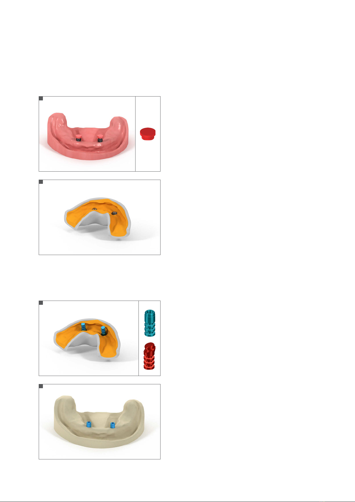
. Procedure in the dental office
.. Selecting Novaloc® Abutment height
2
3
1
* not available for RB/WB.
490.115.indd 2 24/06/2019 14:02
3
.. Impression taking – abutment-level
. Procedure in the dental lab
.. Master cast – abutment-level impression
Step 1 – Placing the Novaloc® Forming/Fixing Matrix
Place the Forming/Fixing Matrix on the Novaloc® Abutment.
Step 2 – Impression taking
Use the mucodynamic technique for impression taking (vinyl poly-
siloxane or polyether rubber).
Send the impression to the dental lab.
Step 1 – Inserting the Novaloc® Model Analog
Insert the Novaloc® Model Analog into the Novaloc® Forming/
Fixing Matrix (see chapter 3 Using the Novaloc® Tools). For
straight abutments use the straight, for angled abutments the
angled analog.
Step 2 – Fabricating the master cast
Pour a master model using standard methods and type-4 dental
stone (DIN 6873).
Note:
The master model can also be created with an implant-level im-
pression.
1
1
2
2
490.115.indd 3 24/06/2019 14:02
4
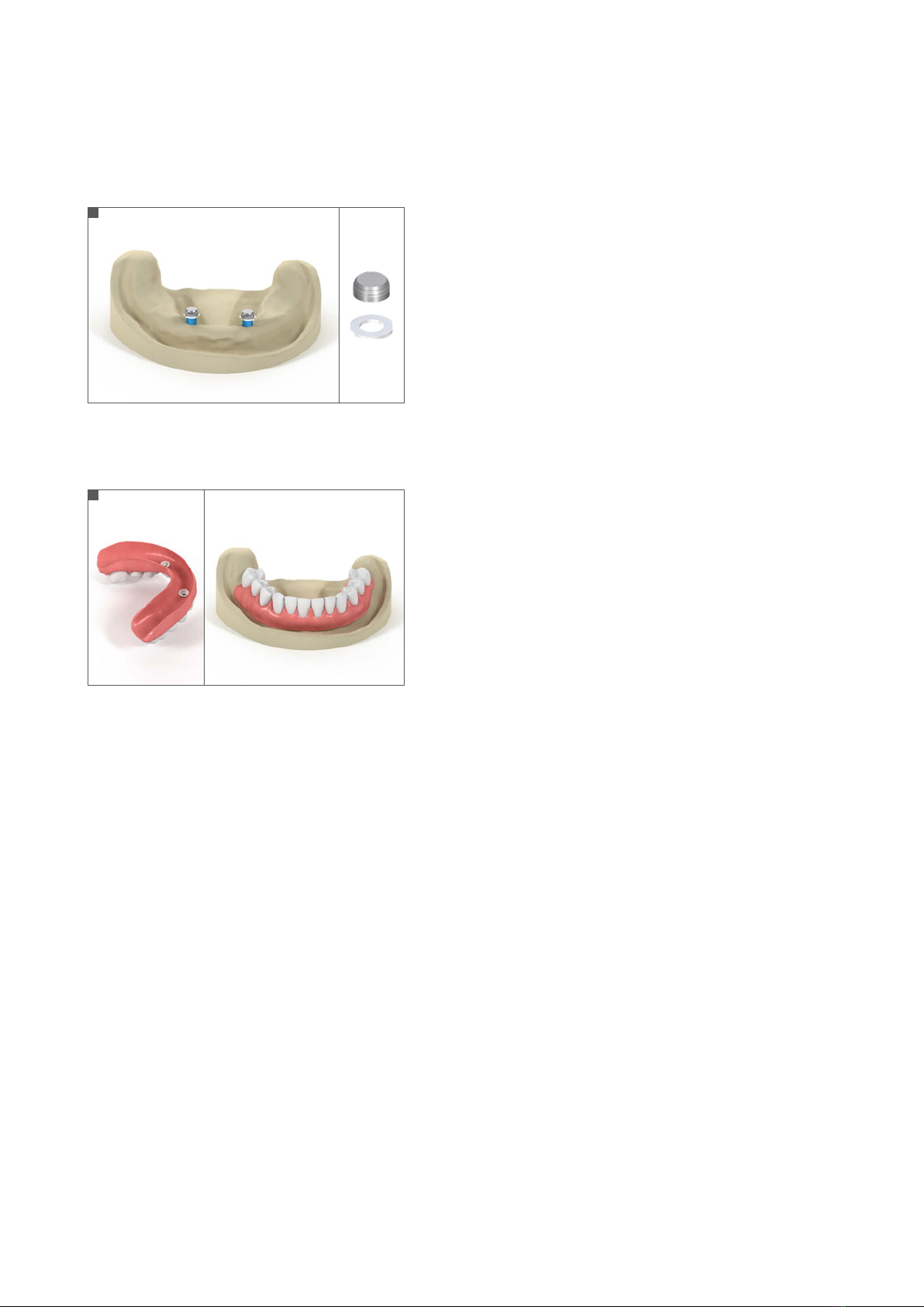
.. Finalizing the new Novaloc® overdenture
Step 1 – Placing the Novaloc® Mounting Collar and
Matrix Housing
Place white Mounting collars on all Novaloc® Model
Analogs.
Place the Matrix Housing incl. preassembled Mounting
Insert onto the Novaloc® Abutments.
Note:
For a chair-side polymerization of the Novaloc® Matrix
Housing use the Novaloc® Processing Spacer to create
the space needed.
Step 2 – Processing the overdenture
Process the overdenture according to standard proce-
dures.
The dental lab will return the finalized Novaloc®
overdenture to the dental office including the Mount-
ing Inserts in place.
1
2
490.115.indd 4 24/06/2019 14:02
5
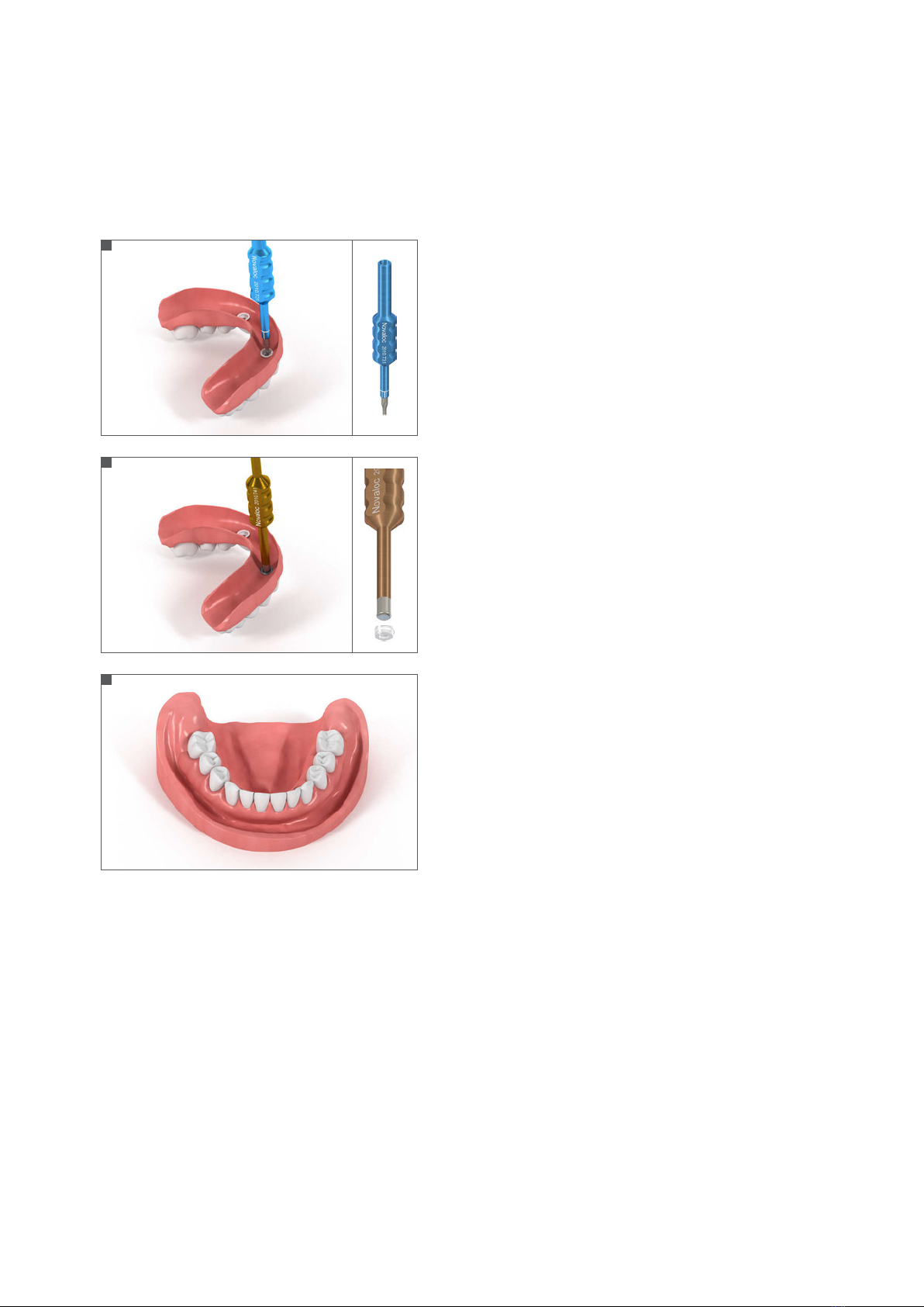
. Procedure in the dental office
.. Seating the new Novaloc® overdenture
Step 1 – Removing the Novaloc® Mounting Insert
Remove all Mounting Inserts from the Matrix Housing
using the Demounting Tool for Mounting Inserts (blue)
(see chapter 3 Using the Novaloc® Tools).
Step 2 – Selecting and inserting the Novaloc®
Retention Inserts
Select the appropriate Novaloc® Retention Insert (see
chapter 4 Special featured Novaloc® components).
Insert the Novaloc® Retention Inserts to the Matrix
Housing using the Mounting and Demounting Tool
for Retention Inserts (brown) (see chapter 3 Using the
Novaloc® Tools).
Step 3 – Seating the finished overdenture
Seat the finished overdenture and check the occlusion.
1
2
3
490.115.indd 5 24/06/2019 14:02
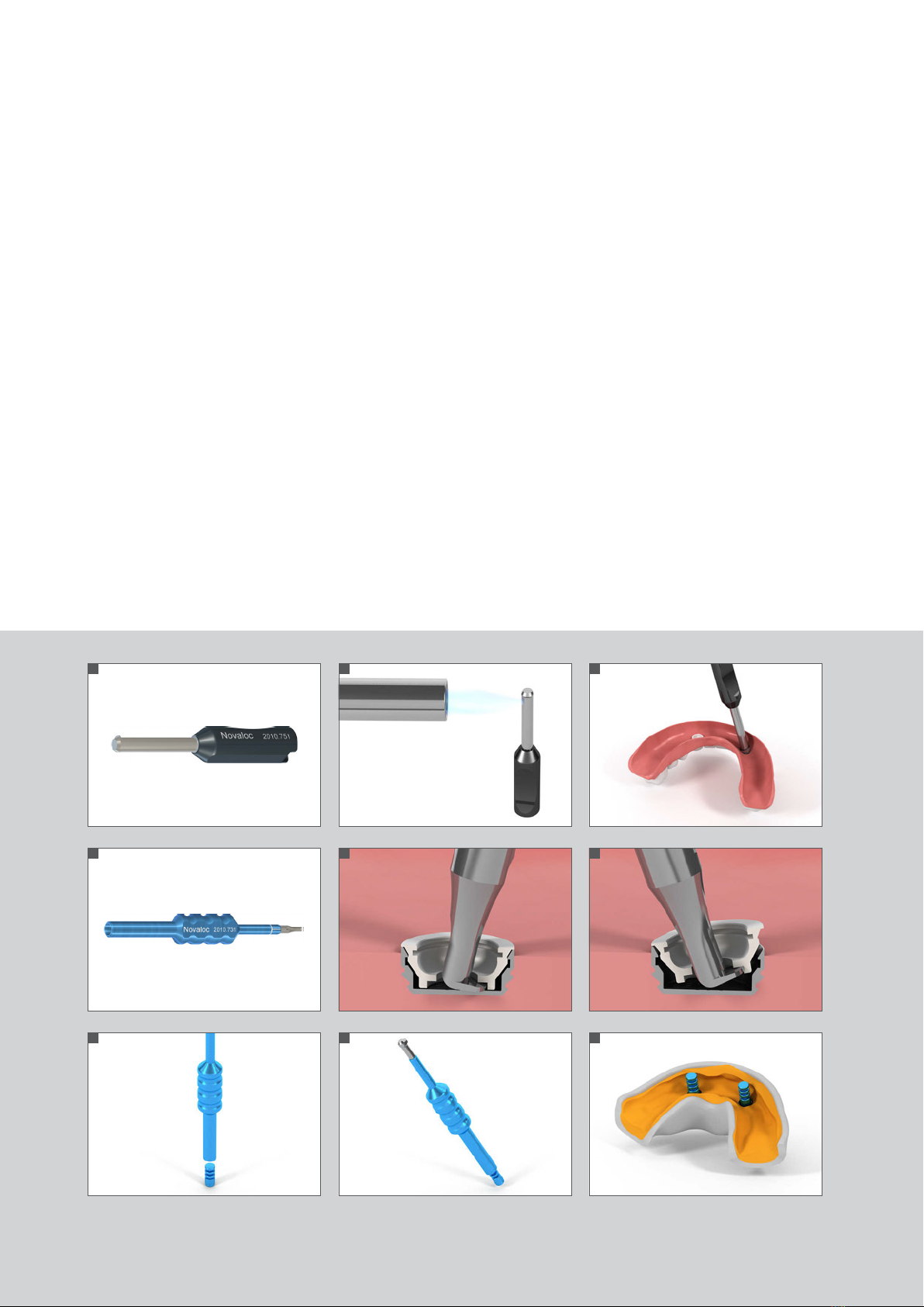
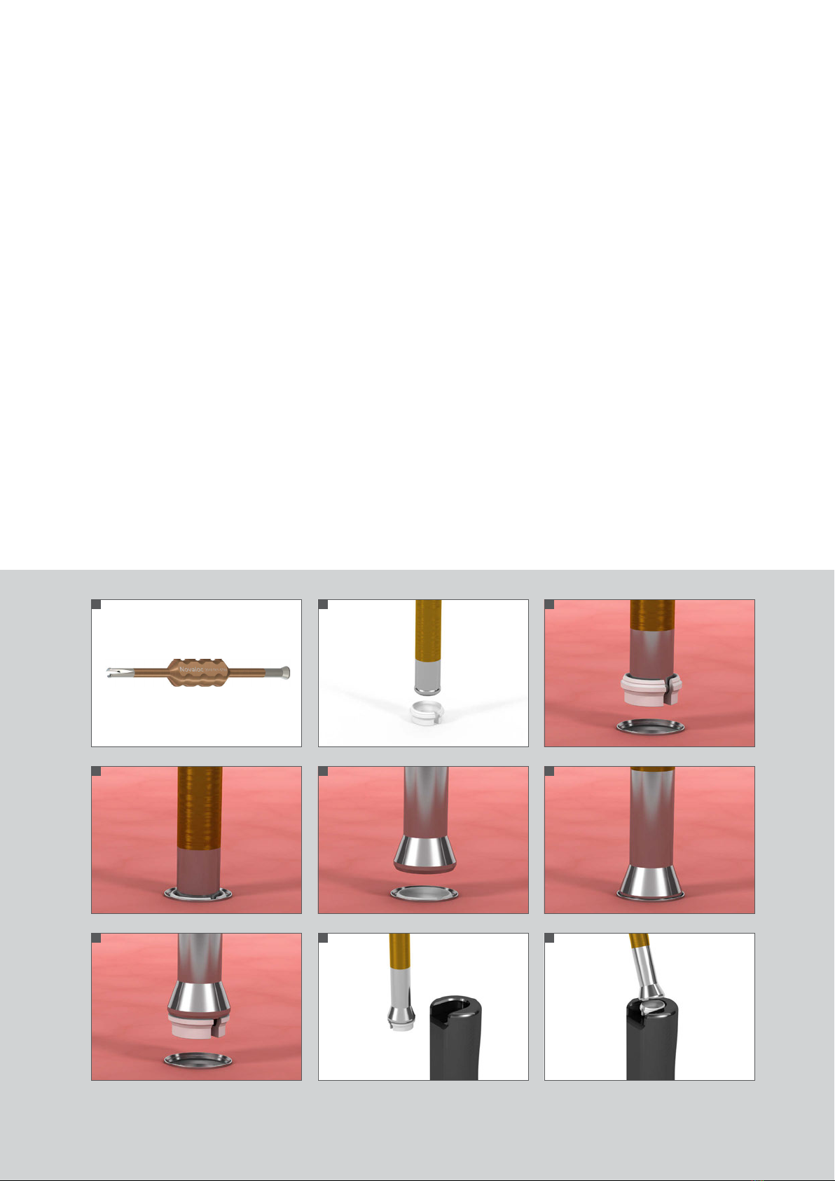
. Using the Novaloc® Tools
. Novaloc® Matrix Housing Extractor (Fig. )
Removing the Novaloc® Matrix Housing from an overdenture
1. Heat the Novaloc® Matrix Housing Extractor head (Fig. 2).
2.
Apply the hot Novaloc® Matrix Housing Extractor to the Matrix Housing and let the heat transfer for 2–3 seconds melting
the resin around the Matrix Housing.
3. Tilt the Novaloc® Matrix Housing Extractor to the opposite side of the beak-shape end in order to remove the Novaloc®
Matrix Housing (Fig. 3).
. Novaloc® Demounting Tool for Mounting Inserts and Model Analog Reposition Aid (Fig. )
Removing the Novaloc® Mounting Insert
1. Insert the toe of the Novaloc® Demounting Tool into the Novaloc® Mounting Insert (Fig. 5).
2. Tip the Novaloc® Demounting Tool to the opposite side of the foot-shaped end and remove the Novaloc® Mounting Insert
from the Novaloc® Matrix Housing (Fig. 6).
Placing the Novaloc® Model Analog
1. Pick up the Novaloc® Model Analog with the opposite side of the Novaloc® Demounting Tool (Fig. 7/8).
2. Position the Novaloc® Model Analog in the impression (Fig. 9).
666666
1
4
7
2
5
8
3
6
9
490.115.indd 6 24/06/2019 14:02
. Novaloc® Mounting and Demounting Tool for
RetentionInserts (Fig. )
Mounting the Novaloc® Retention Insert
1. Pick up the Novaloc® Retention Insert with the gripper end of the Novaloc®
Mounting and Demounting Tool. The Novaloc® Retention Insert will lock on
to the tool (Fig. 12).
2. Place the Novaloc® Retention Insert into the Novaloc® Matrix Housing (Fig. 13).
The Novaloc® Retention Insert “clicks” into position (Fig. 14).
Demounting the Novaloc® Retention Insert
1. Apply the plunger end of the Novaloc® Mounting and Demounting Tool to the
Novaloc® Retention Insert and engage with light pressure (Fig. 15/16).
2. Remove the Novaloc® Retention Insert from the Novaloc® Matrix Housing us-
ing a slight rotational movement (Fig. 17).
3.
Use the special indentation in the handle of the Novaloc® Matrix Housing
Extractor (Fig. 1) to remove the Novaloc® Retention Insert from the Novaloc®
Mounting and Demounting Tool with a tilting movement (Fig. 18/19).
777777
14
11
17
15
12
18
16
13
19
490.115.indd 7 24/06/2019 14:02

8
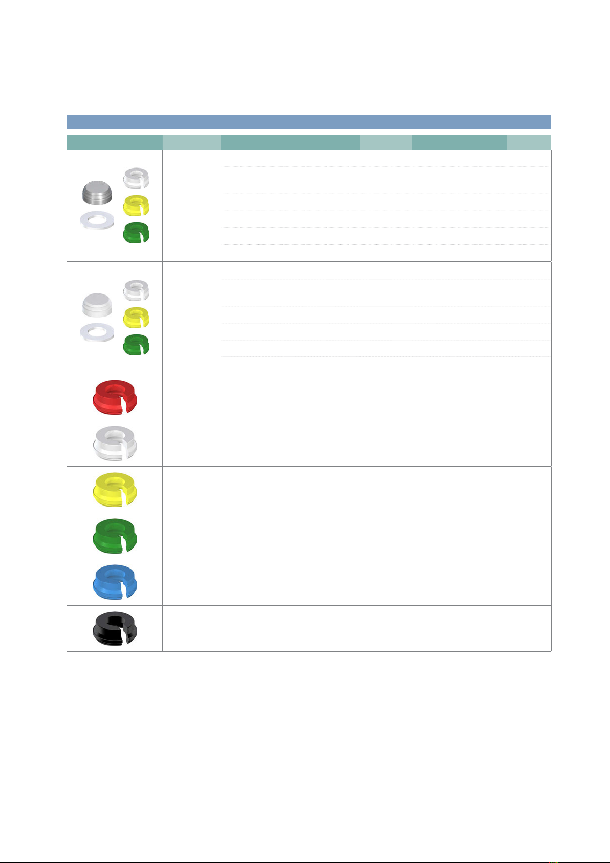
. Special featured Novaloc® Components
Retention insert color Retention
red, extra light approx. 300 g
white, light approx. 750g
yellow, medium approx. 1200 g
green, strong approx. 1650 g
blue, extra-strong approx. 2100 g
black, ultra-strong approx. 2550 g
Novaloc® Retention Inserts
The Novaloc® matrix system allows for a prosthetic insertion of up to
+/-20° divergence, meaning 40° between two Novaloc® Abutments.
Note:
It is recommended to use the light retention force first (white). In
case it feels too loose for the patient, exchange with inserts with a
higher retention force.
Novaloc® Mounting Collar
The Mounting Collar blocks out the area surrounding the abutment,
preventing that resin or a bonding agent flows into the Matrix Hous-
ing and imbedding the abutment.
Novaloc® Matrix Housing, PEEK
The neutral-colored PEEK Matrix Housing is used for extremely labi-
al or buccal implant positions preventing grey irritation coming from
a titanium Matrix Housing.
Novaloc® Matrix Housing with attachment option
This Matrix Housing offers an extended attachment option. It is
used for low-lying abutment heights or in situations requiring more
retention. The attachment may be shortened according the required
height.
Novaloc® Mounting Insert
The Novaloc® Mounting Insert protects the interior of the Novaloc®
Matrix Housing and keeps it in place during processing. Further-
more, it also prevents any resin or bonding agents of entering into
the Novaloc® Matrix Housing during fixation.
Novaloc® Processing Spacer
The Novaloc® Processing Spacer is a placeholder for the Novaloc®
Matrix Housing. It is used for the model-cast, cast metal-reinforced
denture or if the Novaloc® Matrix Housing shall be polymerized into
the overdenture chair-side.
490.115.indd 8 24/06/2019 14:02
9
. Product reference list
ADLC = Amorphous Diamond-Like Carbon
* Manufacturer
Institut Straumann AG
Peter Merian-Weg 12, 4002 Basel
Switzerland
Not all products are available in all countries.
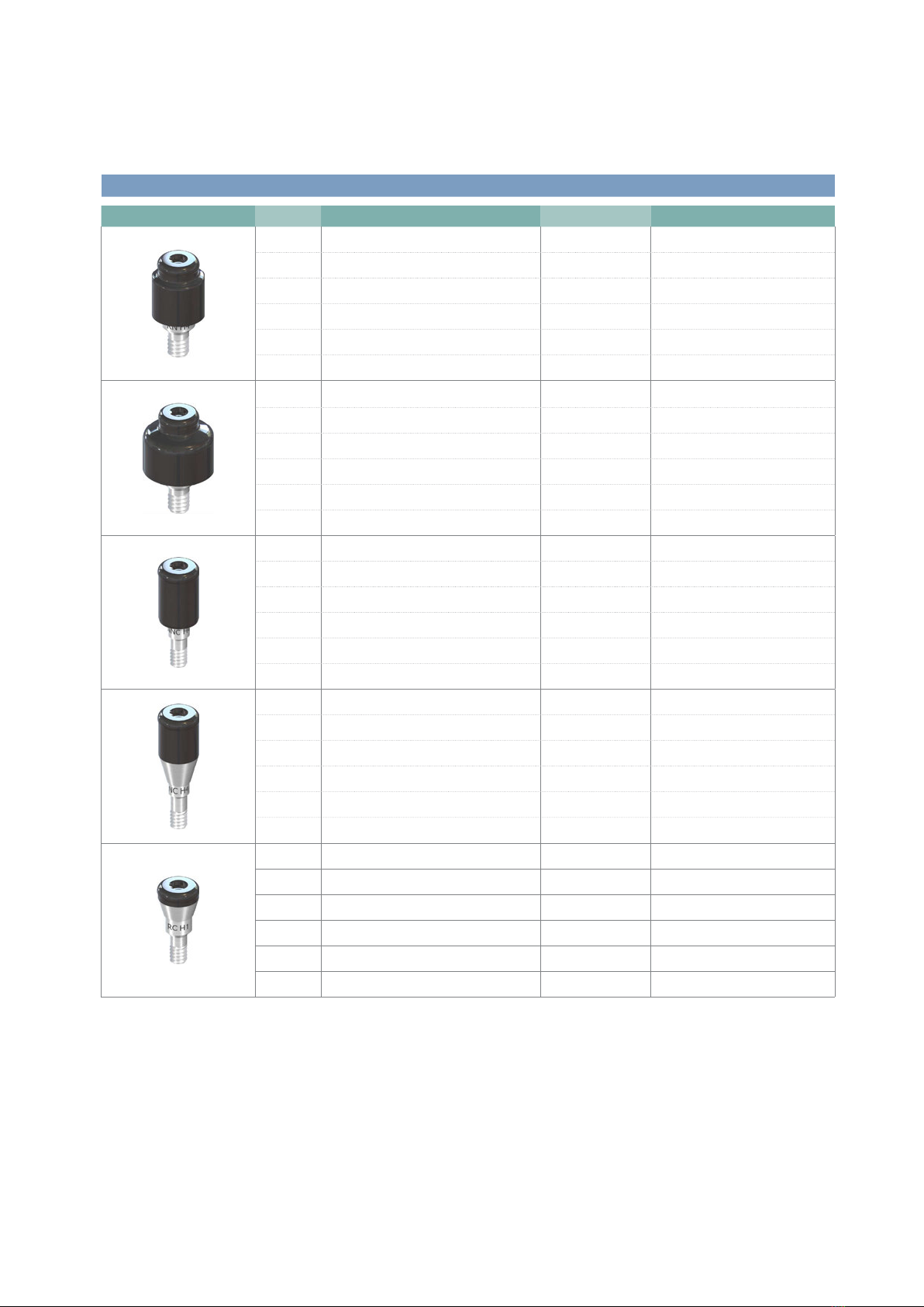
Straumann® Novaloc® Abutment, straight, °*
Art. No. Description Gingiva height Material
048.812 RN Novaloc® Abutment, 0° 1mm Titanium Gr 5/ADLC
048.813 RN Novaloc® Abutment, 0° 2mm Titanium Gr 5/ADLC
048.814 RN Novaloc® Abutment, 0° 3mm Titanium Gr 5/ADLC
048.815 RN Novaloc® Abutment, 0° 4mm Titanium Gr 5/ADLC
048.816 RN Novaloc® Abutment, 0° 5mm Titanium Gr 5/ADLC
048.817 RN Novaloc® Abutment, 0° 6 mm Titanium Gr 5/ADLC
048.818 WN Novaloc® Abutment, 0° 1mm Titanium Gr 5/ADLC
048.819 WN Novaloc® Abutment, 0° 2 mm Titanium Gr 5/ADLC
048.820 WN Novaloc® Abutment, 0° 3mm Titanium Gr 5/ADLC
048.821 WN Novaloc® Abutment, 0° 4mm Titanium Gr 5/ADLC
048.822 WN Novaloc® Abutment, 0° 5mm Titanium Gr 5/ADLC
048.823 WN Novaloc® Abutment, 0° 6mm Titanium Gr 5/ADLC
048.806 NNC Novaloc® Abutment, 0° 1mm Titanium Gr 5/ADLC
048.807 NNC Novaloc® Abutment, 0° 2mm Titanium Gr 5/ADLC
048.808 NNC Novaloc® Abutment, 0° 3mm Titanium Gr 5/ADLC
048.809 NNC Novaloc® Abutment, 0° 4mm Titanium Gr 5/ADLC
048.810 NNC Novaloc® Abutment, 0° 5mm Titanium Gr 5/ADLC
048.811 NNC Novaloc® Abutment, 0° 6mm Titanium Gr 5/ADLC
022.0046 NC Novaloc® Abutment, 0° 1mm Titanium Gr 5/ADLC
022.0047 NC Novaloc® Abutment, 0° 2mm Titanium Gr 5/ADLC
022.0048 NC Novaloc® Abutment, 0° 3mm Titanium Gr 5/ADLC
022.0049 NC Novaloc® Abutment, 0° 4mm Titanium Gr 5/ADLC
022.0050 NC Novaloc® Abutment, 0° 5 mm Titanium Gr 5/ADLC
022.0051 NC Novaloc® Abutment, 0° 6mm Titanium Gr 5/ADLC
022.0052 RC Novaloc® Abutment, 0° 1mm Titanium Gr 5/ADLC
022.0053 RC Novaloc® Abutment, 0° 2mm Titanium Gr 5/ADLC
022.0054 RC Novaloc® Abutment, 0° 3mm Titanium Gr 5/ADLC
022.0055 RC Novaloc® Abutment, 0° 4 mm Titanium Gr 5/ADLC
022.0056 RC Novaloc® Abutment, 0° 5 mm Titanium Gr 5/ADLC
022.0057 RC Novaloc® Abutment, 0° 6mm Titanium Gr 5/ADLC
490.115.indd 9 24/06/2019 14:02
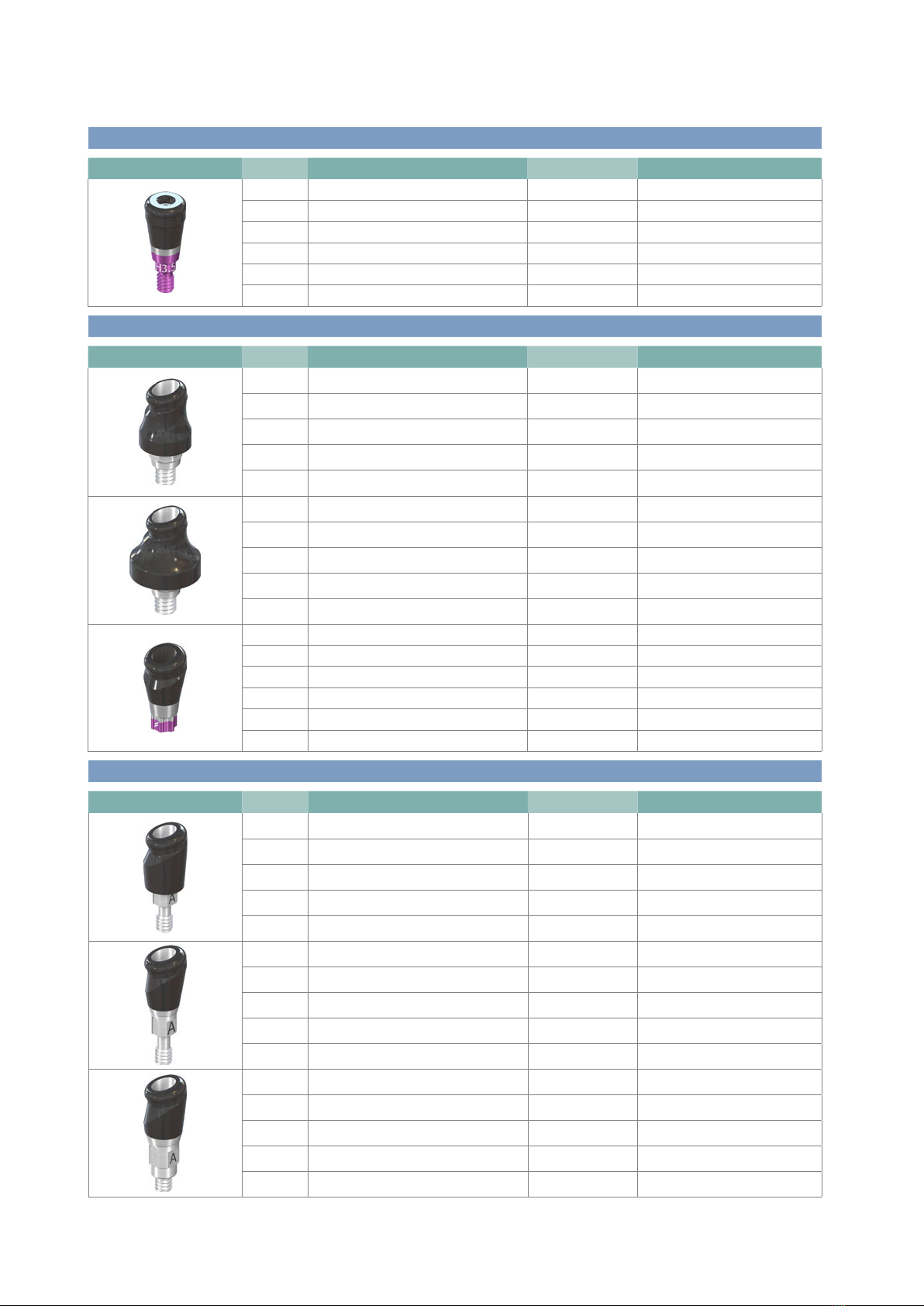
Straumann® Novaloc® Abutment, angled, °*
Art. No. Description Gingiva height Material
048.832 RN Novaloc® Abutment, 15° 2mm Titanium Gr 5/ADLC
048.833 RN Novaloc® Abutment, 15° 3mm Titanium Gr 5/ADLC
048.834 RN Novaloc® Abutment, 15° 4mm Titanium Gr 5/ADLC
048.835 RN Novaloc® Abutment, 15° 5mm Titanium Gr 5/ADLC
048.836 RN Novaloc® Abutment, 15° 6mm Titanium Gr 5/ADLC
048.837 WN Novaloc® Abutment, 15° 2mm Titanium Gr 5/ADLC
048.838 WN Novaloc® Abutment, 15° 3 mm Titanium Gr 5/ADLC
048.839 WN Novaloc® Abutment, 15° 4 mm Titanium Gr 5/ADLC
048.840 WN Novaloc® Abutment, 15° 5mm Titanium Gr 5/ADLC
048.841 WN Novaloc® Abutment, 15° 6mm Titanium Gr 5/ADLC
062.4507 RB/WB Novaloc® Abutment ∅3.8, 15° 2.5 mm Titanium Gr 5/ADLC
062.4508 RB/WB Novaloc® Abutment ∅3.8, 15° 3.5 mm Titanium Gr 5/ADLC
062.4509 RB/WB Novaloc® Abutment ∅3.8, 15° 4.5 mm Titanium Gr 5/ADLC
062.4510 RB/WB Novaloc® Abutment ∅3.8, 15° 5.5 mm Titanium Gr 5/ADLC
062.4511 RB/WB Novaloc® Abutment ∅3.8, 15° 6.5 mm Titanium Gr 5/ADLC
062.4512 RB/WB Novaloc® Abutment ∅3.8, 15° 7.5 mm Titanium Gr 5/ADLC
10
Straumann® Novaloc® Abutment, straight, °*
Art. No. Description Gingiva height Material
062.4501 RB/WB Novaloc® Abutment ∅3.8, 0° 1.5 mm Titanium Gr 5/ADLC
062.4502 RB/WB Novaloc® Abutment ∅3.8, 0° 2.5 mm Titanium Gr 5/ADLC
062.4503 RB/WB Novaloc® Abutment ∅3.8, 0° 3.5 mm Titanium Gr 5/ADLC
062.4504 RB/WB Novaloc® Abutment, ∅3.8, 0° 4.5 mm Titanium Gr 5/ADLC
062.4505 RB/WB Novaloc® Abutment ∅3.8, 0° 5.5 mm Titanium Gr 5/ADLC
062.4506 RB/WB Novaloc® Abutment ∅3.8, 0° 6.5 mm Titanium Gr 5/ADLC
Straumann® Novaloc® Abutment, angled, ° | Type A*
Art. No. Description Gingiva height Material
048.842 NNC Novaloc® Abutment, 15° 2mm Titanium Gr 5/ADLC
048.843 NNC Novaloc® Abutment, 15° 3mm Titanium Gr 5/ADLC
048.844 NNC Novaloc® Abutment, 15° 4mm Titanium Gr 5/ADLC
048.845 NNC Novaloc® Abutment, 15° 5mm Titanium Gr 5/ADLC
048.846 NNC Novaloc® Abutment, 15° 6mm Titanium Gr 5/ADLC
022.0062 NC Novaloc® Abutment, 15° 2mm Titanium Gr 5/ADLC
022.0063 NC Novaloc® Abutment, 15° 3mm Titanium Gr 5/ADLC
022.0064 NC Novaloc® Abutment, 15° 4mm Titanium Gr 5/ADLC
022.0065 NC Novaloc® Abutment, 15° 5mm Titanium Gr 5/ADLC
022.0066 NC Novaloc® Abutment, 15° 6 mm Titanium Gr 5/ADLC
022.0067 RC Novaloc® Abutment, 15° 2mm Titanium Gr 5/ADLC
022.0068 RC Novaloc® Abutment, 15° 3mm Titanium Gr 5/ADLC
022.0069 RC Novaloc® Abutment, 15° 4mm Titanium Gr 5/ADLC
022.0070 RC Novaloc® Abutment, 15° 5mm Titanium Gr 5/ADLC
022.0071 RC Novaloc® Abutment, 15° 6mm Titanium Gr 5/ADLC
490.115.indd 10 24/06/2019 14:02
11
ADLC = Amorphous Diamond-Like Carbon
* Manufacturer
Institut Straumann AG
Peter Merian-Weg 12, 4002 Basel
Switzerland
Not all products are available in all countries.
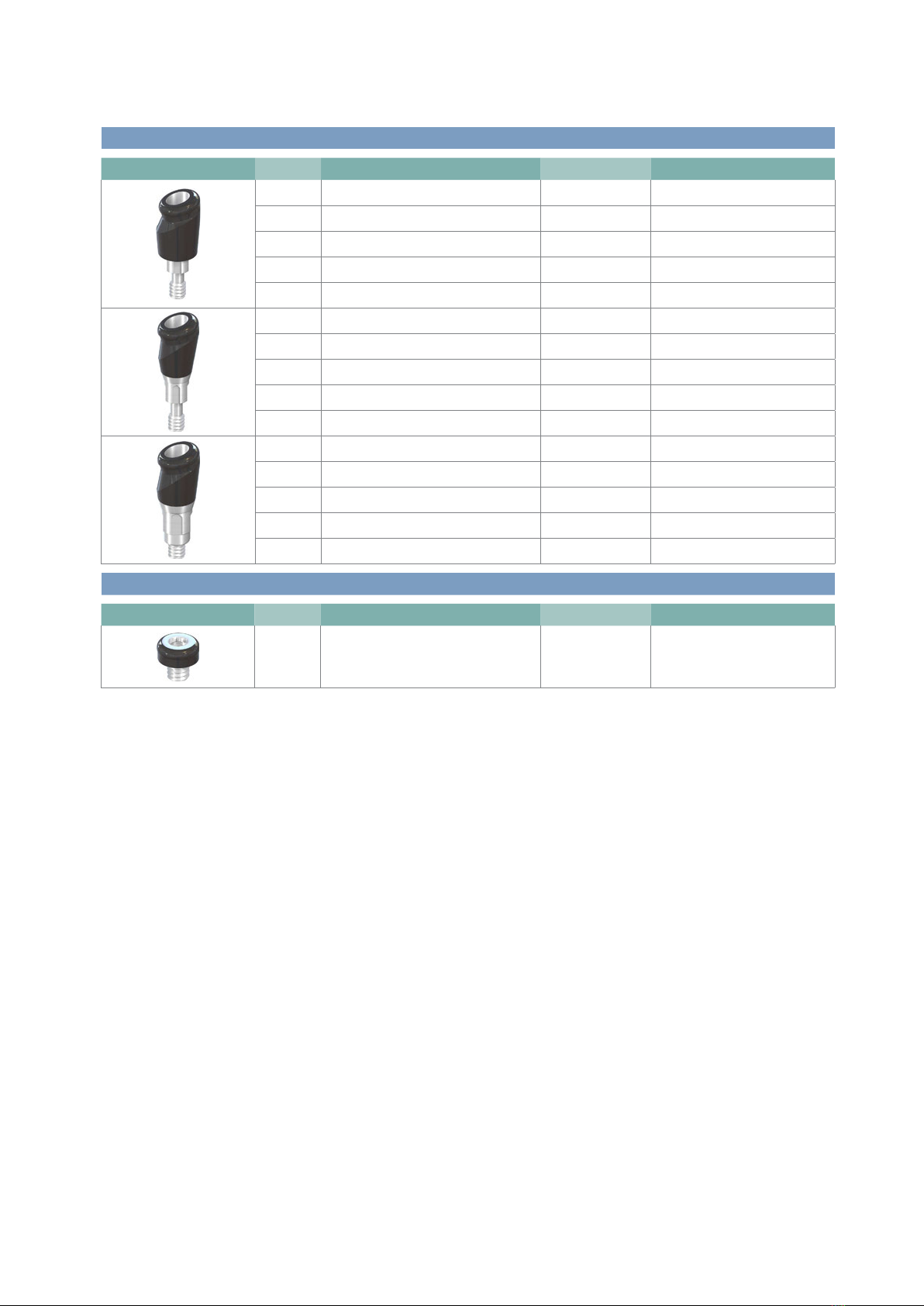
Straumann® Novaloc® Abutment, angled, ° | Type B*
Art. No. Description Gingiva height Material
048.847 NNC Novaloc® Abutment, 15° 2mm Titanium Gr 5/ADLC
048.848 NNC Novaloc® Abutment, 15° 3mm Titanium Gr 5/ADLC
048.849 NNC Novaloc® Abutment, 15° 4mm Titanium Gr 5/ADLC
048.850 NNC Novaloc® Abutment, 15° 5mm Titanium Gr 5/ADLC
048.851 NNC Novaloc® Abutment, 15° 6mm Titanium Gr 5/ADLC
022.0072 NC Novaloc® Abutment, 15° 2 mm Titanium Gr 5/ADLC
022.0073 NC Novaloc® Abutment, 15° 3 mm Titanium Gr 5/ADLC
022.0074 NC Novaloc® Abutment, 15° 4 mm Titanium Gr 5/ADLC
022.0075 NC Novaloc® Abutment, 15° 5 mm Titanium Gr 5/ADLC
022.0076 NC Novaloc® Abutment, 15° 6 mm Titanium Gr 5/ADLC
022.0077 RC Novaloc® Abutment, 15° 2mm Titanium Gr 5/ADLC
022.0078 RC Novaloc® Abutment, 15° 3mm Titanium Gr 5/ADLC
022.0079 RC Novaloc® Abutment, 15° 4mm Titanium Gr 5/ADLC
022.0080 RC Novaloc® Abutment, 15° 5mm Titanium Gr 5/ADLC
022.0081 RC Novaloc® Abutment, 15° 6mm Titanium Gr 5/ADLC
Straumann® Novaloc® Bar Abutment
Art. No. Description Gingiva height Material
048.857V2 Novaloc® Bar Abutment N/A Titanium Gr 5/ADLC
490.115.indd 11 24/06/2019 14:02

12
ADLC = Amorphous Diamond-Like Carbon
Not all products are available in all countries.
*compatible to LOCATOR®
Straumann® Novaloc® Plan Abutments, straight, °
Art. No. Description Compatility to Novaloc® Abtuments
048.280V4* RN Novaloc® Plan Abutment, H 1-6 mm, POM 048.812, 048.813, 048.814, 048.815, 048.816, 048.817
048.852V4* WN Novaloc® Plan Abutment, H 1-6 mm, POM 048.818, 048.819, 048.820, 048.821, 048.822, 048.823
048.951V4* NNC Novaloc® Plan Abutment, H 1-6 mm, POM 048.806, 048.807, 048.808, 048.809, 048.810, 048.811
025.2646-04* NC Novaloc® Plan Abutment, H 1-6 mm, POM 022.0046, 022.0047, 022.0048, 022.0049, 022.0050
025.4646-04* RC Novaloc® Plan Abutment, H 1-6 mm, POM 022.0052, 022.0053, 022.0054, 022.0055, 022.0056, 022.0057
Straumann® Novaloc® Plan Abutments, angled, °, Type A
Art. No. Description Compatility to Novaloc® Abtuments
048.855V4 NNC Novaloc® Plan Abutment, angled 15°,
H2-6mm, type A, POM
048.842, 048.843, 048.844, 048.845, 048.846
025.0046V4 NC Novaloc® Plan Abutment, angled 15°,
H2-6mm, type A, POM
022.0062, 022.0063, 022.0064, 022.0065, 022.0066
025.0045V4 RC Novaloc® Plan Abutment, angled 15°,
H2-6mm, type A, POM
022.0067, 022.0068, 022.0069, 022.0070, 022.0071
Straumann® Novaloc® Plan Abutments, angled, °, Type B
Art. No. Description Compatility to Novaloc® Abtuments
048.856V4 NNC Novaloc® Plan Abutment, angled 15°,
H2-6mm, type B, POM
048.847, 048.848, 048.849, 048.850, 048.851
025.0048V4 NC Novaloc® Plan Abutment, angled 15°,
H2-6mm, type B, POM
022.0072, 022.0073, 022.0074, 022.0075, 022.0076
025.0047V4 RC Novaloc® Plan Abutment, angled 15°,
H2-6mm, type B, POM
022.0077, 022.0078, 022.0079, 022.0080, 022.0081
Straumann® Novaloc® Plan Abutments, angled, °
Art. No. Description Compatility to Novaloc® Abtuments
048.853V4 RN Novaloc® Plan Abutment, angled 15°,
H2-6mm, POM
048.832, 048.833, 048.834, 048.835, 048.836
048.854V4 WN Novaloc® Plan Abutment, angled 15°,
H2-6mm, POM
048.837, 048.838, 048.839, 048.840, 048.841
490.115.indd 12 24/06/2019 14:02
13
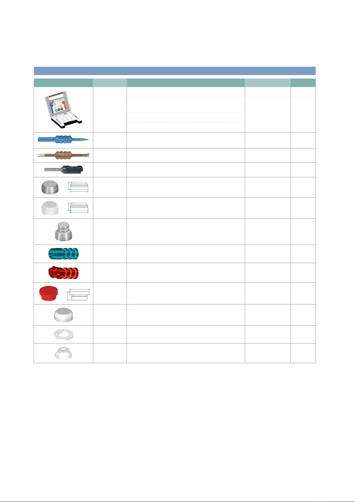
Retention Inserts*
Art. No. Description Material Retention Quantity
2010.601-STM Processing Package titanium
Titanium Matrix Housing
(includingMounting Insert)
Titanium /
PEEK
2 pcs
Retention Insert, white, light PEEK Light, approx. 750g 2 pcs
Retention Insert, yellow, medium PEEK Medium, approx. 1200g 2 pcs
Retention Insert, green, strong PEEK Strong, approx. 1650g 2 pcs
Mounting Collar, silicone Silicone 2 pcs
2010.611-STM Processing Package PEEK
PEEK Matrix Housing
(includingMountingInsert)
PEEK 2 pcs
Retention Insert, white, light PEEK Light, approx. 750g 2 pcs
Retention Insert, yellow, medium PEEK Medium, approx. 1200g 2 pcs
Retention Insert, green, strong PEEK Strong, approx. 1650g 2 pcs
Mounting Collar, silicone Silicone 2 pcs
2010.710-STM Novaloc® Retention Insert, red PEEK Extra-light, approx. 300g 4 pcs
2010.711-STM Novaloc® Retention Insert, white PEEK Light, approx. 750g 4 pcs
2010.712-STM Novaloc® Retention Insert, yellow PEEK Medium, approx. 1200g 4 pcs
2010.713-STM Novaloc® Retention Insert, green PEEK Strong, approx. 1650g 4 pcs
2010.714-STM Novaloc® Retention Insert, blue PEEK Extra-strong, approx.
2100g
4 pcs
2010.715-STM Novaloc® Retention Insert, black PEEK Ultra-strong, approx.
2550g
4 pcs
CE 0481
* Manufacturer
Valoc AG
Theodorshofweg 22, 4310 Rheinfelden
Switzerland
* Distributor
Institut Straumann AG
Peter Merian-Weg 12, 4002 Basel
Switzerland
490.115.indd 13 24/06/2019 14:02
14
Auxiliaries*
Art. No. Description Material Quantity
2010.101-STM Equipment Box, incl. tools
Demounting Tool for Mounting Insert and Model Analog
Reposition Aid (blue)
Aluminum/steel
Mounting and Demounting Tool for Retention Inserts (brown)
Matrix Housing Extractor (gray)
2010.731-STM Demounting Tool for Mounting Inserts an Model Analog
Reposition Aid (blue)
Aluminum/steel 1 pcs
2010.741-STM Mounting and Demounting Tool for Retention Inserts (brown) Aluminum/steel 1 pcs
2010.751-STM Matrix Housing Extractor (gray) Aluminum/steel 1 pcs
∅ 5.5
2.3
2010.701-STM Matrix Housing, titanium (including Mounting Insert) Titanium / PEEK 4 pcs
∅ 5.5
2.3
2010.702-STM Matrix Housing, PEEK (including Mounting Insert) PEEK 4 pcs
2010.703-STM Matrix Housing with attachment option
(including Mounting Insert)
Titanium / PEEK 4 pcs
2010.721-STM Model Analog, blue Aluminum 4 pcs
2010.720-STM Model analogue, angled 15°, red Aluminum 4 pcs
2.5
∅ 5.9
2010.722-STM Forming/Fixing Matrix, red PEEK 4 pcs
2010.723-STM Processing Spacer, white POM 4 pcs
2010.724-STM Mounting Collar Silicone 10 pcs
2010.725-STM Mounting Insert PEEK 4 pcs
CE 0481
* Manufacturer
Valoc AG
Theodorshofweg 22, 4310 Rheinfelden
Switzerland
* Distributor
Institut Straumann AG
Peter Merian-Weg 12, 4002 Basel
Switzerland
490.115.indd 14 24/06/2019 14:02
15
. Appendix
. Appendix A
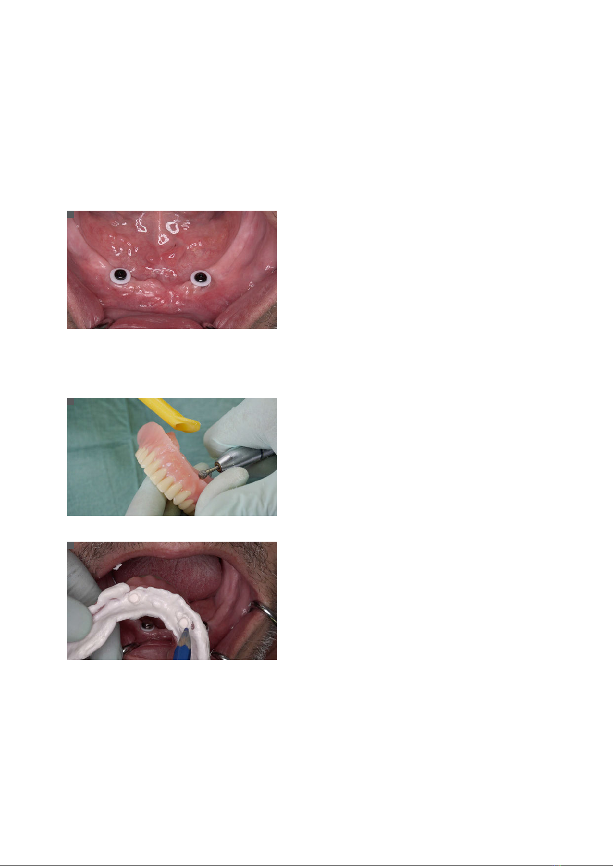
.. Chair-side modification of an existing lower denture into an overdenture supported by Novaloc® Abutments
For an existing well-fitting and well-functioning lower complete denture, the Novaloc® Retentive System can be used in a
chair-side procedure.
Caution: It is a prerequisite however, that the lower complete denture does not need to be relined by a dental technician.
Place white Mounting Collars on each Novaloc® Abutment. The
Mounting Collars are used to block out the area surrounding the
abutments.
Caution: If the Novaloc® Mounting Collars do not completely fill the
space between the mucosa and the Matrix Housings any remaining
undercuts must be blocked out to prevent resin flowing under the
Matrix Housings. This can be accomplished by stacking two or more
Mounting Collars or a custom sized and pierced piece of rubber dam.
Then place a Matrix Housing with white Mounting Insert onto each
Novaloc® Abutment, leaving the white Mounting Collar beneath it.
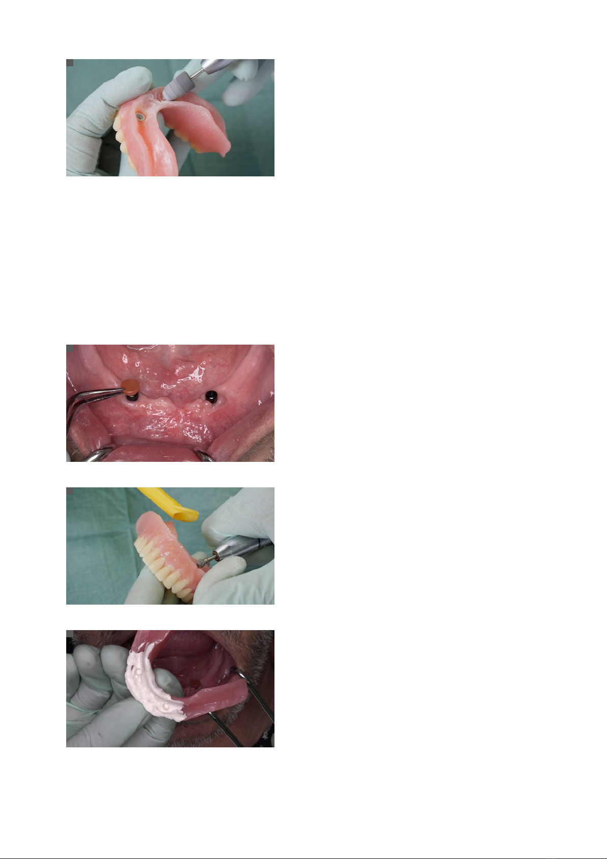
Prepare the lower complete denture to accommodate the Novaloc®
Matrix Housings. Hollow out the existing denture base in the areas
of the Novaloc® Matrix Housings with handpiece and resin bur.
Note: Novaloc® Processing Spacers can be used instead of Matrix
Housings to create the space needed in the denture.
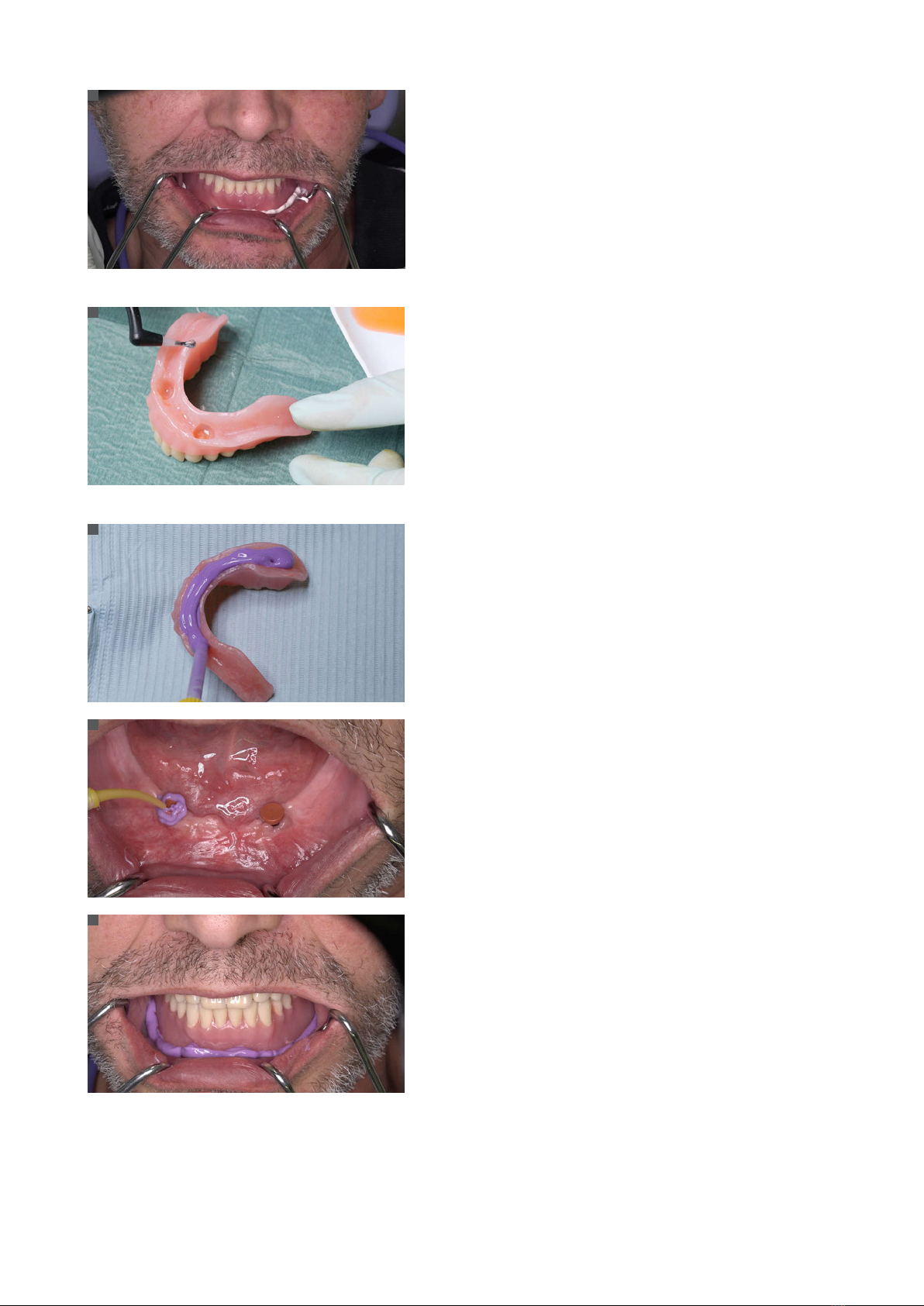
Use wash impression silicone to confirm adequate clearance be-
tween the Matrix Housings and the denture base.
1
2
3
490.115.indd 15 24/06/2019 14:02
16
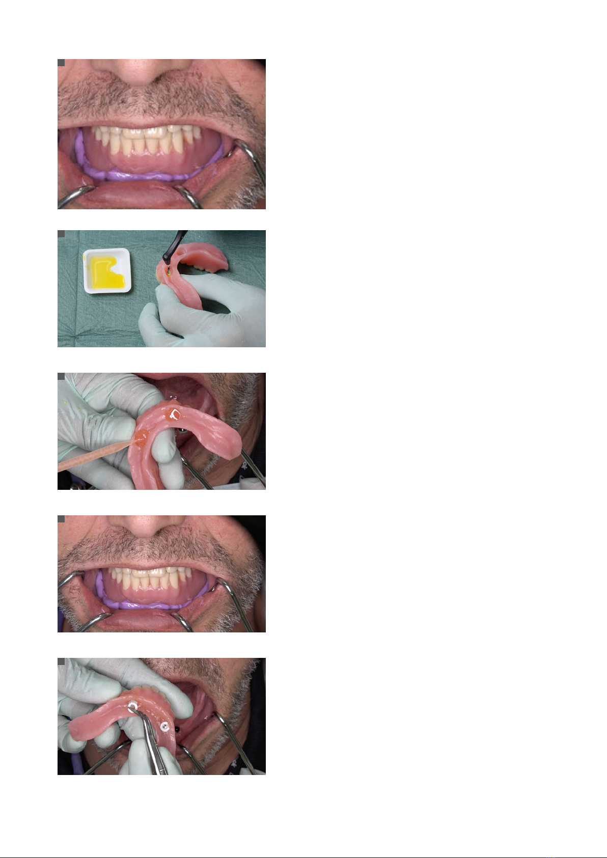
Insert the lower complete denture into the patient’s mouth and
check the clearance. The Matrix Housings fixed on the abutments
should not touch the denture base. Reconfirm adequate space using
wash impression silicone. Adjust the denture base until seated pas-
sively in occlusion without touching the Matrix Housings.
Prepare the recess in the lower complete denture with monomer.
Protect areas where you don’t want the resin with a thin layer of
petroleum jelly.
Fill the hollowed area with self-curing PMMA resin to polymerize the
Matrix Housings in the denture.
Apply a small amount of acrylic resin to the recess of the denture
base and around the Matrix Housings. Insert the lower complete
denture into the oral cavity.
Once the lower complete denture is properly seated, maintain the
patient in full occlusion while the acrylic sets.
Once the resin has cured, remove the lower complete denture from
the mouth and discard the white Novaloc® Mounting Collars.
Put the lower complete denture in hot, but not boiling, water. Place
it in a pressure pot when available.
4
5
6
7
8
490.115.indd 16 24/06/2019 14:02
17
After final curing, remove any excess acrylic and finish the denture
base.
Exchange the Mounting Inserts for the final Novaloc® Retention
Inserts and insert the final overdenture into the patient’s mouth. For
details see brochure Basic Information on the Straumann® Novaloc®
Retentive System for Hybrid Dentures (490.115).
9
. Appendix B
.. Preparation for lab-side modification of an existing lower denture into an overdenture supported by Novaloc®
Abutments
If the lower complete denture’s fit is inadequate (poor adaptation to underlying tissue) after surgery and major adjustments
are necessary, indirect relining of the mandibular denture is necessary. This means that relining and insertion of Novaloc®
Matrix Housings incl. Mounting Inserts are performed by the dental technician immediately after border mold impres-
sion-taking. Lab-side relining has to be planned in advance with your dental technician.
Place a Novaloc® Forming/Fixing Matrix onto each Novaloc® Abut-
ment.
Hollow out the existing denture base in the areas of the Novaloc®
Forming/Fixing Matrices with handpiece and resin bur.
Use wash impression silicone to confirm adequate clearance be-
tween the Matrix Housings and the denture base.
10
11
12
490.115.indd 17 24/06/2019 14:02
18
Insert the lower complete denture into the patient’s mouth and
check the clearance. The Matrix Housings on the abutments should
not touch the denture base. Reconfirm space using wash impression
silicone. Adjust the denture base to seat passively in occlusion with-
out touching the Matrix Housings.
Prepare the lower complete denture for border mold impression
technique.
Remove any undercuts from the denture base.
Check for peripheral extensions and if necessary (optional) adjust
them with thermo-plastic materials (border molding).
Dry the inner surface of the mandibular denture with alcohol and
apply the corresponding adhesive.
Take a reline impression.
Apply polyether impression material to the internal aspect of the
lower complete denture, and take a reline impression with the pa-
tient in occlusion.
13
14
15
16
17
490.115.indd 18 24/06/2019 14:02
Table of contents
Other Straumann Dental Equipment manuals


Popular Dental Equipment manuals by other brands

Biolase
Biolase Waterlase iPlus user manual

KaVo
KaVo ProXam iS Instructions for use

HAGER & WERKEN
HAGER & WERKEN MIRAHOLD-BLOCK Instructions for use

KMD technology
KMD technology Gema Scaler Sonic operating instructions

DENTSPLY
DENTSPLY Cavitron Directions for use

Aseptico
Aseptico AEU-500 Operation and maintenance instruction manual

Owandy Radiology
Owandy Radiology RX-DC user manual

Bio-Art
Bio-Art LUPA instruction manual

Aseptico
Aseptico ADU-17X Express II Operation and maintenance instruction manual

NSK
NSK Ti-Max NLX nano Operation manual

Dentsply Sirona
Dentsply Sirona X-Smart user manual

orangedental
orangedental opt-on 2.7 Instructions for use


