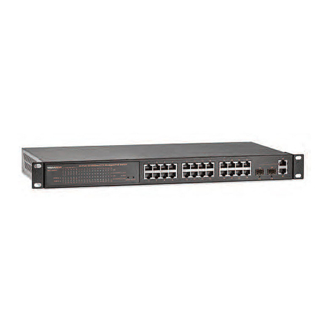
Force 10 S2410 Instruction Manual

August 2007
Installing the S2410 System

Copyright 2007 Force10 Networks®
All rights reserved. Printed in the USA. August 2007.
Force10 Networks reserves the right to change, modify, revise this publication without notice.
Trademarks
Copyright 2007 by Force10 Networks, Inc. All rights reserved. Force10 Networks and E-Series are registered trademarks of Force10
Networks, Inc. Force10, the Force10 logo, E1200, E600, E600i, E300, EtherScale, TeraScale, and FTOS are trademarks of Force10
Networks, Inc. All other brand and product names are registered trademarks or trademarks of their respective holders.
Statement of Conditions
In the interest of improving internal design, operational function, and/or reliability, Force10 Networks reserves the right to make changes to
products described in this document without notice. Force10 Networks does not assume any liability that may occur due to the use or
application of the product(s) described herein.
USA Federal Communications Commission (FCC) Statement
This equipment has been tested and found to comply with the limits for a Class A digital device, pursuant to Part 15 of the FCC rules. These
limits are designated to provide reasonable protection against harmful interference when the equipment is operated in a commercial
environment. This equipment generates, uses, and can radiate radio frequency energy. If it is not installed and used in accordance to the
instructions, it may cause harmful interference to radio communications.
Operation of this equipment in a residential area is likely to cause harmful interference, in which case users will be required to take whatever
measures necessary to correct the interference at their own expense.
Canadian Department of Communication Statement
The digital apparatus does not exceed the Class A limits for radio noise emissions from digital apparatus set out in the Radio Interference
Regulations of the Canadian Department of Communications.
Attention: Le present appareil numerique n’ emet pas de perturbations radioelectriques depassant les normes applicables aux appareils
numeriques de la Class A prescrites dans le Reglement sur les interferences radioelectriques etabli par le ministere des Communications du
Canada.
VCCI Compliance for Class A Equipment (Japan)
This is Class A product based on the standard of the Voluntary Control Council For Interference by Information Technology Equipment
(VCCI). If this equipment is used in a domestic environment, radio disturbance may arise. When such trouble occurs, the user may be
required to take corrective actions.\
Caution: This device is a Class A product. In a domestic environment, this device can cause radio
interference, in which case, the user may be required to take appropriate measures.
Danger: AC Power cords are for use with Force10 Networks equipment only, do not use Force10
Networks AC Power cords with any unauthorized hardware.

Installing the S2410 System 3
Contents . . . . . . . . . . . . . . . . . . . . . . . . . . . . . . . . . . . . . . . . . . . . . . . . . . . . . . . . . . . . . . . . . . . 3
Preface
About this Guide . . . . . . . . . . . . . . . . . . . . . . . . . . . . . . . . . . . . . . . . . . . . . . . . . . . . . . . . . . . . 5
Information Symbols . . . . . . . . . . . . . . . . . . . . . . . . . . . . . . . . . . . . . . . . . . . . . . . . . . . . . . . . . . . . . . 5
Related Publications . . . . . . . . . . . . . . . . . . . . . . . . . . . . . . . . . . . . . . . . . . . . . . . . . . . . . . . . . . . . . . 6
Chapter 1
The S2410 System . . . . . . . . . . . . . . . . . . . . . . . . . . . . . . . . . . . . . . . . . . . . . . . . . . . . . . . . . . . 7
Physical Interfaces . . . . . . . . . . . . . . . . . . . . . . . . . . . . . . . . . . . . . . . . . . . . . . . . . . . . . . . . . . . . . . . 7
Required Equipment . . . . . . . . . . . . . . . . . . . . . . . . . . . . . . . . . . . . . . . . . . . . . . . . . . . . . . . . . . . . . . 8
Features . . . . . . . . . . . . . . . . . . . . . . . . . . . . . . . . . . . . . . . . . . . . . . . . . . . . . . . . . . . . . . . . . . . . . . . 8
Ports . . . . . . . . . . . . . . . . . . . . . . . . . . . . . . . . . . . . . . . . . . . . . . . . . . . . . . . . . . . . . . . . . . . . . . . . . . 8
System Status . . . . . . . . . . . . . . . . . . . . . . . . . . . . . . . . . . . . . . . . . . . . . . . . . . . . . . . . . . . . . . . . . . . 9
LED Displays . . . . . . . . . . . . . . . . . . . . . . . . . . . . . . . . . . . . . . . . . . . . . . . . . . . . . . . . . . . . . . . . 9
Chapter 2
Site Preparation . . . . . . . . . . . . . . . . . . . . . . . . . . . . . . . . . . . . . . . . . . . . . . . . . . . . . . . . . . . . 11
Site Selection . . . . . . . . . . . . . . . . . . . . . . . . . . . . . . . . . . . . . . . . . . . . . . . . . . . . . . . . . . . . . . . . . . . .11
Cabinet Placement . . . . . . . . . . . . . . . . . . . . . . . . . . . . . . . . . . . . . . . . . . . . . . . . . . . . . . . . . . . . . . 12
Rack Mounting . . . . . . . . . . . . . . . . . . . . . . . . . . . . . . . . . . . . . . . . . . . . . . . . . . . . . . . . . . . . . . . . . . 12
Fans and Airflow . . . . . . . . . . . . . . . . . . . . . . . . . . . . . . . . . . . . . . . . . . . . . . . . . . . . . . . . . . . . . . . . 12
Power . . . . . . . . . . . . . . . . . . . . . . . . . . . . . . . . . . . . . . . . . . . . . . . . . . . . . . . . . . . . . . . . . . . . . . . . 13
Storing Components . . . . . . . . . . . . . . . . . . . . . . . . . . . . . . . . . . . . . . . . . . . . . . . . . . . . . . . . . . . . . 13
Tools Required . . . . . . . . . . . . . . . . . . . . . . . . . . . . . . . . . . . . . . . . . . . . . . . . . . . . . . . . . . . . . . . . . 13
Chapter 3
Installing the S2410 . . . . . . . . . . . . . . . . . . . . . . . . . . . . . . . . . . . . . . . . . . . . . . . . . . . . . . . . . 15
Tabletop Installation . . . . . . . . . . . . . . . . . . . . . . . . . . . . . . . . . . . . . . . . . . . . . . . . . . . . . . . . . . . . . . 15
Rack or Cabinet Installation . . . . . . . . . . . . . . . . . . . . . . . . . . . . . . . . . . . . . . . . . . . . . . . . . . . . . . . . 15
Attaching the Rack Ears . . . . . . . . . . . . . . . . . . . . . . . . . . . . . . . . . . . . . . . . . . . . . . . . . . . . . . . 16
Two-Post Rack Mounting . . . . . . . . . . . . . . . . . . . . . . . . . . . . . . . . . . . . . . . . . . . . . . . . . . . . . . 17
Four-Post Rack-mounting with Threaded Rails . . . . . . . . . . . . . . . . . . . . . . . . . . . . . . . . . . . . . 18
Contents

4Contents
Four-Post Rack-mounting with Cage Nuts . . . . . . . . . . . . . . . . . . . . . . . . . . . . . . . . . . . . . . . . . 20
Supplying Power . . . . . . . . . . . . . . . . . . . . . . . . . . . . . . . . . . . . . . . . . . . . . . . . . . . . . . . . . . . . . . . . 22
Where Do I Go from Here? . . . . . . . . . . . . . . . . . . . . . . . . . . . . . . . . . . . . . . . . . . . . . . . . . . . . . . . . 22
Chapter 4
Accessing Ports. . . . . . . . . . . . . . . . . . . . . . . . . . . . . . . . . . . . . . . . . . . . . . . . . . . . . . . . . . . . 23
Accessing the Console Port . . . . . . . . . . . . . . . . . . . . . . . . . . . . . . . . . . . . . . . . . . . . . . . . . . . . . . . 23
Accessing the Ethernet Management Port . . . . . . . . . . . . . . . . . . . . . . . . . . . . . . . . . . . . . . . . . . . . 24
Accessing CX4 Ports . . . . . . . . . . . . . . . . . . . . . . . . . . . . . . . . . . . . . . . . . . . . . . . . . . . . . . . . . . . . 24
Required CX4 Cable Housing Clearances . . . . . . . . . . . . . . . . . . . . . . . . . . . . . . . . . . . . . . . . . 25
Accessing XFP Ports . . . . . . . . . . . . . . . . . . . . . . . . . . . . . . . . . . . . . . . . . . . . . . . . . . . . . . . . . . . . . 26
Chapter 5
S2410 Specifications . . . . . . . . . . . . . . . . . . . . . . . . . . . . . . . . . . . . . . . . . . . . . . . . . . . . . . . . 27
Chassis Physical Design . . . . . . . . . . . . . . . . . . . . . . . . . . . . . . . . . . . . . . . . . . . . . . . . . . . . . . . 27
Environmental Parameters . . . . . . . . . . . . . . . . . . . . . . . . . . . . . . . . . . . . . . . . . . . . . . . . . . . . . 27
AC Power Supply . . . . . . . . . . . . . . . . . . . . . . . . . . . . . . . . . . . . . . . . . . . . . . . . . . . . . . . . . . . . 28
Power Redundancy . . . . . . . . . . . . . . . . . . . . . . . . . . . . . . . . . . . . . . . . . . . . . . . . . . . . . . . . . . 28
IEEE Standards . . . . . . . . . . . . . . . . . . . . . . . . . . . . . . . . . . . . . . . . . . . . . . . . . . . . . . . . . . . . . . 28
RFC Compliance . . . . . . . . . . . . . . . . . . . . . . . . . . . . . . . . . . . . . . . . . . . . . . . . . . . . . . . . . . . . . 28
Agency Compliance . . . . . . . . . . . . . . . . . . . . . . . . . . . . . . . . . . . . . . . . . . . . . . . . . . . . . . . . . . . . . . 29
Safety Standards and Compliance Agency Certifications . . . . . . . . . . . . . . . . . . . . . . . . . . . . . . 29
Electromagnetic Emissions . . . . . . . . . . . . . . . . . . . . . . . . . . . . . . . . . . . . . . . . . . . . . . . . . . . . . 30
Immunity . . . . . . . . . . . . . . . . . . . . . . . . . . . . . . . . . . . . . . . . . . . . . . . . . . . . . . . . . . . . . . . . . . . 30
Appendix A
Technical Support . . . . . . . . . . . . . . . . . . . . . . . . . . . . . . . . . . . . . . . . . . . . . . . . . . . . . . . . . . 31
The iSupport Website . . . . . . . . . . . . . . . . . . . . . . . . . . . . . . . . . . . . . . . . . . . . . . . . . . . . . . . . . . . . 31
Accessing iSupport Services . . . . . . . . . . . . . . . . . . . . . . . . . . . . . . . . . . . . . . . . . . . . . . . . . . . . . . . 32
Contacting the Technical Assistance Center . . . . . . . . . . . . . . . . . . . . . . . . . . . . . . . . . . . . . . . . . . . 32
Locating Serial Numbers . . . . . . . . . . . . . . . . . . . . . . . . . . . . . . . . . . . . . . . . . . . . . . . . . . . . . . . . . . 33
Requesting a Hardware Replacement . . . . . . . . . . . . . . . . . . . . . . . . . . . . . . . . . . . . . . . . . . . . . . . . 34
Index . . . . . . . . . . . . . . . . . . . . . . . . . . . . . . . . . . . . . . . . . . . . . . . . . . . . . . . . . . . . . . . . . . . . . 35

Installing the S2410 System 5
This guide provides site preparation recommendations, step-by-step procedures for rack mounting and
desk mounting, inserting optional modules, and connecting to a power source, for the S2410 system,
including the S2410CP and S2410P.
After you have completed the hardware installation and power-up of the S2410, refer to the SFTOS™
Configuration Guide for the S2410 for software configuration information and the SFTOS Command
Reference, Version 2.4 for detailed Command Line Interface (CLI) information.
Information Symbols
The following graphic symbols are used in this document to bring attention to hazards that exist when
handling the S2410 and its components. Please read these alerts and heed their warnings and cautions.
Table 1 describes symbols contained in this guide.
Preface About this Guide
Table 1 Information Symbols
Symbol Warning Description
Danger
This symbol warns that improper handling and installation could result in bodily
injury. Before you begin work on this equipment, be aware of hazards involving
electrical circuitry, networking environments, and instigate accident prevention
procedures.
Caution This symbol informs you that improper handling and installation could result in
equipment damage or loss of data.
Warning This symbol informs you that improper handling may reduce your component or
system performance.
Note This symbol informs you of important operational information.

6About this Guide
Related Publications
For more information about the S2410, refer to the following documents:
• SFTOS Configuration Guide, Version 2.4.1
• SFTOS Command Reference, Version 2.4.1
•S2410 Quick Reference
•S-Series and SFTOS Version 2.4.1 Release Notes
Each of these documents are available on the S2410 Documentation CD-ROM and on the iSupport website
(registration for access to some sections is required): https://www.force10networks.com/csportal20/
KnowledgeBase/Documentation.aspx
The iSupport website also has a section for S-Series techtips and FAQs. See The iSupport Website on
page 31.
The CD-ROM also has:
•MIBs: Files for all SNMP MIBs supported by SFTOS
• Data sheets: Force10 product data sheets
•Security: Description and supporting files for setting up SSH, SSL, and HTTPS access to the switch
•Training: PDF files of the slide shows used in training

Installing the S2410 System 7
This chapter contains these sections:
•Physical Interfaces
•Required Equipment on page 8
•Features on page 8
•Ports on page 8
•System Status on page 9
Physical Interfaces
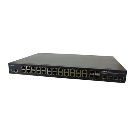
The Force10 Networks S2410 is a Layer 2 switch that is available in two models — the S2410CP and the
S2410P. The primary difference is that the S2410P contains 24 built-in 10-gigabit Ethernet (10G) XFP
ports, while the S2410CP contains 20 built-in 10G BaseCX4 ports and four 10G XFP ports.
Figure 1 The S2410CP (Front View)
Figure 2 The S2410 (Rear View)
Chapter 1 The S2410 System
10/100 Ethernet Management Port
Status LEDs
Console Port
20 XFP Ports (S2410P)
20 CX4 Ports (S2410CP) or
4 XFP Ports
Label
(Assembly and Serial #)
070-00285-00-1
10/100 Ethernet Management Port
Status LEDs
Console Port
20 XFP Ports (S2410P)
20 CX4 Ports (S2410CP) or
4 XFP Ports
Label
(Assembly and Serial #)
070-00285-00-1
1
2
3
4
5
6
7
8
9
10
11
12
13
14
15
16
17
18
19
20
21
22
23
24
S2410-01-10GE-24CP
10/100
Console
Ethernet
Alarm
PSU-A
PSU-B
L
A
L
A
L
A
L
A
L
A
L
AL
A
L
AL
A
L
AL
A
L
AL
A
L
AL
A
L
AL
A
L
AL
A
L
AL
A
L
AL
A
L
A
CLASS 1 LASER PRODUCT
LASERPRODUKT DER KLASSE1
Catalog #
System
Serial #
Serial #
Assy
Assy
fn00158s241
0
Dual AC Power Receptacles
Vents

8The S2410 System
Required Equipment
The following items are necessary to install the S2410 system:
• Two grounded AC power sources
• At least one cable (included) to connect the power source to the S2410 AC power supply
• Brackets and screws (included) for front-mounted rack installation (#2 Phillips screwdriver required
but not included)
• Console port: Rollover cable (RJ-45 connector) and terminal adapter (DB-9 to RJ-45) (supplied) (For
pinout and terminal settings, see Accessing the Console Port on page 23.)
Features
• 24 line-rate 10 GbE ports (See Ports for details.)
• CPU and switch processor
• Flash memory
• Standard 1U chassis height by 19-inch rack-mountable width
• Several rack attachment options; front-mount brackets standard
• Seven built-in fans on the left side (see Fans and Airflow on page 12)
• Load-sharing redundant internal AC power supplies
• Up to 16000 MAC address entries supported with hardware assisted aging
• Supports 9000 jumbo frames
• Back-pressure support at half-duplex, IEEE 802.3x flow control at full duplex
• Extensive LEDs for per-port and system statuses (see LED Displays on page 9)
Ports
S2410CP:
• 20 fixed 10GbE BaseCX4 ports
• 4 ports for optional 10G XFP transceivers (needs XFP optics)
• 1 RJ-45 console port with RS-232 signaling
• 1 RJ-45 10/100 dedicated Ethernet Management port (labeled 10/100 Ethernet)
S2410P:
• 24 fixed 10GbE XFP ports (needs XFP optics)
• 1 RJ-45 console port with RS-232 signaling
• 1 RJ-45 dedicated Ethernet Management port (labeled 10/100 Ethernet)
For details on using ports (console, CX4, Ethernet Management, and XFP), see Chapter 4, Accessing
Ports, on page 23.

Installing the S2410 System 9
System Status
S2410 status data can be derived in several ways, including physical LED displays, discussed next, along
with boot menu options, CLI show commands, SNMP traps, and the SFTOS Web User Interface. For
details on those options, see the S2410 Quick Reference, the SFTOS Command Reference (SFTOS 2.4),
and the SFTOS Configuration Guide (SFTOS 2.4).
LED Displays
As shown in Figure 1 on page 7, the S2410 contains a set of system status indicators on the right side of the
front panel. Those indicators are explained in Table 2. Also, each port has status indicators, which are
described in Table 3 on page 10.
The following table describes the LED status indicators on the left side of the front panel.
Table 2 Status Panel LED Display
LED Label LED Color Description
System Off
Green Blinking
Green
Red
Unit is powered off.
Unit is booting up (blinking rate is 1 Hz).
Unit is operational
Error during boot
Alarm Off
Amber
Red
No alarm
Minor alarm: Fan or temperature is outside acceptable range
Major alarm
PSU A
and
PSU B
Off
Green
Red
PSU not present
PSU present and OK
Red could mean that the PSU is present but failed, or that one power cord
that used to be connected is now disconnected.
The syslog message indicates “AC Power removed or fault detected.”

10 The S2410 System
Table 3 Port LED Displays
Feature Description
10G Ports Link LED (upper left side of each port except 1 and 2):
Green — Link up on this port
Off — No Link detected at this port
Activity LED (lower left side of each port except 1 and 2)
Blinking Green — Activity, transmitting or receiving packet at this port.
Off — No activity
Ethernet Management Port
(labeled 10/100 Ethernet)
(commonly called the service
port)
Link LED (lower left side of port):
Green — 100BaseT Link up on this port (1000 is not guaranteed.)
Off — No Link detected at this port
Activity LED (lower right side of port)
Blinking Green — Activity, transmitting or receiving packet at this port.
Off — No activity

Installing the S2410 System 11
This chapter describes requirements and site setup procedures for your S2410 system.
This chapter covers the following topics:
•Site Selection
•Cabinet Placement on page 12
•Rack Mounting on page 12
•Fans and Airflow on page 12
•Power on page 13
•Storing Components on page 13
•Tools Required on page 13
For detailed S2410 specifications, refer to Chapter 5, S2410 Specifications, on page 27.
Site Selection
Make sure that the area where you install your S2410 chassis meets the following safety requirements:
• Near an adequate power source. Connect the system to the appropriate branch circuit protection as
defined by your local electrical codes. Ideally, you connect each power supply to a separate circuit.
• Environmental temperature between 32° – 122°F (0° – 40°C).
• Relative humidity that does not exceed 90% non-condensing.
• In a dry, clean, well-ventilated and temperature-controlled room, away from heat sources such as hot
air vents or direct sunlight.
• Away from sources of severe electromagnetic noise.
• Positioned in a rack, cabinet, or on a desktop with adequate space in the front, rear, and sides of the
unit for proper ventilation, and access (see below).
Chapter 2 Site Preparation
Note: Install the S2410 into a rack or cabinet before installing any optional components.

12 Site Preparation
Cabinet Placement
The cabinet must meet the following criteria:
• Minimum cabinet size and airflow are according to the EIA standard.
• Minimum of 5 inches (12.7 cm) between the side intake and exhaust vents and the cabinet wall.
Rack Mounting
Ensure that your equipment rack is earth ground. The equipment rack must be grounded to the same
ground point used by the power service in your area. The ground path must be permanent.
Fans and Airflow
Ventilation is primarily side-to-side (some vents in back), with seven fans on the left side of the switch that
operate at a constant speed. For proper ventilation, position the chassis in an equipment rack (or cabinet)
with a minimum of five inches (12.7 cm) of clearance around the side intake and exhaust vents. When two
S-Series systems are installed side by side, position the two chassis at least 5 inches (12.7 cm) apart to
permit proper airflow. The acceptable ambient temperature ranges are listed in Environmental Parameters
on page 27.
As listed in Table 2, “Status Panel LED Display,” on page 9, the front panel of the S2410 has an Alarm
LED that includes alarms for fan problems and out-of-range temperatures. The LED is amber when the
temperature or components are outside expected parameters, red in a major alarm.
SFTOS logs a temperature warning message when a temperature of 77 degrees C is reached, and logs
another message when the temperature returns to normal. The Command Line Interface (CLI) also reports
an alarm.
Use the show logging buffered command to display the system log messages, and the show logging
command for event log messages,. For details, see the Syslog chapters of the SFTOS Command Reference
or SFTOS Configuration Guide.
Fan replacement is not offered as an option in the field.

Installing the S2410 System 13
Power
Both S2410 models (S2410CP and S2410P) provide built-in dual AC power supplies. Ideally, the power
sources would be on separate circuits. While only one power supply is needed for the unit to operate, if
both power supplies are connected, the power supplies act as redundant backups and do some load sharing,
although the sharing is not necessarily equal.
There are no DC power or backup power options.
Storing Components
If you do not install your system and components immediately, Force10 Networks recommends that you
properly store the S2410 and all optional components until you are ready to install them.
Follow these storage guidelines:
• Storage temperature should remain constant ranging from -4° to 158° F (-20°C to 70° C).
• Storage humidity range should be between 10 to 95% relative humidity, non-condensing
• Store on a dry surface or floor, away from direct sunlight, heat, and air conditioning ducts.
• Store in a dust-free environment.
Tools Required
S-Series switches are shipped fully assembled, encased in foam. A utility knife is useful for cutting the
packing tape, and a Philips #2 screwdriver is required for attaching rack screws, and is also used for making
some attachments, including DC cables and rear cover plates. Wear an anti-static guard, as noted above.
Caution: The power supply cord is used as the main disconnect device; ensure that the
socket-outlet is located/installed near the equipment and is easily accessible.
Warning: Electrostatic discharge (ESD) damage can occur when components are mishandled.
Always wear an ESD-preventive wrist or heel ground strap when handling the S2410 and its
accessories. After you remove the original packaging, place the S2410 and its components on an
antistatic surface.

14 Site Preparation

Installing the S2410 System 15
S2410 systems have no stacking or other optional modules, so, to install the S2410 system, you can simply
install the system on a tabletop, in a rack, or in a cabinet, turn it on, and then connect ports. The following
options are discussed in this chapter:
•Tabletop Installation
•Rack or Cabinet Installation
•Supplying Power on page 22
Then see Where Do I Go from Here?
Tabletop Installation
The S2410 can be positioned on a tabletop. Keep the following in mind when using a tabletop:
• Ensure that your tabletop is stable and can handle the weight of the S2410 (see Chassis Physical
Design on page 27).
• Position the S2410 so that there is proper side ventilation (see Fans and Airflow on page 12).
• Position the S2410 so that there is easy access to the rear power inlets, and an unobstructed path
between power inlets and outlets.
Rack or Cabinet Installation
The S2410 provides three rack-mounting methods:
•Two-Post Rack Mounting on page 17
•Four-Post Rack-mounting with Threaded Rails on page 18
•Four-Post Rack-mounting with Cage Nuts on page 20
Chapter 3 Installing the S2410
Warning: As with all electrical devices of this type, take all the necessary safety precautions to
prevent injury when installing this system. Electrostatic discharge (ESD) damage can occur if
components are mishandled. Always wear an ESD-preventive wrist or heel ground strap when
handling the S2410 and its components.

16 Installing the S2410
Attaching the Rack Ears
The S2410 is shipped with two universal front-mounting brackets (rack ears), which are contained in a bag
with 3 philips screws for each rack ear. The rack ears must first be attached to the front corners of the
switch before performing any of the rack-mounting procedures presented here. .
The lower right corner of Figure 3 shows the positioning of the rack ears and screws. Note that the rack
ears supplied with the S2410 have a hole in the middle to accommodate the vent in the S2410.
Figure 3 Attaching Rack Ears to Switch
Warning: Use only the supplied screws for attaching the rack ears. Longer screws might compromise
the electronics. Shorter or weaker screws might not adequately support the S2410.
752-00350-00

Installing the S2410 System 17
Two-Post Rack Mounting
Ensure that there is adequate clearance surrounding the rack to permit access and airflow (see Chapter 2,
Site Preparation, on page 11).
If you are installing two S2410 systems side-by-side, position the two S2410 chassis at least 5 inches (12.7
cm) apart to permit proper airflow.
Position the S2410 chassis in the rack (attach the rack ears first, using only the supplied screws; see
Attaching the Rack Ears on page 16). Secure the chassis with two screws through each bracket (rack ear)
and onto the front rack post, as shown in Figure 4. .
Figure 4 S2410 Two-post (Front-mounted) Rack-mounting
fn00147as241
0

18 Installing the S2410
Four-Post Rack-mounting with Threaded Rails
Ensure that there is adequate clearance surrounding the cabinet or rack to permit access and airflow. If you
are installing two S2410 systems side-by-side, position the two S2410 chassis at least 5 inches (12.7 cm)
apart to permit proper airflow.
Attach the rack ears first, using only the supplied screws (see Attaching the Rack Ears on page 16), and
then follow the steps below to install the S2410 chassis into a four-post 19-inch equipment rack, using the
attached front mounting brackets and the optional adjustable rear-mounting brackets.
Step Task
1. Align the three screw holes of the adjustable rear mounting bracket with the three holes in the S2410
chassis, and secure the mounting bracket with three screws.
752-00313-00F2(4-post1)

Installing the S2410 System 19
2. Insert the S2410 into the rack, and secure the chassis to the front post with two screws. Then secure
the chassis to the rear posts with two screws.
3. Set the adjustable rear mounting bracket to the length (one of three lengths) for your bracket. Secure
the length with the four screws.
Figure 5 Four-post Rack-mounting with Adjustable Rear-mounting Brackets
Step Task
fn00147s2410

20 Installing the S2410
Four-Post Rack-mounting with Cage Nuts
Ensure that there is adequate clearance surrounding the cabinet or rack to permit access and airflow. If you
are installing two S2410 systems side-by-side, position them at least 5 inches (12.7 cm) apart.
Attach the rack ears first, using only the supplied screws (see Attaching the Rack Ears on page 16), and
then follow the steps below to install the S2410 chassis into a four-post rack mounting with cage nuts.
Step Task
1. Attach the two rear brackets to the side panels. Align the three holes in the bracket with the three
holes on the S2410 chassis, and secure the brackets to the chassis using the screws.
2. Align and secure the adjustable bracket onto the rear bracket.
3. Insert the S2410 chassis into the rear of the rack. Position and secure the chassis with two screws
into each front bracket flange and into the rack post.
fn00147f_s2410
Align brackets
Top View of Brackets
fn00147a_s2410
Other manuals for S2410
2
Table of contents
Other Force 10 Switch manuals
Force 10
Force 10 S25P User manual
Force 10
Force 10 S-Series User manual
Force 10
Force 10 S50 User manual

Force 10
Force 10 Traverse Series User manual

Force 10
Force 10 S50 User manual
Force 10
Force 10 S2410 User manual

Force 10
Force 10 E600i TeraScale User manual
Force 10
Force 10 C300 Assembly Instructions

Force 10
Force 10 S2410 Installation manual

Force 10
Force 10 Traverse 2000 Installation instructions
