manuals.online logo
Brands
  1. Home
  2. •
  3. Brands
  4. •
  5. ORiNG
  6. •
  7. Switch
  8. •
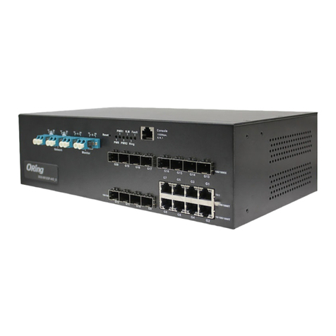
  9. ORiNG TPS-W9124GT-M12X-BP2 -24V-IP54 User manual

ORiNG TPS-W9124GT-M12X-BP2 -24V-IP54 User manual

FaultRingR.M.
Con sol e
Pow er 1
G1~ G4
1 BI_DA +
2 BI_DA -
3 BI_DB +
4 BI_DB -
6
5
7
3
2
18
4
5 BI_DD +
6 BI_DD -
7 BI_DC -
8 BI_DC +
Res et
P1 G1
P2 G2
P3 G3
P4 G4
LNK/ACT
Speed
LNK/ACT
Speed
LNK/ACT
Speed
LNK/ACT
Speed
LNK/ACT
Speed
LNK/ACT
Speed
LNK/ACT
Speed
LNK/ACT
Speed
Power
Failu re
Bypas s
Power
Failu re
Bypas s
Pow er 2
V1+
V1-
N.C
V2+
V2-
N.C
Tx+ Rx+
Tx-Rx-
P1~ P12
P9
P10
P11
P12
P5
P6
P7
P8
GND
N.C
N.C
PWR1 PW R2
RS-23 2, 11520 0bps, 8 , N, 1
N.C.
RXD
GND
TXD
N.C.
TPS- W912 4GT-M 12X- BP2- 24V
PoE
PoE
PoE
PoE
PoE
PoE
PoE
PoE
Quick Installation Guide
Version 1.0
Quick Installation Guide
Introduction
PRINTED ON RECYCLED PAPER
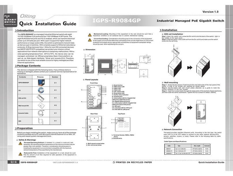
ORing's Transporter series managed PoE Ethernet switches are designed
TM
for industrial waterproof applications, such as rolling stock, vehicle, and
railway applications. is managedTPS-W9124GT-M12X-BP2-24V-IP54
Redundant Ring Ethernet switch with 12x10/100Base-T(X) P.S.E. and
4x10/100/1000Base-T(X) ports which is specifically designed for the
toughest and fully compliant with EN50155 requirement. The switch support
Ethernet Redundancy protocol, O-Ring (recovery time < 10/30ms over 250
units of connection), O-Chain, MRP*NOTE and MSTP/RSTP/STP (IEEE
802.1s/w/D) can protect your mission-critical applications from network
interruptions or temporary malfunctions with its fast recovery technology.
TPS-W9124GT-M12X-BP2-24V-IP54 also support Power over Ethernet, a
system to transmit electrical power up to 30 watts, along with data, to remote
devices over standard twisted-pair cable in an Ethernet network. Each TPS-
W9124GT-M12X-BP2-24V-IP54 switch has 12x10/100Base-T(X) P.S.E.
(Power Sourcing Equipment) ports. P.S.E. is a device (switch or hub for
instance) that will provide power in a PoE connection. TPS-W9124GT-
M12X-BP2-24V-IP54 includes 2 sets of bypass ports that protect the network
from failures and Network maintenance by ensuring network integrity during
power loss. And support wide operating temperature from -40 C to 75 C.
o o
TPS-W9124GT-M12X-BP2-24V-IP54 can also be managed centralized and
convenient by Open-Vision, Except the Web-based interface, Telnet and
console (CLI) configuration. Therefore, the switch is one of the most reliable
choices for EN50155 waterproof highly-managed Ethernet application.
Package Contents
Wall-mount
Contents
CD
TPS-W9124GT-M12X-BP2
-24V-IP54
Pictures Number
1
1
1
Wall-mount Kit 4
Dimension
Q I G 1907-200-JW9124X541-FX010
TPS-W9124GT-M12X-BP2-24V-IP54
Preparation
Before you begin installing the device, make sure you have all of the package
contents available and a PC with Microsoft Internet Explorer 6.0 or later, for
using web-based system management tools.
Panel Layouts
Top View
Installation
QIG
1. Wall-mount screw holes
TPS-W9124GT-M12X-BP2
-24V-IP54
The device is shipped with the following items. If any of these items is missing
or damaged, please contact your customer service representative for
assistance.
1
EN50155 Industrial IP-54 managed
PoE Ethernet switch
*NOTE: This function is available by request only
Unit =mm (Tolerance ±0.5mm)
Follow the steps below to install the device to the wall.
Step 1: Screw the Four pieces of wall-mount kits onto bottom side of the switch. A total of four
screws are required.
Step 2: Hold the device upright against the wall.
Step 3: Insert four screws through the holes at the top of the plate and fasten the screws to
the wall.
1
Instead of screwing the screws in all the
way, it is advised to leave a space of about
2mm to allow room for sliding the switch
between the wall and the screws.
For pin assignments of power and console port, please refer to the following tables.
Wiring
Grounding
Grounding and wire routing help limit the effects of noise due to electromagnetic interference
(EMI). Run the ground connection from the grounding pin on the power connector to the grounding
surface prior to connecting devices.
Power port pinouts
The device supports two sets of power supply and uses the M12 S-coded
4-pin male connector on the front panel for power inputs.
Step 1: Insert a power cable to the power connector on the device.
Step 2: Rotate the outer ring of the cable connector until a snug fit is
achieved. Make sure the connection is tight.
Network Connection
When installed outdoors, make sure the connectors on the panel are facing down
to prevent water intrusion.
Do not remove the water-proof casing, and do not touch or move the device
when the antennas are transmitting or receiving signals.
Safety & Warnings
4
5
2
3
6
7
98
11
10
13
12
1. Reset button
2. Power LED
3. R.M. status LED
4. Ring status LED
5. Fault LED
6. Console port
7. Power connector
8. PoE Fast Ethernet port
9. Gigabit Ethernet port with bypass
10. Link/ACT LED for PoE Ethernet port
11. Speed LED for PoE Ethernet port
12. Link/ACT LED for Gigabit Ethernet port
13. Speed LED for Gigabit Ethernet port
14. Ground wire
15. PoE status LED for PoE Ethernet port
Bottom View
1
14
RS-232, 115200bp s, 8, N , 1
N.C.
RXD
GND
TXD
N.C.
V+
V-
N.C
N.C
Console port pinouts
The switch has one RS-232 (M12 5pin) console port,
located on the front panel. Use a M12-to-DB9
console cable to connect the console port to your
PC's COM port.
The switch has twelve 10/100Base-T(X) and four 10/100/1000Base-T(X) Ethernet ports in the form
of M12 connector. Depending on the link type, the switch uses CAT 3, 4, 5,5e UTP cables to
connect to network devices (PCs, servers, switches, routers, or hubs). Please refer to the
following table for cable specifications.
Cable
Type
Max. Length
Connector
10BASE-T Cat. 3, 4, 5 100-ohm UTP 100 m (328 ft)
4-pin female M12
D-coding connector
100BASE-TX Cat. 5 100-ohm UTP UTP 100 m (328 ft)
4-pin female M12
D-coding connector
1000BASE-T Cat. 5/Cat. 5e 100-ohm UTP UTP 100 m (328 ft)
8-pin female M12
X-coding connector
1
Tx+
2
Rx+
Tx-
3
Rx-
4
10/100Base-T(X) P.S.E M12 port with D-Coding
Pin No. Description
#1 Tx+ with PoE Vout+
#2 Rx+ with PoE Vout-
#3 Tx- with PoE Vout+
#4 Rx- with PoE Vout-
For pin assignments of the M12 ports, please refer to the following tables.
4-Pin PoE Fast Ethernet Port Definition
S w i tc h
E N 5 0 1 5 5
I N D U S T R I A L
I P - 5 4
Faul tRingR.M.
Con sol e
Pow er 1
G1~ G4
1 BI_D A+
2 BI_D A-
3 BI_D B+
4 BI_D B-
6
5
7
3
2
18
4
5 BI_D D+
6 BI_D D-
7 BI_D C-
8 BI_D C+
Reset
P1 G1
P2 G2
P3 G3
P4 G4
LNK/ ACT
Spee d
LNK/ ACT
Spee d
LNK/ ACT
Spee d
LNK/ ACT
Spee d
LNK/ACT
Spee d
LNK/ACT
Spee d
LNK/ACT
Spee d
LNK/ACT
Spee d
Powe r
Fail ure
Bypa ss
Powe r
Fail ure
Bypa ss
Pow er 2
V1+
V1-
N.C
V2+
V2-
N.C
Tx+ Rx+
Tx-Rx-
P1~ P12
P9
P10
P11
P12
P5
P6
P7
P8
GND
N.C
N.C
PWR1 PW R2
RS-23 2, 11520 0bps, 8 , N, 1
N.C.
RXD
GND
TXD
N.C.
TPS- W91 24GT- M12X -BP 2-24 V
262 .00
90. 0
PoE
PoE
PoE
PoE
PoE
PoE
PoE
PoE
When installing the device, make sure to keep the radiating at a minimum distance of 20 cm
(7.9 inches) from all persons to minimize the potential for human contact during normal
operation.
Do not operate the device near unshielded blasting caps or in an otherwise explosive
environment unless the device has been modified for such use by qualified personnel.
15
Q I G Quick Installation Guide
Quick Installation Guide
Q I G
Specifications
Resetting
To restore the device configurations back to the factory defaults, press the button for 5Reset
seconds. Once the power indicator starts to flash, release the button. The device will then reboot
and return to factory defaults.
PRINTED ON RECYCLED PAPER
ORing Industrial Networking Corp.
Copyright© 2021 ORing
All rights reserved.
TEL: +886-2-2218-1066
FAX: +886-2-2218-1014
Website: www.oringnet.com
E-mail: support@oringnet.com
Configurations
6
5
7
3
2
1
8
4
After installing the and connecting cables, he green power LEDswitch t
should turn on. Please refer to the following tablet for LED indication.
3. After logging in, you should see the following screen. For more information on
configurations, please refer to the user manual. For information on operating the device
using ORing’s Open-Vision management utility, please go to ORing website.
Version 1.0
10/100/1000Base-T(X) M12 port with X-Coding
Pin No. Description
#1 BI_DA+
#2 BI_DA-
#3 BI_DB+
#4 BI_DB-
#5 BI_DD+
#6 BI_DD-
#7 BI_DC-
#8 BI_DC+
8-Pin Gigabit Port Definition
LED
Color
Status
Description
PWR1 Green On DC power module 1 activated
PWR2 Green On DC power module 2 activated
R.M Green On Device operating in Ring Master mode
Ring Green
On Ring enabled
Blinking Ring structure is broken
Fault Amber On Errors occur (i.e. power failure or port malfunctioning)
10/100Base-T(X) P.S.E Ethernet ports
LNK/ACT Green On Port is linked
Blinking Transmitting data
PoE Green On Power supplied over Ethernet
Speed Amber On Port is running at 100Mbps
Off Port is running at 10Mbps
10/100/1000Base-T(X) Ethernet ports
LNK/ACT Green On Port is linked
Blinking Transmitting data
Speed
Green On Port is running at 1000Mbps
Amber On Port is running at 100Mbps
Green/Amber Off Port is running at 10Mbps
1. Launch the Internet Explorer and type in IP address of the device. The default static
IP address is 192.168.10.1
Follow the steps below to log in and access the system:
2. Log in with default user name and password (both are ).admin
Power
Inpu t Power
Power Consumption(Typ.)
Du a l 2 4VDC (power rating: 16.8 ~ 3 0VDC) on dual 4- p i n male S-codi n g c onnector
22 Watts ( p o wer consump t i on of P.S.E. is n o t i ncluded)
Reset Function
Reset Button < 5 sec: Syste m r e boot, > 5 sec: Factory d e fault
Ove r l oad Current Protection
Reverse Pol a r i ty Protection
Pre s ent
Pre s ent
ORing Switch Model
10/1 0 0 B a s e-T(X) with P.S.E
Ports in M12 Auto MDI/MDIX 12 (4-pin female D-coding)
Physical Ports
Technology
Ethe r n e t S tandards
IEEE 8 0 2 . 3 f or 10Base-T
IEEE 8 0 2 . 3 u for 100Base-TX
IEEE 8 0 2 . 3 ab for 1000Base-T
IEEE 8 0 2 . 3 x for Flow control
IEEE 8 0 2 . 3 ad for LACP (Link Aggregatio n C o n t r ol Protocol)
IEEE 8 0 2 . 1 p for COS (Class of Service)
IEEE 8 0 2 . 1 Q for VLAN Tag g i ng
IEEE 8 0 2 . 1 w for RSTP (Rapid Span n i n g Tree Protocol)
IEEE 8 0 2 . 1 s for MSTP (Multiple Spannin g Tree Protocol)
IEEE 8 0 2 . 1 x for Authentication
IEEE 8 0 2 . 1 AB for LLDP (Link Laye r D i s c overy Protocol)
IEEE 8 0 2 . 3 at PoE specificat i o n ( u p to 30 Wa t t s p er port for P.S.E.)
IEEE 8 0 2 . 3 af PoE specifica t i o n ( u p to 15.4 Wa t ts per port for P.S.E.)
8k
MAC Table
8
Prio r i ty Queues
TPS-W9124GT-M12X-BP2-24V-IP54
10/1 0 0 / 1 000Base-T(X) ports
in M1 2 4 (8-pin female X-coding with 2xbypass function included)
RS-2 3 2 S e r ial Console Port RS-232 in M12 connector (female A-coding). B a u d r a te setting: 115200bps, 8, N, 1
Stor e -and-Forwa r d
Proc e s s i ng
Sw i t c h Properties
Sw i t c hing latency: <7 µs
Sw i t c hing bandwidth: 10.4Gbps
Thro u g h p ut (packet per second): 7. 7 3 8 M pps@64Bytes packet
Max. N u m b e r of Avai l a b l e VLANs: 4095
IGMP m u l t i cast groups: 128 for each VLAN
Port rate limiting : U s e r D efine
Secu r i ty Features
Devi c e B i nding security feature
Enab l e / d isable ports, MAC based port se c u r i ty
Port based network access co n t r o l ( 802.1x)
VLAN ( 8 0 2 . 1Q) to segregate and secure ne t w o r k traffic
Radius centralize d p a s sword management
SNMP v 3 e n c rypted authentication an d a c c e s s security
Http s / SSH enhance network securit y
Soft w are Features
STP/ R S T P / MSTP (IEEE 802.1D/w/s)
Redundant Ring (O-Ring) wit h r e c overy time less than 10 / 3 0 m s over 250 units
. Fast Ethernet po r t s s u pports less 10ms milliseco n d s r e c overy timeNOT E 1
Giga b i t E t hernet ports supports less 30 m s m i lliseconds recover y t i m eNOT E 2 .
TOS/Diffserv supported
Qual i t y of Service (802.1p) for real - t i m e traffic
VLAN ( 8 0 2 . 1Q) with VLAN tagging and GVRP s u p p o r ted
IGMP S n o o p ing
IP-b a s e d b andwidth management
Appl i c a t ion-based QoS management
DOS/ D D O S a uto prevention
Port configurati o n , s t a tus, statistics, monitor i n g , s e curity
DHC P S e r ver/Client/Re l ay
SMTP C l i e n t
Modb u s TCP
Netw o r k Redundancy
O-Ri n g
O-Ch a i n
MRP* N O TE
MSTP ( R S T P /STP compatible)
4Mbi t s
Packet Buffer Size
Up to 9. 6 K B y t es
Jumb o F rame
Physical Charac teristic
Encl o s u r e I P-54
Dim e n s i o n (W x D x H) 28 0 ( W ) x 90 (D) x 182 (H) mm ( 1 1 .02 x 3.54 x 7.17 i n c h.)
Weight (g) 32 2 0 g
Environmental
-40 t o 8 5 C (- 40 to 185 F)
o o
Storage Tempe rature
5% t o 9 5 % Non-conden s i ng
Operating Humidity
Regulatory Appr ovals
EN 55 0 32, CISPR32, E N 6 1 000-3-2, EN 6 1 0 00-3-3, FCC Part 15 B class A
EMI
EN 55 0 35 (IEC/EN 610 0 0 -4-2 (ESD), I E C /EN 61000-4- 3 ( R S), IEC/EN 610 0 0-4-4 (EFT),
IEC / E N 61000-4-5 ( S u rge), IEC/EN 6 1 000-4-6 (CS) , I E C/EN 61000-4 - 8 (PFMF), IEC / E N 61000-4-11 ( D I P))
EMS
IEC 6 0068-2-27
Shoc k
IEC 6 0068-2-31
IEC 6 0068-2-6
Vibration
Free Fall
MTBF
15 4 , 712 hrs
EN 62 3 68-1 (LVD)
Safe t y
-40 t o 7 5 C (- 40 to 167 F)
o o
Operating Tem p e rature
*Note: This functi on is available b y request only.
CE EM C ( EN 55035, EN 550 3 2 ), FCC Par t 1 5 B, EN 50155( E N 5 0121-1, EN 50 1 2 1-3-2)
EMC
EN 50 1 55(IEC 61373 )
Othe r
Warranty
5 ye a rs
S w i tc h
E N 5 0 1 5 5
I N D U S T R I A L
I P - 6 7
Total PoE Out p u t Power <24 V DC: 60 Watts Max.
24 V D C: 90 Wa tts Max.≧
TPS-W9124GT-M12X-BP2-24V-IP54
TPS-W9124GT-M12X-BP2
-24V-IP54
EN50155 Industrial IP-54 managed
PoE Ethernet switch

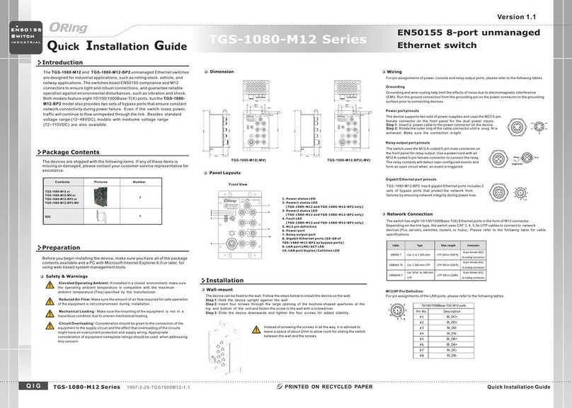
Other ORiNG Switch manuals

ORiNG RGS-7244GP User manual

ORiNG

ORiNG RGS-7244GP User manual

ORiNG IGS-1042GPA User manual

ORiNG

ORiNG IGS-1042GPA User manual

ORiNG IGS-1050A User manual

ORiNG

ORiNG IGS-1050A User manual

ORiNG TPS-3162GT-M12-BP1 User manual

ORiNG

ORiNG TPS-3162GT-M12-BP1 User manual

ORiNG TPS-3882GT-M12-BP1 User manual

ORiNG

ORiNG TPS-3882GT-M12-BP1 User manual

ORiNG RGS-R9004GP+ME-HV User manual

ORiNG

ORiNG RGS-R9004GP+ME-HV User manual

ORiNG IGS-9084GP-LA User manual

ORiNG

ORiNG IGS-9084GP-LA User manual

ORiNG RES-1242P User manual

ORiNG

ORiNG RES-1242P User manual

ORiNG RGS-R9244GP+ Series User manual

ORiNG

ORiNG RGS-R9244GP+ Series User manual

ORiNG IPS-1080A User manual

ORiNG

ORiNG IPS-1080A User manual

ORiNG IGS-3044GC User manual

ORiNG

ORiNG IGS-3044GC User manual

ORiNG IES-3162GC Series User manual

ORiNG

ORiNG IES-3162GC Series User manual

ORiNG IES-1041FX-MM-SC User manual

ORiNG

ORiNG IES-1041FX-MM-SC User manual

ORiNG IGPS-1080-24V User manual

ORiNG

ORiNG IGPS-1080-24V User manual

ORiNG IES-1050A User manual

ORiNG

ORiNG IES-1050A User manual

ORiNG IGS-1082GP User manual

ORiNG

ORiNG IGS-1082GP User manual

ORiNG IGS-9168GP series User manual

ORiNG

ORiNG IGS-9168GP series User manual

ORiNG IGS-9844GPFX Series User manual

ORiNG

ORiNG IGS-9844GPFX Series User manual

ORiNG IGPS-R9084GP User manual

ORiNG

ORiNG IGPS-R9084GP User manual

ORiNG IGPS-9084GP User manual

ORiNG

ORiNG IGPS-9084GP User manual

ORiNG IPS-1042FX-24V Series User manual

ORiNG

ORiNG IPS-1042FX-24V Series User manual

ORiNG CPS-3080-C Operating and maintenance instructions

ORiNG

ORiNG CPS-3080-C Operating and maintenance instructions

ORiNG DGS-9168GP-SS-AIO_S User manual

ORiNG

ORiNG DGS-9168GP-SS-AIO_S User manual

ORiNG TGS-1080-M12 Series User manual

ORiNG

ORiNG TGS-1080-M12 Series User manual

Popular Switch manuals by other brands

Alereon Confidential AL5612 user guide

Alereon Confidential

Alereon Confidential AL5612 user guide

Compaq 400338-001 user guide

Compaq

Compaq 400338-001 user guide

iBall Baton iB-LGDS18G user guide

iBall Baton

iBall Baton iB-LGDS18G user guide

EUCHNER CES-I-BR Series operating instructions

EUCHNER

EUCHNER CES-I-BR Series operating instructions

Elkron IT700-POE Complete manual

Elkron

Elkron IT700-POE Complete manual

SmartRoom SR-ZCSWLPW-S1311-01 user manual

SmartRoom

SmartRoom SR-ZCSWLPW-S1311-01 user manual

FSR DV-HSW4K-41AUD user manual

FSR

FSR DV-HSW4K-41AUD user manual

H3C S12500 Series manual

H3C

H3C S12500 Series manual

Advantech ADAM-6521 Series user manual

Advantech

Advantech ADAM-6521 Series user manual

Broadcom Brocade G630 Hardware installation guide

Broadcom

Broadcom Brocade G630 Hardware installation guide

FS S5860-48SC Hardware installation and maintenance guide

FS

FS S5860-48SC Hardware installation and maintenance guide

HP zl user guide

HP

HP zl user guide

Smartwares SH4-99751 Assembly, operating and safety instructions

Smartwares

Smartwares SH4-99751 Assembly, operating and safety instructions

Code TC-182 user manual

Code

Code TC-182 user manual

LEGRAND AM5659 quick start guide

LEGRAND

LEGRAND AM5659 quick start guide

Thinklogical TLX Series product manual

Thinklogical

Thinklogical TLX Series product manual

Meicheng CMLUX-88S Operation manual

Meicheng

Meicheng CMLUX-88S Operation manual

FSR SN-4100A Operation manual

FSR

FSR SN-4100A Operation manual

manuals.online logo
manuals.online logoBrands
  • About & Mission
  • Contact us
  • Privacy Policy
  • Terms and Conditions

Copyright 2025 Manuals.Online. All Rights Reserved.