Force America ONE SSC5100ex Instruction manual

FORCE America ONETM
Quick Start Manual


FORCE America ONETM Quick Start Manual
Welcome and Table of Contents
i
Welcome
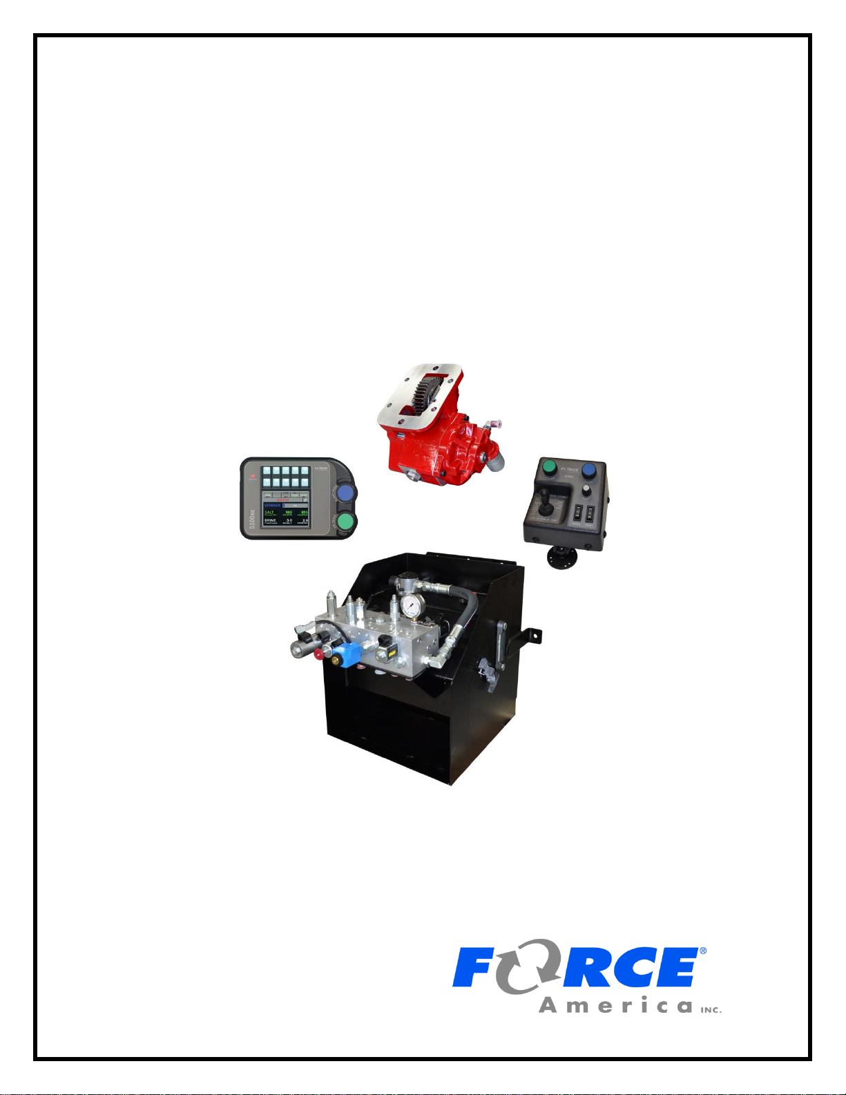
Congratulations on your purchase of a FORCE America ONETM joystick and spreader control.
This manual is designed to provide you with the basic information necessary to get your new
system up and running. For advanced operation and calibration features related to the
SSC5100ex Spreader Control please consult M0118 SSC5100ex Operation Manual or M0119
SSC5100ex Calibration Manual.
Table of Contents
Welcome ...........................................................................................................i
Table of Contents.............................................................................................i
Hardware..........................................................................................................1
FORCE America ONETM System Operation...................................................2
Powering up the SSC5100ex ............................................................................................... 2
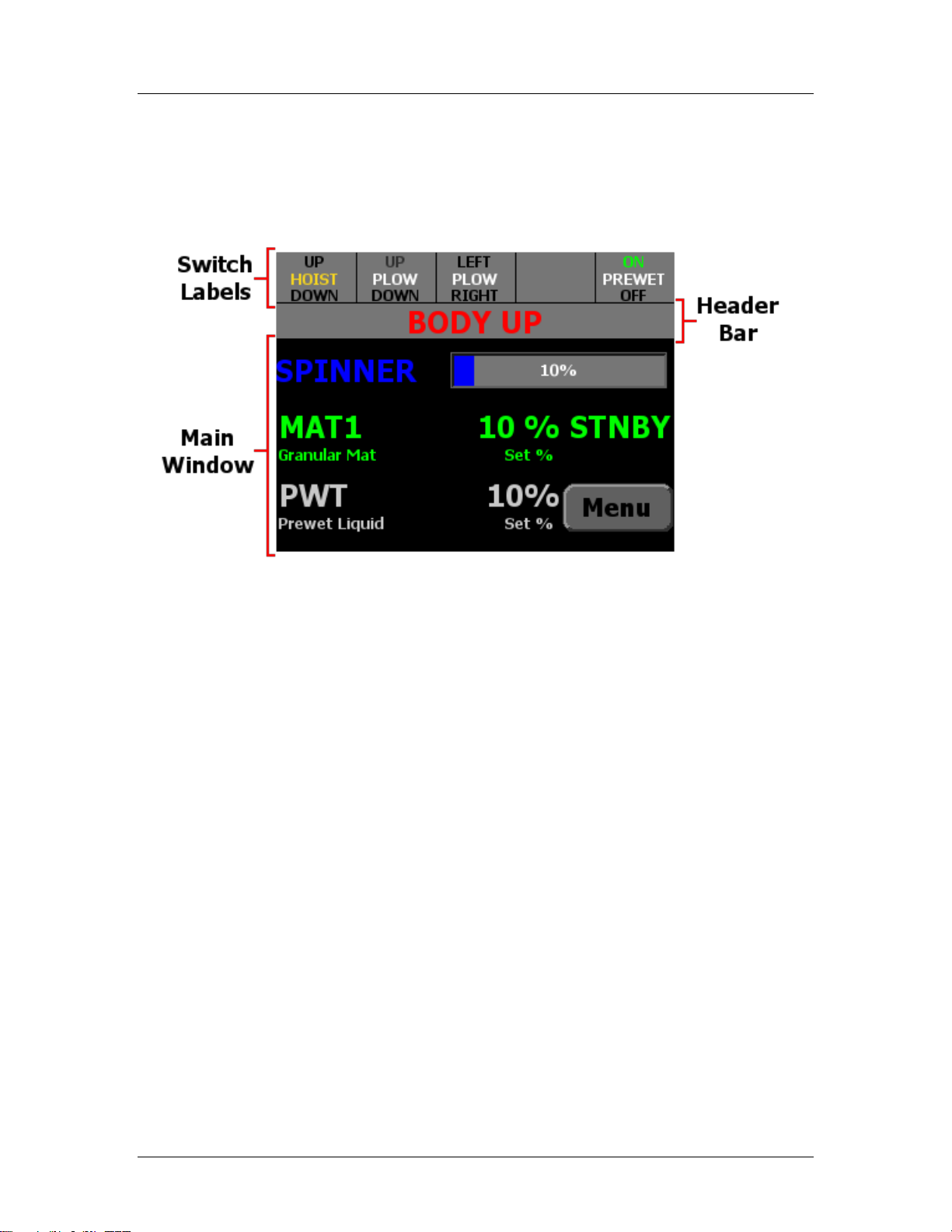
The Operation Screen........................................................................................................... 3
Remote Controls Operation............................................................................................... 10
FORCE America ONETM System Calibration...............................................11
Entering the Calibration Menu........................................................................................... 11
Hoist/Plow............................................................................................................................ 12
FORCE America Contact Information..........................................................14


FORCE America ONETM Quick Start Manual
Hardware
1
Hardware
The SSC5100ex is a self-contained spreader system. It has two rotary adjustment knobs, five
pairs of “switches” that act as pushbuttons for SSC5100ex functions, and an interlock “switch” on
the back of the controller. The functions that they control change depending on what options are
enabled. See Switch Labels on page 4. The left side of the SSC5100ex has a single USB port,
which can be used to import and export calibration files or upgrade the firmware.
Figure 1: The SSC5100ex
The remote controls provides the operator with three rotary adjustment knobs, inputs for remote
activation of blast and standby and control of hoist and plow operations using the attached
joystick.
Figure 2: Remote Controls

FORCE America ONETM Quick Start Manual
Power Up
2
FORCE America ONETM System Operation
The following information describes the basic features of the FORCE America ONETM system.
For details on more advanced operation of the spreader control please consult M0018
SSC5100ex Operation Manual.
Powering up the SSC5100ex
Upon applying 12V DC dashkey power to the SSC5100ex, it will display the Screen Power
Switch.
The Screen Power Switch
The Screen Power Switch is a safety feature of the SSC5100ex, it will prevent the system from
running spreader related outputs until the Continue button is pressed. When the Continue button
is pressed, it will display the Operation Screen.
Figure 3: Screen Power Switch

FORCE America ONETM Quick Start Manual
The Operation Screen
3
The Operation Screen
The Operation Screen is the main screen of the SSC5100ex, and provides controls for all of the
system functions as well as access to the menus.
The operation screen is divided into three distinct parts:
Figure 4: SSC5100ex Operation Screen

FORCE America ONETM Quick Start Manual
Switch Labels
4
Switch Labels
The 5 Switch Labels always run across the very top of the screen. Each label corresponds to the
switch directly above it. Active switch functions are indicated with a green color. If a switch is
currently not used the label is left blank. The switch label will appear red if the operator selected
the Disable option on the stuck switch error condition at startup. When in this state the affected
function will not be able to be activated.
Figure 5: Switch Labels
Switch
Function
Availability Requires
Momentarily activates the Hoist, running it at
max duty cycle until the switch or interlock is
released.
Pressing both the top switch and the interlock
(integrated into the back of the controller) at
the same time will move the hoist up.
Pressing both the bottom switch and the
interlock will move it down.
The Hoist & Plow option in
calibration must be set to
Hoist or Hoist & Plow.
Momentarily activates the Plow, running it at
max duty cycle until the switch is released.
The interlock switch is not required to run
these functions.
Pressing the top switch will move the plow up
and the bottom switch will move it down.
The Hoist & Plow option in
calibration must be set to
Plow or Hoist & Plow.
Momentarily activates the Plow, running it at
max duty cycle until the switch is released.
The interlock switch is not required to run
these functions.
Pressing the top switch will move the plow left
and the bottom switch will move it right.
The Hoist & Plow option in
calibration must be set to
Plow or Hoist & Plow.
Activates or deactivates the prewet output.
Pressing the top switch will turn on Prewet
and the bottom switch will turn it off.
See page 7.
Prewet must be enabled in
Calibration.

FORCE America ONETM Quick Start Manual
Header Bar
5
Header Bar
Figure 6: Header Bar
The Header Bar always runs across the top of the screen just below the switch labels. It contains
a series of system status messages and the PreCiseTM MRM status icon (if Event Logging is set
to PreCise).
System Status Messages will be displayed in the center of the Header Bar. If two or more system
status messages are active, the messages will alternate between each other at a rate of one
message every two seconds. In Figure 6 above, a Body Up condition has occurred, showing the
Body Up system status message in the header bar.
For more information on error conditions, see
M0018 SSC5100ex Operation Manual.

FORCE America ONETM Quick Start Manual
Main Window
6
Main Window
Figure 7: Main Window
The Main Window displays important information about the materials the system is spreading.
The blue spinner row contains information about your spinners set rate. The spinner row will only
appear when applying granular materials and adjusted using the blue knob.
The green row contains information about your primary material, and its set rate. This row is
always visible and adjusted using the green knob.
The white prewet row contains information about your prewet material and its set rate. The
prewet row will only appear when applying granular materials and Prewet is enabled in
Calibration. It is white when Prewet is activated and gray when Prewet is not activated.

FORCE America ONETM Quick Start Manual
Applying Material
7
Applying Material
When your FORCE America ONETM system arrives from the factory it will be ready to apply
granular material in manual mode. When the system starts up, it will be in Standby, as shown in
Figure 7. Standby deactivates all outputs.
Each rotary adjustment knob on the Spreader Control / Operator Interface performs a different
function when applying material. See the table below.
Input
Input
Function
Green On /
Standby Knob
Twist Left
Decrease the auger set rate.
Twist Right
Increase the auger set rate.
Pushbutton
Place the system in standby.
Remove the system from standby.
Blue Blast
Knob
Twist Left
Decrease the spinner set rate.
Twist Right
Increase the spinner set rate.
Pushbutton
Blast granular material.
Cancel Blast.
To spread granular material in manual mode:
STEP 1: Twist the On / Standby knob to adjust your granular output percentage.
STEP 2: Twist the Blast knob to adjust your spinner set rate.
STEP 3: Press the On / Standby knob to remove the spreader control from standby.
Granular material will spread regardless of whether the vehicle is moving or not.
STEP 4: Press the On / Standby knob to place the spreader control back in standby and
stop the outputs.
To spread granular and prewet material in manual mode:
STEP 1: Press the top half of the switch labeled “Prewet” above the screen to enable
prewet liquid application. The switch’s ON text will turn green when activated.
STEP 2: Twist the On / Standby knob to adjust your granular output percentage.
STEP 3: Twist the Blast knob to adjust your spinner set rate.
STEP 4: Press the button labeled Menu in the lower right-hand corner of the screen to
enter the Main menu.
STEP 5: Press the button labeled Material to enter the Material menu.
STEP 6: Press the button labeled Prewet Rate to access the prewet set rate.
STEP 7: Press the left and right arrow buttons to adjust your prewet output percentage.
When used with the optional remotes the gray knob can be twisted left and right
to decrease and increase the prewet output percentage.
STEP 8: Press the Ok button to save the setting and return to the Material menu.
To reduce the risk of death or injury, ensure
that all personnel are clear from moving
machinery before activating outputs.

FORCE America ONETM Quick Start Manual
Applying Material
8
STEP 9: Press the Back button to return to the Main menu.
STEP 10: Press the Back button to return to the operation screen.
STEP 11: Press the On / Standby knob to remove the spreader control from standby.
Granular and prewet material will spread regardless of whether the vehicle is
moving or not.
STEP 12: Press the On / Standby knob to place the spreader control back in standby and
stop the outputs.

FORCE America ONETM Calibration and Operation Manual
Blast
9
Blast
Blast is a spreader feature that runs the granular at 100% for 10 seconds.
When Blast is activated, the granular row will display the word “BLAST” instead of the material
name. See Figure 8.
Figure 8: Granular / Prewet Application Mode in Blast
To activate Blast:
STEP 1: Press the Blue Blast Knob on the Operator Interface. The system will blast for its
configured amount of time and return to normal operation. The Blast feature
works whether or not the system is in Standby or the vehicle is moving.
To deactivate Blast before it automatically shuts off:
STEP 1: While the system is Blasting, press the Blue Blast Knob on the Operator
Interface. The Blast feature will shut off and return to its previous operation
(spreading or standby).
To reduce the risk of death or injury, ensure
that all personnel are clear from moving
machinery before activating outputs.

FORCE America ONETM Quick Start Manual
Blast Operation
10
Remote Controls Operation
The Remote Controls when connected to the system provide an alternative method for activation
of the plow, hoist and spreader functions.
The green and blue knobs on the remote controls perform the same functions as the green and
blue knobs on the spreader control. In addition to those knobs the gray knob on the remote
controls provides the ability to adjust the prewet set rate. The table below describes the
operation of the knobs located on the remote control.
Input
Input
Function
Green On /
Standby Knob
Twist Left
Decrease the auger set rate.
Twist Right
Increase the auger set rate.
Pushbutton
Place the system in standby.
Remove the system from standby.
Blue Blast
Knob
Twist Left
Decrease the spinner set rate.
Twist Right
Increase the spinner set rate.
Pushbutton
Blast granular material.
Cancel Blast.
Gray Prewet
Knob
Twist Left
Decrease the prewet set rate.
Twist Right
Increase the prewet set rate.
The prewet system can be turned on and off using the rocker switch located below the gray knob,
this rocker switch performs the same operation as the far right switch on the spreader control.
The joystick on the remote controls performs the same functions as the first three switches on the
spreader control. The pushbutton on the joystick is used to switch the joystick output from plow
to hoist. When pressed the pushbutton will latch on the hoist operation until the joystick returns to
the center position where the state of the button will be evaluated to determine which function
should be operated. The table below describes the operation of the joystick located on the
remote controls.
Pushbutton Inactive
Pushbutton Active
Plow
Down
Hoist
Down
Plow
Left
Plow
Right
Plow
Up
Hoist
Up

FORCE America ONETM Quick Start Manual
Hoist/Plow Calibration
11
FORCE America ONETM System Calibration
The following information describes the calibration for the specific features related to the FORCE
America ONETM system. For details on the features that are not specific to the FORCE America
ONE System please consult the M0019 SSC5100ex Calibration Manual.
Entering the Calibration Menu
The Calibration menu is entered by pressing the Calib button in the Main Menu. Unlike the
Material Select, Unload, Data, and Version Menus, the Calibration Menu requires the entry of an
Access Code before it will appear. You can insert a USB supervisor key instead of entering the
access code to access the Calibration Menu.
To enter Calibration using Access Code:
1. While the system is in Standby, press the Menu button on the Operation Screen.
2. Press the Calibration menu button. The Access Code window will appear, as shown in
Figure 9.
Figure 9: The Access Code Window
3. Enter the access code using the up and down arrow buttons on screen. Use the left and
right arrows to move to a different digit. You may also tap a number cell to highlight it.
The factory default access code is 00000000.
When entering the Access Code, the buttons have the following functions:
Input
Function
Increase the highlighted digit by 1.
Decrease the highlighted digit by 1.
Highlight the previous digit.
Highlight the next digit.

FORCE America ONETM Quick Start Manual
Entering Calibration
12
Hoist/Plow
The Hoist/Plow menu allows you to configure settings related to the operation of the hoist and
plow.
Options
The Options item allows you to configure which of the hydraulic functions can be
activated using the unit. The default value is Hoist & Plow.
Option
Description
Hoist & Plow
The system will contain switch functions and outputs for the
hoist up, hoist down, plow up, plow down, plow left and plow
right hydraulic functions.
Hoist
The system will contain switch functions and outputs for the
hoist up, and hoist down hydraulic functions.
Plow
The system will contain switch functions and outputs for the
plow up, plow down, plow left and plow right hydraulic
functions.
Plow Float
The Plow Float menu item sets the operation of the Plow Down Float function. When
active the plow down float function will keep 12 V on the plow down output. The plow
down float function is deactivated by pressing the plow up switch. The default value is
Disabled.
Option
Description
Disabled
Plow float is not active.
Delayed
Plow float will activate when the plow down function is held for
3 seconds.
Enabled
Plow float will activate when the plow down function is
pressed.
Max DC
The Max DC submenu allows you to set the duty cycle that the switch related hydraulic
functions will operate at during standard operation.
Plow Up
The Plow Up menu item adjusts the duty cycle that the plow up output will
operate at during standard operation. The default value is 80%.
Plow Left
The Plow Left menu item adjusts the duty cycle that the plow left output will
operate at during standard operation. The default value is 50%.
Enter Access Code.
Return to the Main menu.

FORCE America ONETM Quick Start Manual
Hoist/Plow Calibration
13
Plow Right
The Plow Right menu item adjusts the duty cycle that the plow right output will
operate at during standard operation. The default value is 50%.
Hoist Up
The Hoist Up menu item adjusts the duty cycle that the hoist up output will
operate at during standard operation. The default value is 65%.
Limit Scheme
The Limit Scheme menu item selects the limit scheme profile that is used to limit the
output duty cycle when multiple hydraulic functions are requested to run at the same
time. The default limit scheme is low.
Option
Description
High
High limit operation is designed to be used with a 14 GPM
pump
Low
Low limit operation is designed to be used with a 9 GPM
pump.
Custom
Custom limit operation will allow for setting of the various limit
percentages to obtain the desired operation if the High and
Low limit scheme do not provide the desired operation.
Limit Percentages
The Limit Percentages submenu allows you to set the percentage of maximum range that
the switch related hydraulic function will operate at when in limit mode. Limit mode is
active whenever more than one of the following functions is active: Plow up, plow left,
plow right, hoist up, hoist down or auger. The values in this menu are only editable when
the Limit Scheme is set to Custom.
Plow Up
The Plow Up menu item adjusts the limit percentage for the plow up output. The
custom default value is 50%.
Plow Left
The Plow Left menu item adjusts the limit percentage for the plow left output. The
custom default value is 70%
Plow Right
The Plow Right menu item adjusts the limit percentage for the plow right output.
The custom default value is 70%
Hoist Up
The Hoist Up menu item adjusts the limit percentage for the hoist up output. The
custom default value is 50%
Hoist Down
The Hoist Down menu item adjusts the limit percentage for the hoist down
output. The custom default value is 50%
Auger
The Auger menu item adjusts the limit percentage for the auger output. When
the auger output is being limited the prewet output will be adjusted as well. The
custom default value is 62%

SSC5100ex Operation Manual
Contact Information
14
FORCE America Contact Information
Should you encounter problems with your FORCE America ONETM system that are not
documented in this manual, M0118 SSC5100ex Operation Manual or the M0119 SSC5100ex
Calibration Manual, please contact your local FORCE America Sales Representative for
assistance.
For company and product information, please contact FORCE America at:
Phone: 1-888-99FORCE (1-888-993-6723)
Website: http://www.forceamerica.com
E-mail: info@forceamerica.com


Document No: M0125-C
Released: 08/09/2016
Copyright © 2016 FORCE America Inc.
Table of contents
Other Force Control Unit manuals