94 SAFETY PRECAUTIONS
SYSTEM OPERATION
OWith monitor, telephones and distributor:
wDo not use excessive force when tightening the connector screws.
wInstall the equipments in a dry and protected place without risk of drip or water projections.
wAvoid to place it near to heating sources, in dusty locations or smoky enviroments.
wDo not block ventilation holes of the equipments so that air can circulate freely.
ODo always follow the enclosed information.
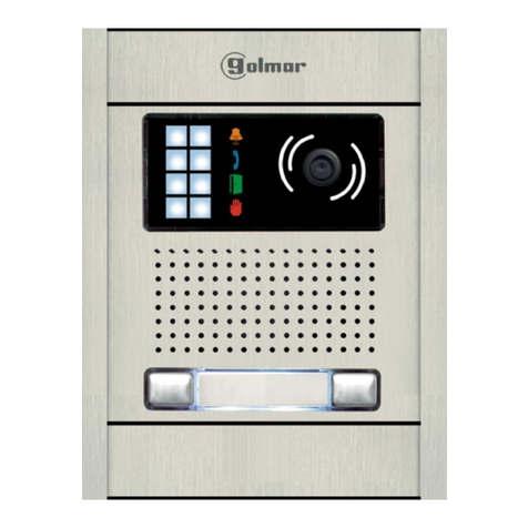
OTo make a call the visitor should press the push button corresponding to the apartment he wishes to
contact n acoustic tone will be heard confirming the call is in progress once the push button has
: a
been pressed At this moment the call will be received at theand the door panel led will turn on.
monitor (telephone) in the dwelling During the call the visitor can correct his call by pressing a push.
button corresponding to a different apartment, in which case the original call is cancelled.
OIn systems with several access doors, the other door panel(s) will be automatically disconnected: f a visitori
tries to call from other door panel an acoustic tone will be heard and the door panel led will be on
confirming the system is busy.
OThe call tone will be reproduced on the monitor during 3 seconds: after this time the picture will
appear on the master monitor without the visitor being aware of this To see the image on a slave
.
monitor pick up its handset, dissapering the image on the other monitor If the call is not answered in.
45 seconds, the system will be freeddoor panel led will turn off and the .
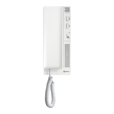
OTo establish communication pick up the monitor (telephone) handset, the door panel led will turn on.
OThe communication will last for one and a half minutes or until the handset is replaced Once the.
communication has finished the system will be freedthe door panel led will turn off and .
OTo open the door, press the door release push button during call or communication progresses with:
one press, the door release operates during 3 seconds and the led will also turn on for 3 seconds.
If there are SU-R5 Relay Units in the installation, two rapid presses open the door release of the second
'
door e door release of the SU-R5 Relay Unit selected (see TSU-R5 ML manual).' or th
Coming from previous page
SYSTEM CHARACTERISTICS
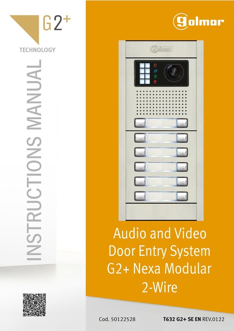
OVideo door entry system with simple installation specially-designed to replace 4+n audio door entry
systems. Installation is done through 5 common wires without independent call lines.
OBus Nexa Cn7: It allows the connection of illumination module (Nexa coded panel, see manual
TCode/CD Nexa).
OUp to 6 door (access) panels which do not need switching units.
OUp to 200 terminals (monitors and telephones) for installation without using converters.
OUp to 132 apartments with door panels of push buttons and up to 200 apartments with codedStadio/ Inox
panels (requires the use of the digital converter ) .CD-PLUS/R5 or Nexa code panel with Cn7 Bus Nexa
OVisual indications on the door panel for people with impaired hearing.
OAcoustic busy channel and call acknowledgement signals.
ODoor opening timed at 3 seconds.
OA.C. or D.C. lock release operated through a relay.
OWith telephones T- 30/R55 SU-R5:
wCompletely private conversation.
wOutput for connection to call repeater.
wUp to 1 additional monitor or telephone per apartment (installation of an additional monitor
requires a supplementary power supply in the landing, see page - )131 132 .
w' ' (requires the use of the SU-R5 elay nitR UFunction: opening the second door ).
wDoes NOT require batteries for operation.
OWith monitors Tekna R5 , in addition to the above featuresCol SU-R5 :
w.
Privacy on audio and video communications
w.'Video-Spy' function with the communication channel remaining free
wColour screen.
93
INTRODUCTION
INDEX
SAFETY PRECAUTIONS
First of all we would like to thank and congratulate you for the purchase of this product manufactured by
Golmar.
The commitment to reach the satisfaction of our customers is stated through the ISO-9001 certification
and for the manufacturing of products like this one.
Its advanced technology and exacting quality control will do that customers and users enjoy with the
legion of features this system offers. To obtain the maximum profit of these features and a properly wired
installation, we kindly recommend you to expend a few minutes of your time to read this manual.
OInstall or modify the equipment .without the power connected
OThe installation and handling of these equipments must be performed by .authorised personnel
OThe entire installation must be at least . away from any40 cm other installation.
OWith power supply:
wDo not use excessive force when tightening the connector screws.
wInstall the power supply in a dry and protected place without risk of drip or water projections.
wAvoid to place it near to heating sources, in dusty locations or smoky enviroments.
wDo not block ventilation holes of the unit so that air can circulate freely.
wTo avoid damage, the power supply has to be firmly fixed.
wTo avoid an electrical shock, neither remove the protection cover nor handle the connected wire
in the terminals.
Introduction ...........................................93
Index.....................................................93
Safety precautions .............................9 -93 4
Systems characteristics.............................94
System operation ....................................94
Definition ...........9& minimum requirements 5
Door panel description ............................96
Modules description....................................
Sound modules EL63 -R5/EL64 -R5 .....92 2 7
Push buttons module EL610D.................98
Door panel ................................................
Embedding box positioning ...................99
Embedding box installation ............9 -9 100
Assembly electronic modules ...............100
Hold the frame ...................................101
Push buttons connection............... -101 102
Push buttons coding............................102
Description Cn7 Bus Nexa connector ....103
Connection illumination module ..........103
Description illumination leds................104
Description visual indications...............104
Sound module configuration................105
Final adjustments .......10& close the frame 6
Place the nameplate labels ..................106
A & close the door panel 7ssembly ...........10
Power supply & lock release installation....108
Tekna R5 monitor ........................Col SU-R5
Description & function push buttons ......109
End of line resistor...............................110
Monitor connector description .............111
Monitor installation.............................112
Programming.....................................113
T- 30/R5 telephone ..........................5 SU-R5
Description ........1& function push button 14
Telephone installation .........................115
Programming.....................................116
Installation.................................................
Door panel.................................11 -117 8
Power supply and lock release ..............119
Reassignment of conductors ................120
Floor distribution.........................1 -121 22
Installation diagrams with D4L-R5 .................
Video sys. with d.c. lock release ............123
Video sys. with a.c. lock release/TF104 ..125
Installation diagrams with D4L-R5R ...............
Video sys. with d.c lock release .............127
Installation diagram Audio system ...........129
Optional connections ....................1 -131 35
Troubleshooting hints ............................136
Compliance.........................................139
Continue

