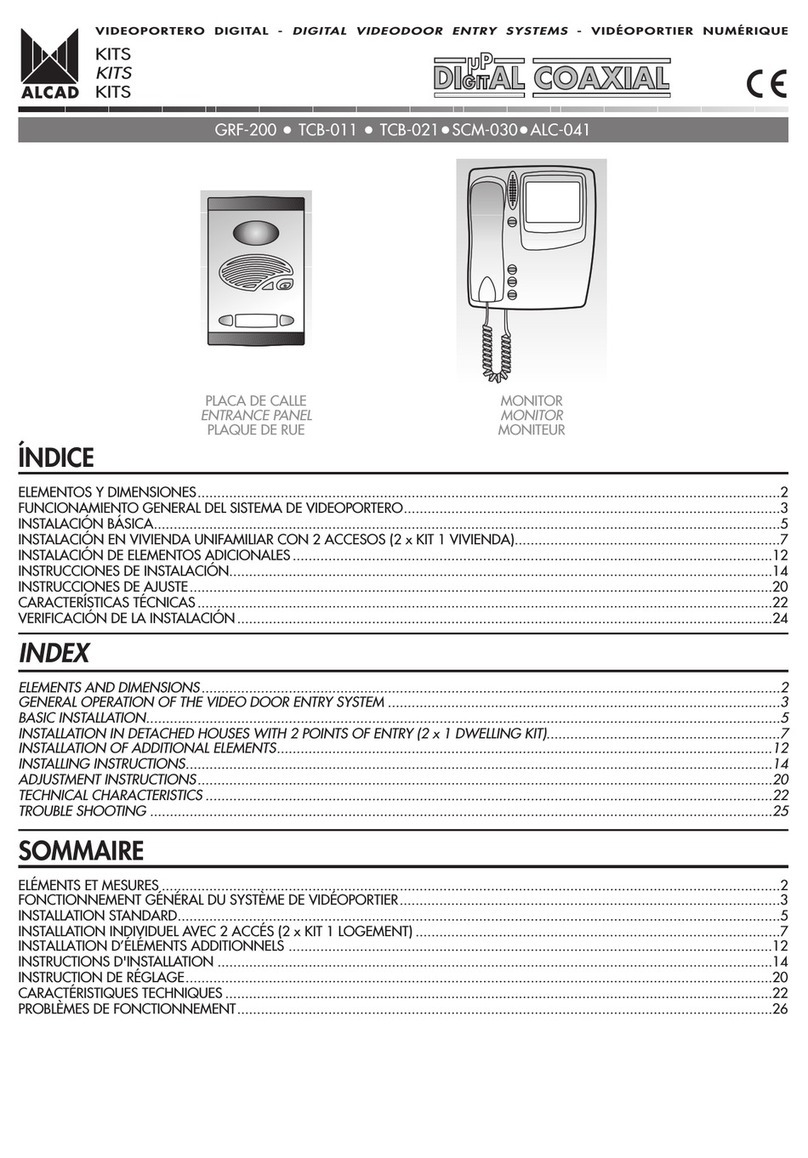
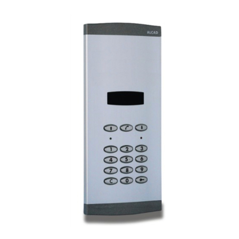
Alcad 980 Series User manual

1 2 3
4 5 6
78
C0
9
1 2 3
4 5 6
78
C0
9
VIDEOPORTERO DIGITAL - DIGITAL VIDEO DOOR ENTRY SYSTEMS - VIDEOPORTIER NUMÉRI UE
ÍNDICE
DESCRIPCIÓN .......................................................................................................................................................................................2
ELEMENTOS Y DIMENSIONES ...............................................................................................................................................................2
FUNCIONAMIENTO DEL SISTEMA DIGITAL CON TECLADO....................................................................................................................4
INSTALACIÓN BÁSICA..........................................................................................................................................................................5
INSTALACIÓN CON 2 ACCESOS...........................................................................................................................................................7
URBANIZACIÓN 3 EDIFICIOS.1 ACCESO EXTERIOR .............................................................................................................................10
URBANIZACIÓN 3 EDIFICIOS, PULSADORES. 1 ACCESO EXTERIOR......................................................................................................14
INSTRUCCIONES DE CONEXIÓN ........................................................................................................................................................18
INSTRUCCIONES DE INSTALACIÓN Y AJUSTE......................................................................................................................................22
INSTRUCCIONES DE CONFIGURACIÓN DE PLACA DE CALLE...............................................................................................................24
CARACTERÍSTICAS TÉCNICAS .............................................................................................................................................................30
VERIFICACIÓN DE LA INSTALACIÓN ...................................................................................................................................................32
INDEX
DESCRIPTION .......................................................................................................................................................................................2
ELEMENTS AND DIMENSIONS ..............................................................................................................................................................2
OPERATION OF THE DIGITAL SYSTEM WITH KEYPAD .............................................................................................................................
BASIC INSTALLATION............................................................................................................................................................................5
INSTALLATION WITH 2 POINTS OF ENTRY.............................................................................................................................................7
HOUSING ESTATE 3 BUILDINGS. 1 EXTERNAL POINT OF ENTRY...........................................................................................................10
HOUSING ESTATE 3 BUILDINGS, PUSH-BUTTONS. 1 EXTERNAL POINT OF ENTRY ................................................................................1
CONNECTION INSTRUCTIONS ...........................................................................................................................................................18
INSTALLING AND ADJUSTMENT INSTRUCTIONS..................................................................................................................................22
ENTRANCE PANEL CONFIGURATION INSTRUCTIONS .........................................................................................................................2
TECHNICAL CHARACTERISTICS ...........................................................................................................................................................30
TROUBLE SHOOTING..........................................................................................................................................................................33
SOMMAIRE
DESCRIPTION .......................................................................................................................................................................................2
ELEMENTS ET MESURES ........................................................................................................................................................................2
FONCTIONNEMENT DU SYSTÈME NUMÉRIQUE À CLAVIER ...................................................................................................................4
INSTALLATION STANDARD....................................................................................................................................................................5
INSTALLATION AVEC 2 ACCÉS..............................................................................................................................................................7
RÉSIDENCE 3 BÂTIMENTS. 1 ACCÉS EXTÉRIEURE................................................................................................................................10
RÉSIDENCE 3 BÂTIMENTS, BOUTONS POUSSOIRS. 1 ACCÉS EXTÉRIEURE...........................................................................................14
CONSIGNES DE BRANCHEMENT........................................................................................................................................................18
INSTRUCTIONS D'INSTALLATION ET DE RÉGLAGE ...............................................................................................................................22
INSTRUCTIONS DE CONFIGURATION DE LA PLAQUE DE RUE..............................................................................................................24
CARACTÉRISTIQUES TECHNIQUES ......................................................................................................................................................30
PROBLÉMES DE FONCTIONNEMENT...................................................................................................................................................34
SISTEMA DE CONSERJERÍA CON TECLADO
CONCIERGE SYSTEM WITH KEYPAD UNIT
SISTÈME DE CONCIERGERIE AVEC CLAVIER
CONSERJERIA
CONCIERGE
CONCIERGERIE
PLACA DE CALLE
ENTRANCE PANEL
PLAQUE DE RUE
PDK-42600 PDK-44600

128 mm
291 mm
1 2 3
4 5 6
78
C0
9
12 mm
VIDEOPORTERO DIGITAL - DIGITAL VIDEO DOOR ENTRY SYSTEMS - VIDEOPORTIER NUMÉRI UE
ELEMENTOS Y DIMENSIONES - ELEMENTS AND DIMENSIONS - ELEMENTS ET MESURES
PLACA DE CALLE CON TECLADO - ENTRANCE PANEL WITH KEYPAD - PLA UE DE RUE AVEC CLAVIER
DESCRIPCIÓN - DESCRIPTION - DESCRIPTION
Sistema para instalaciones de edificios con uno o varios accesos y para ur anizaciones con varios edificios interiores (instalaciones de tamaño
medio/alto). Compati le con conserjería.
Características:
El sistema permite gestionar:
- Edificios de hasta 999 monitores/teléfonos (150 monitores/teléfonos por montante. Para mayor número de monitores/teléfonos, realice la
instalación en varias montantes. Consulte esquema correspondiente).
- Ur anizaciones de hasta 99 edificios con placa de calle con teclado. Hasta 999 monitores/teléfonos por edificio.
- Ur anizaciones de hasta 99 edificios con placa de calle con pulsadores. Hasta 96 monitores/teléfonos por edificio.
MODELO
TYPE
RÉFÉRENCE
CÓDIGO
CODE
CODE
A UTILIZAR EN
FOR USE IN
A UTILISER EN MODE
Edificios
Buildings
Bâtiments
Acceso exterior en ur anizaciones
External point of entry in estates
Accés exterieure dans des résidences
9800046 PDK-42600
9800048 PDK-44600
Nota: Para fijación a pared se precisa de caja de empotrar o caja de superficie de 7u 8 alturas.
Note: For fixing to a wall, a flush-mounted or surface wall-mounted box of 7 or 8 storeys is necessary.
Remarque: Pour une fixation mural, il faudra un oîtier encastra le ou un oîter saillie pour 7 ou 8 étages.
System for installations in buildings with one or several points of entry and for housing estates containing several buildings (medium- to large-
scale installations). Compatible with concierge system.
Chara teristi s:
The system makes it possible to manage:
- Buildings with up to 999 monitors/telephones (150 telephones per riser. For a greater number of telephones, carry out the installation in
several stages. See the appropriate diagram)
- Housing estates of up to 99 buildings with keypad entrance panel. Up to 999 monitors/telephones per building.
- Housing estates of up to 99 buildings with push-button entrance panel. Up to 96 monitors/telephones per building.
Système pour installation dimmeu les avec un ou plusieurs accès ou des résidences avec plusieurs âtiments de taille moyenne à grande le
composant. Compati le avec une conciergerie.
Caractéristiques:
Le système permet la gestion de:
- Bâtiments jusqu'à 999 moniteurs/téléphones. (150 moniteurs/téléphones par gaine technique. Réaliser linstallation sur une autre gaine
sil y a un plus grand nom re de moniteurs/téléphones. Voir schémas correspondants).
- Pour des résidences jusqu'à 99 âtiments avec plaque de rue à clavier. Jusqu'à 999 moniteurs/téléphones par âtiment.
- Pour des résidences jusqu'à 99 âtiments avec plaque de rue à outons poussoirs. Jusqu'à 96 moniteurs/téléphones par âtiment.
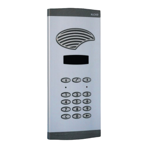
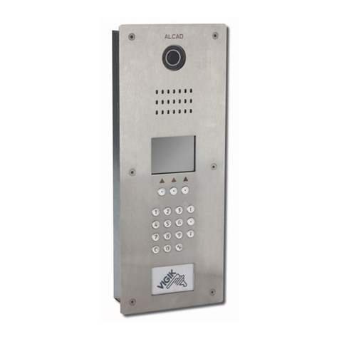
Placa de calle con grupo fónico digital, telecámara color par trenzado, display numérico y teclado numérico para instalaciones con conserjería.
Entrance panel with digital audio unit, colour video unit for twisted pair, numeric display and numeric keypad for installations with concierge
system.
9800046 PDK-42600
Plaque de rue avec groupe phonique numérique, caméra couleur par paire torsadée, écran numérique et clavier numérique pour des installations
avec conciergerie.
2

MÓDULOS INTERIORES - INSIDE MODULES - MODULES INTERIEURS
123
456
789
0C
1 2 3
4 5 6
78
C0
9
123
456
789
0C
VIDEOPORTERO DIGITAL - DIGITAL VIDEO DOOR ENTRY SYSTEMS - VIDEOPORTIER NUMÉRI UE
PLACA DE CALLE
ENTRANCE PANEL
PLA UE DE RUE
9640008
TCB-050
9610035
GRF-212
9610036
GRF-214
9650002
KPD-001
PDK-44600
PDK-42600
PLACA DE CALLE
ENTRANCE PANEL
PLAQUE DE RUE
Grupo fónico digital con display numérico para instalaciones con conserjería.
Digital audio unit with numeric display for installations with concierge system.
9610035 GRF-212
Groupe phonique numérique avec écran numérique pour installations avec conciergerie.
Grupo fónico digital con display numérico para cancela en instalaciones con conserjería.
Digital audio unit with numeric display for external entrance panels in installations with concierge system.
9610036 GRF-214
Groupe phonique numérique avec écran numérique pour plaques exterieures dans installations avec conciergerie.
Teclado numérico.
Numerical Keypad.
9650002 KPD-001
Clavier numérique.
Telecámara color para par trenzado.
Colour video unit for twisted pair.
9640008 TCB-050
Caméra couleur par paire torsadée.
Placa de calle con grupo fónico digital, telecámara color par trenzado, display numérico y teclado numérico para cancela en instalaciones
con conserjería.
Entrance panel with digital audio unit, colour video unit for twisted pair, numeric display and numeric keypad for external entrance in installations
with concierge system.
9800048 PDK-44600
Plaque de rue avec groupe phonique numérique, caméra couleur par paire torsadée, écran numérique et clavier numérique pour plaques
exterieures dans des installations avec conciergerie.
3

VIDEOPORTERO DIGITAL - DIGITAL VIDEO DOOR ENTRY SYSTEMS - VIDEOPORTIER NUMÉRI UE
FUNCIONAMIENTO DEL SISTEMA DIGITAL CON TECLADO
OPERATION OF THE DIGITAL SYSTEM WITH KEYPAD
FONCTIONNEMENT DU SYSTÈME NUMÉRI UE À CLAVIER
REALIZAR UNA LLAMADA A UNA VIVIENDA - MAKING A CALL TO A FLAT - REALISATION DUN APPEL A UN LOGEMENT
Para llamar a una vivienda, marque el código de la misma en el teclado de la placa de calle. El número de dígitos que de erá
teclear, dependerá del valor que haya configurado en la placa de calle (Posición 8 del menú de configuración, consulte páginas
27, 28 Y 29). El código marcado aparecerá mostrado en el display de la placa. A continuación pulse la tecla .
Nota: En caso de error al introducir el código, pulse la tecla C y marque de nuevo el código.
To make a call to a dwelling, key in its code on the keypad of the entrance panel. The number of digits which must be keyed in
will depend on the value which has been configured in the entrance panel (Position 8 from the configuration menu, pages 27, 28
and 29). As the code is keyed in, it will appear in the display of the panel. Press the key.
Note: If an error occurs while entering the code, press the C key and enter the code again.
Pour réaliser un appel à un logement, composez le code de celui-ci sur le clavier de la plaque de rue. Le nom re de chiffre quil
faudra composer, dépendra de la valeur configurée dans la plaque de rue (Position 8 dans le menu configuration, pages 27, 28 et
29). Le code composé apparaîtra sur le lécran de la plaque, ensuite appuyez la touche .
Remarque: En cas derreur dans lintroduction du code, appuyez la touche C et composer de nouveau le code.
Llamada a vivienda con código 12
Call made to dwelling with code 12
Appel à logement avec code 12
Vivienda con código 12
Dwelling with code 12
Logement avec code 12
ACTIVACIÓN DE ABREPUERTAS DESDE LA PLACA DE CALLE
ACTIVATING THE ELECTRIC LOCK FROM THE ENTRANCE PANEL
ACTIVATION DES GÂCHES DEPUIS LA PLA UE DE RUE
REALIZAR UNA LLAMADA A LA CONSERJERÍA - MAKING A CALL TO CONCIERGE - REALISATION DUN APPEL A CONCIERGERIE
Para llamar a la conserjería, pulse la tecla C en el teclado de la placa de calle y a continuación pulse la tecla .
To make call to conciergerie, press the C key on the keypad of the entrance panel and press the key.
Pour realiser un appel à le conciergerie, appuyez la touche
C
sur le clavier de la plaque de rue, ensuite appuyez la touche .
Pulse la tecla . A continuación introduzca uno de los códigos de apertura de puerta configurados previamente (Posiciones
14, 15, 16 y 17 del menú de configuración consulte páginas 27, 28 Y 29).
Nota: En caso de error al introducir el código de apertura de puerta, pulse la tecla C, a continuación pulse la tecla y
marque de nuevo el código. Con código correcto, el a repuertas se activará durante el tiempo que se haya configurado,
encendiéndose al mismo tiempo el led verde de la placa. Si el código no es correcto, la placa emitirá un tono de error,
encendiéndose al mismo tiempo el led rojo de la placa.
Press the key . Then enter one of the door-opening codes previously configured (Positions 1 , 15, 16 and 17 from the
configuration menu, pages 27, 28 and 29).
Note: If an error is made while entering the door-opening code, press the key C, then press the key and enter the code
again. If the code is correct, the electric lock will be activated for the period of time which has been configured; at the same time,
the green led on the entrance panel will light up. If the code is not correct, the panel will emit an error tone while the red led on
the panel will light up .
Appuyer la touche , ensuite introduire un des codes de la gâche configuré auparavant. (Positions 14, 15, 16 et 17 dans le
menu configuration, pages 27, 28 et 29)
Remarque: En cas derreur lors de lintroduction du code de la gâche, appuyer sur la touche C, ensuite appuyer sur la touche
et composer à nouveau le code. Avec le on code, la gâche sactivera pendant le temps configuré, en même temps la led
verte de la plaque sallumera. Si le code est incorrect la plaque émettra une tonalité derreur, en allumant en même temps la
led rouge de la plaque.
Código de apertura de puerta
Door-opening code
Code de la gâche Código incorrecto
Code not correct
Code incorrect
1 2 3
4 5 6
78
C0
9
1 2 3
4 5 6
78
C0
9
123
123
1 2 3
4 5 6
78
C0
9
1 2 3
4 5 6
78
C0
9
1 2 3
4 5 6
78
C0
9
1 2 3
4 5 6
78
C0
9
123
12
45
3
6
12
45
3
6
0
5
8
6
9
BRR
4

2 2
1 2 3
4 5 6
78
C0
9
T1+T1+T1+T1+T1+T1+
DIV-034
T1 T1 T1 T1 T1T1
T1+T1+T1+T1+T1+T1+
DIV-034
T1 T1 T1 T1 T1T1
T1+T1+T1+T1+T1+T1+
DIV-034
T1 T1 T1 T1 T1T1
VIDEOPORTERO DIGITAL - DIGITAL VIDEO DOOR ENTRY SYSTEMS - VIDEOPORTIER NUMÉRI UE
INSTALACIÓN BÁSICA - BASIC INSTALLATION - INSTALLATION STANDARD
ES UEMA UNIFILAR - SINGLE-WIRED DIAGRAM - SCHÉMA À UN FIL
Funcionamiento (Conserjería desactivada) - Operation (Con ierge unit dea tivated) - Fonctionnement (Conciergerie désactivée)
Configure la placa de calle como placa principal (P). (Vea "Configuración de placa de calle principal (P)", página 27)
La función de activación de a repuertas desde la placa de calle está ha ilitada en todo momento.
SISTEMA EN REPOSO
Los monitores están inactivos (funciones de comunicación con placa y apertura de puerta inha ilitadas). Si se levanta el auricular de un monitor
oirá un tono continuo. Es posi le activar el autoencendido del monitor.
SISTEMA ACTIVO. RECEPCIÓN DE LLAMADA
Sólo el monitor cuyo código coincida con el código marcado reci irá la llamada. Confirmación de llamada en placa. Si se levanta el auricular
de otro monitor se oirán tonos intermitentes y no podrá realizar el autoencendido. Si el auricular del monitor solicitado está descolgado o el
código no corresponde a ningún monitor, la placa emitirá tonos intermitentes. Con varios monitores en la vivienda, todos reci en la llamada.
El primer monitor en contestar, esta lece comunicación con la placa de calle.
Tiempo para contestar: Configura le (Posición 7 del menú de configuración, página 27).
Tiempo de conversación máximo: Configura le (Posición 6 del menú de configuración, página 27).
Durante dichos tiempos el display de la placa mostrará el código introducido.
Configure the panel as the main entrance panel (P). (See "Configuration of the main entrance panel (P)", page 27)
The function activating the electric lock from the entrance panel remains enabled at all times.
SYSTEM ON STANDBY
The monitors are inactive (communication with the entrance panel and door opening functions are disabled). If the handset of a monitor is lifted,
an uninterrupted tone will be heard. It is possible to activate the monitor's auto switch-on system.
SYSTEM ACTIVE. MAKING A CALL
Only the monitor whose code is identical to the code which has been entered will receive the call. Confirmation of the call on the entrance panel.
If the handset of another monitor is lifted, intermittent tones will be heard and the auto switch-on function will not operate. If the handset of the
requested monitor is off the hook or if the code does not correspond to any monitor, the panel will emit intermittent tones. When several monitors
are installed in the dwelling, all of them receive the call. The first monitor to be answered will establish communication with the the entrance panel.
Time setting to answer: Configurable (Position 7 from the configuration menu, page 27).
Maximum time setting for conversation: Configurable (Position 6 from the configuration menu, page 27).
During both these periods of time, the entrance panel display will show the code which has been entered.
Configurer la plaque de rue comme plaque principale (P) (Voir "Configuration de plaque principale (P)", page 27).
La fonction dactivation des gâches de la plaque est fonctionnelle à tout moment.
SYSTEME EN REPOS
Les moniteurs sont inactifs (fonctions de communication avec plaque et ouverture de porte inhi és). Si vous décrochez le com iné dun moniteur,
vous entendrez une tonalité continue. Il est possi le d'activer le système d'auto-allumage du moniteur.
SYSTEME ACTIF. RÉCEPTION D'APPELS
Le moniteur possédant ce numéro recevra lappel. Confirmation de lappel en plaque. Si vous décrochez le com iné dun autre moniteur, vous
entendrez une tonalité intermittente et ne pouvant pas activer l'auto allumage. Si le com iné du moniteur sollicité est décroché ou le code ne
correspond à aucun moniteur, la plaque émettra des tonalités intermittentes. Si le logement est équipé de plusieurs postes intérieurs, ils reçoivent
tous l'appel en même temps. Le moniteur qui est utilisé pour répondre à l'appel est le seul à rester en marche.
Temps pour répondre: Configura le (Position 7 dans le menu configuration, page 27).
Temps de conversation disponi le: Configura le (Position 6 dans le menu configuration, page 27).
Pendant ce temps lécran de la plaque affichera le code introduit.
PDK-42600 PTN-00000
1 mm 2
TABLA DE SECCIONES
AWG
1,1 mm 17
SECTION TABLE
TABLEAU DE SECTIONS
0,8 mm 20
1,1 mm 17
Hasta 100 m - Up to 100 m - Jusqu'à 100 m
Hasta 25 m - Up to 25 m - Jusqu'à 25 m
0,6 mm 22
0.25 mm2
0,5 mm 2
1 mm 2
ABR-011
(2)
MVC-002
+
SCM-040
(2) Máx. 15 Vdc, 0,5 A
ALM-040
(230 V )ALC-070
(230 V )
DIV-034
5
230 V V
2
2
2
2
2
2
22
230V~
++
<50m
<50m
<50m
1 2 3
4 5 6
78
C
0
9
INSTALACIÓN DE CONSERJERÍA CON MONITOR
INSTALLATION OF CONCIERGE SYSTEM WITH MONITOR
INSTALLATION DU CONCIERGERIE AVEC MONITEUR
CONSERJERÍA
CONCIERGE
CONCIERGERIE
ALM-040
(230 V )
ALC-070
(230 V )
230 V V
2
2
230V~
++
2
(1)
(1) Exclusivamente en instalación con conserjería
Only in installations with concierge unit
Uniquement dans des installations avec conciergerie

T1+T1+T1+T1+T1+T1+
DIV-034
cod.9730015
T1 T1 T1 T1 T1T1
T1+T1+T1+T1+T1+T1+
DIV-034
cod.9730015
T1 T1 T1 T1 T1T1
T1+T1+T1+T1+T1+T1+
DIV-034
cod.9730015
T1 T1 T1 T1 T1T1
KPD-001
cod. 9650002
OUT
IN
19
Made in Spain
230V~
++
T1+
T1+
25
26
27
24
T1
S5
T1
S2 D1 D2
T1+
T1+
25
26
27
24
T1
S5
T1
S2 D1 D2
VIDEOPORTERO DIGITAL - DIGITAL VIDEO DOOR ENTRY SYSTEMS - VIDEOPORTIER NUMÉRI UE
ABR-011
SCM-040
ALC-070
230 V
Tierra
Earth
Terre
INSTALACIÓN BÁSICA - BASIC INSTALLATION - INSTALLATION STANDARD
230 V
ALM-040
Notas: Consulte la hoja de normas de la conserjería para instalar la conserjería con monitor.
Para conectar la placa de calle con directorio, consulte "Conexión PTN-00000", página 18.
Notes: To install the concierge unit with monitor, consult the concierge unit datasheet.
To connect the entrance panel with directory, see "How to connect PTN-00000", page 18.
Remarques: Consulter la page de spécifications de la conciergerie pour installer la conciergerie avec moniteur
Pour connecter la plaque de rue avec directoire, voir "Branchement PTN-00000", page 18.
TCB-050
GRF-212
DIV-034
6
220 Ohm
D4 D5D4D5D3 D2 D2 D3
++
D1 D2
NO2 Ctrl2NC2
C2
C1
NO1 NC1 Ctrl1
22
12
12c
11
+
V
~
230 V
V
~
T2_
T2+T2_T2+T1_
T1+T4_T4+
19
R1
BJ1
R1
BJ1
120 Ohm
1 2 3
4 5 6
78
C
0
9
INSTALACIÓN DE CONSERJERÍA CON MONITOR
INSTALLATION OF CONCIERGE SYSTEM WITH MONITOR
INSTALLATION DU CONCIERGERIE AVEC MONITEUR
CONSERJERÍA
CONCIERGE
CONCIERGERIE
ALM-040
(230 V )
ALC-070
(230 V )
230 V V
2
2
230V~
++
2
(1)
(1) Exclusivamente en instalación con conserjería
Only in installations with concierge unit
Uniquement dans des installations avec conciergerie
(1)

1 mm 2
TABLA DE SECCIONES
AWG
1,1 mm 17
SECTION TABLE
TABLEAU DE SECTIONS
0,8 mm 20
1,1 mm 17
Hasta 100 m - Up to 100 m - Jusqu'à 100 m
Hasta 25 m - Up to 25 m - Jusqu'à 25 m
0,6 mm 22
0.25 mm2
0,5 mm 2
1 mm 2
230V~
++
2 2
2
2
2
2
2
2
2
2
2
2
2
2
2
1 2 3
4 5 6
78
C0
9
1 2 3
4 5 6
78
C0
9
230 V V230 V V
T1+T1+T1+T1+T1+T1+
DIV-034
T1 T1 T1 T1 T1T1
T1+T1+T1+T1+T1+T1+
DIV-034
T1 T1 T1 T1 T1T1
T1+T1+T1+T1+T1+T1+
DIV-034
T1 T1 T1 T1 T1T1
230V~
++
VIDEOPORTERO DIGITAL - DIGITAL VIDEO DOOR ENTRY SYSTEMS - VIDEOPORTIER NUMÉRI UE
ES UEMA UNIFILAR - SINGLE-WIRED DIAGRAM - SCHÉMA À UN FIL
Funcionamiento (Conserjería desactivada) - Operation (Con ierge unit dea tivated) - Fonctionnement (Conciergerie désactivée)
Configure una de las placas de calle como placa principal (P) (Vea "Configuración de placa de calle principal (P)", página 27). Dicha placa
de calle se activará cuando realice el autoencendido desde el monitor. Configure el resto de placas, como placas secundarias (S) (Vea
"Configuración de placa de calle secundaria (S)", página 28).
La función de activación de a repuertas desde las placas de calle está ha ilitada en todo momento.
SISTEMA EN REPOSO
Los monitores están inactivos (funciones de comunicación con placa y apertura de puerta inha ilitadas). Si se levanta el auricular de un monitor
oirá un tono continuo. Es posi le activar el sistema de autoencendido del monitor.
SISTEMA ACTIVO. RECEPCIÓN DE LLAMADA
Sólo el monitor cuyo código coincida con el código marcado reci irá la llamada. Confirmación de llamada en placa. El tono de llamada será
diferente si la llamada ha sido realizada desde la placa de calle principal o de otra placa. Si se levanta el auricular de otro monitor se oirán
tonos intermitentes y no podrá realizar el autoencendido. Si el auricular del monitor solicitado está descolgado o el código no corresponde a
ningún monitor, la placa emitirá tonos intermitentes. Con varios monitores en la vivienda, todos reci en la llamada. El primer monitor en contestar,
esta lece comunicación con la placa de calle.
Tiempo para contestar: Configura le (Posición 7 del menú de configuración).
Tiempo de conversación máximo: Configura le (Posición 6 del menú de configuración).
Durante dichos tiempos el display de la placa mostrará el código introducido. Las otras placas quedan inha ilitadas ( loqueadas). El display
de estas placas indica el tiempo de loqueo restante.
PDK-42600 PTN-00000 PDK-42600 PTN-00000
ABR-011
(1)
ABR-011
(1)
MVC-002
+
SCM-040
(2) Máx. 15 Vdc, 0,5 A
ALM-040
(230 V )ALC-070
(230 V ) ALC-070
(230 V ) ALM-040
(230 V )
INSTALACIÓN CON 2 ACCESOS - INSTALLATION WITH 2 POINTS OF ENTRY - INSTALLATION AVEC 2 ACCÉS
DIV-034
7
<50m
<50m
<50m
1 2 3
4 5 6
78
C
0
9
INSTALACIÓN DE CONSERJERÍA CON MONITOR
INSTALLATION OF CONCIERGE SYSTEM WITH MONITOR
INSTALLATION DU CONCIERGERIE AVEC MONITEUR
CONSERJERÍA
CONCIERGE
CONCIERGERIE
ALM-040
(230 V )
ALC-070
(230 V )
230 V V
2
2
230V~
++
2
(1)
(1) Exclusivamente en instalación con conserjería
Only in installations with concierge unit
Uniquement dans des installations avec conciergerie
(1)

VIDEOPORTERO DIGITAL - DIGITAL VIDEO DOOR ENTRY SYSTEMS - VIDEOPORTIER NUMÉRI UE
Configurer une des plaques de rue comme principale (P) (Voir "Configuration de plaque principale (P)", page 27). Cette plaque de rue sera
celle qui s'activerá lors the autoallumage du moniteur. Configurer les autres plaques, comme plaques secondaires (S) (Voir "Configuration de
plaque secondaire (S)", page 28).
La fonction dactivation des gâches des plaques est fonctionnelle à tout moment.
SYSTEME EN REPOS
Les moniteurs sont inactifs (fonctions de communication avec plaque et ouverture de porte inhi és). Si vous décrochez le com iné dun moniteur,
vous entendrez une tonalité continue. Il est possi le d'activer le système d'auto-allumage du moniteur.
SYSTEME ACTIF. RÉCEPTION D'APPELS
Le moniteur possédant ce numéro recevra lappel. Confirmation de lappel en plaque. La tonalité de lappel sera différente si lappel est réalisé
de la plaque de rue principale ou dune autre plaque.
Si vous décrochez le com iné dun autre moniteur, vous entendrez une tonalité intermittente et ne pouvant pas activer l'auto allumage. Si le
com iné du moniteur sollicité est décroché ou le code ne correspond à aucun moniteur, la plaque émettra des tonalités intermittentes. Si le
logement est équipé de plusieurs postes intérieurs, ils reçoivent tous l'appel en même temps. Le moniteur qui est utilisé pour répondre à l'appel
est le seul à rester en marche.
Temps pour répondre: Configura le (Position 7 dans le menu configuration).
Temps de conversation disponi le: Configura le (Position 6 dans le menu configuration).
Pendant ce temps lécran de la plaque affichera le code introduit. Lautre plaque est inhi ée et lécran de cette plaque indique le temps de
locage restant.
Configure one of the entrance panels as the main panel (P) (See "Configuration of the main entrance panel (P)", page 27) This entrance panel
will be activated when the auto switch-on function is used from the monitor. Configure the remaining panels as secondary panels (S) (See
"Configuration of the secondary entrance panel (S)", page 28).
The function activating the electric lock from the entrance panels remains enabled at all times.
SYSTEM ON STANDBY
The monitors are inactive (communication with the entrance panel and door opening functions are disabled). If the handset of a monitor is lifted,
an uninterrupted tone will be heard. It is possible to activate the monitor's auto switch-on system.
SYSTEM ACTIVE. MAKING A CALL
Only the monitor whose code is identical to the code which has been entered will receive the call. Confirmation of the call on the entrance panel.
The call tone will be different for calls from the main entrance panel and calls from other the other panel.
If the handset of another monitor is lifted, intermittent tones will be heard and the auto switch-on function will not operate. If the handset of the
requested monitor is off the hook or if the code does not correspond to any monitor, the panel will emit intermittent tones. When several monitors
are installed in the dwelling, all of them receive the call. The first monitor to be answered will establish communication with the the entrance panel.
Time setting to answer: Configurable (Position 7 from the configuration menu).
Maximum time setting for conversation: Configurable (Position 6 from the configuration menu).
During both these periods of time, the entrance panel display will show the code which has been entered. The other panels will be deactivated
(blocked). The display of these panels will show how much longer the panels will remain blocked.
8

KPD-001
cod. 9650002
OUT
IN
19
Made in Spain
KPD-001
cod. 9650002
OUT
IN
19
Made in Spain
230V~
++
230V~
++
T1+
T1+
25
26
27
24
T1
S5
T1
S2 D1 D2
T1+
T1+
25
26
27
24
T1
S5
T1
S2 D1 D2
T1+T1+T1+T1+T1+T1+
DIV-034
cod.9730015
T1 T1 T1 T1 T1T1
T1+T1+T1+T1+T1+T1+
DIV-034
cod.9730015
T1 T1 T1 T1 T1T1
T1+T1+T1+T1+T1+T1+
DIV-034
cod.9730015
T1 T1 T1 T1 T1T1
VIDEOPORTERO DIGITAL - DIGITAL VIDEO DOOR ENTRY SYSTEMS - VIDEOPORTIER NUMÉRI UE
INSTALACIÓN CON 2 ACCESOS - INSTALLATION WITH 2 POINTS OF ENTRY - INSTALLATION AVEC 2 ACCÉS
ALC-070 (230 V )
230 V
Tierra
Earth
Terre
ABR-011
ALC-070 (230 V )
Tierra
Earth
Terre
ABR-011
SCM-040
230 V
230 V
ALM-040
230 V
ALM-040
Notas: Consulte la hoja de normas de la conserjería para instalar la conserjería con monitor.
Para conectar la placa de calle con directorio, consulte "Conexión PTN-00000", página 18.
Notes: To install the concierge unit with monitor, consult the concierge unit datasheet.
To connect the entrance panel with directory, see "How to connect PTN-00000", page 18.
Remarques: Consulter la page de spécifications de la conciergerie pour installer la conciergerie avec moniteur
Pour connecter la plaque de rue avec directoire, voir "Branchement PTN-00000", page 18.
DIV-034
TCB-050 TCB-050
GRF-212 GRF-212
9
220 Ohm 220 Ohm
NO2 Ctrl2NC2
C2
C1
NO1 NC1 Ctrl1
22
12
12c
11
+
V
~
D4 D5D4D5
++
D1 D2 D3 D2 D2 D3
NO2 Ctrl2NC2
C2
C1
NO1 NC1 Ctrl1
22
12
12c
11
+
V
~
D4 D5D4D5
++
D1 D2 D3 D2 D2 D3
R1
BJ1
R1
BJ1
230 V
V
~
230 V
V
~
T1_
T1+T4_T4+
T2_
T2+T2_T2+T2_
T2+T2_T2+T1_
T1+T4_T4+
19 19
120 Ohm
1 2 3
4 5 6
78
C
0
9
INSTALACIÓN DE CONSERJERÍA CON MONITOR
INSTALLATION OF CONCIERGE SYSTEM WITH MONITOR
INSTALLATION DU CONCIERGERIE AVEC MONITEUR
CONSERJERÍA
CONCIERGE
CONCIERGERIE
ALM-040
(230 V )
ALC-070
(230 V )
230 V V
2
2
230V~
++
2
(1)
(1) Exclusivamente en instalación con conserjería
Only in installations with concierge unit
Uniquement dans des installations avec conciergerie
(1)

2
2
2
2
2
222
2
2
2
2
2
2
2
2
2
2
22
2
2
2
2
2
2
2 2
2
2
2
2
2
2
2
2
2
2
1 mm 2
TABLA DE SECCIONES
AWG
1,1 mm 17
SECTION TABLE
TABLEAU DE SECTIONS
0,8 mm 20
1,1 mm 17
Hasta 100 m - Up to 100 m - Jusqu'à 100 m
Hasta 25 m - Up to 25 m - Jusqu'à 25 m
0,6 mm 22
0.25 mm2
0,5 mm 2
1 mm 2
1 2 3
4 5 6
78
C0
9
1 2 3
4 5 6
78
C0
9
1 2 3
4 5 6
78
C0
9
1 2 3
4 5 6
78
C
0
9
DIV-134
15 V
T1+T1+T1+T1+T1+T1
12 V
T1 T1 T1T1
T1+T1+T1+T1+T1+T1+
DIV-034
T1 T1 T1 T1 T1T1
T1+T1+T1+T1+T1+T1+
DIV-034
T1 T1 T1 T1 T1T1
T1+T1+T1+T1+T1+T1+
DIV-034
T1 T1 T1 T1 T1T1
T1+T1+T1+T1+T1+T1+
DIV-034
T1 T1 T1 T1 T1T1
T1+T1+T1+T1+T1+T1+
DIV-034
T1 T1 T1 T1 T1T1
T1+T1+T1+T1+T1+T1+
DIV-034
T1 T1 T1 T1 T1T1
VIDEOPORTERO DIGITAL - DIGITAL VIDEO DOOR ENTRY SYSTEMS - VIDEOPORTIER NUMÉRI UE
ES UEMA UNIFILAR - SINGLE-WIRED DIAGRAM - SCHÉMA À UN FIL
PTN-00000 PTN-00000
PDK-44600 PTN-00000
PTN-00000
URBANIZACIÓN 3 EDIFICIOS. 1 ACCESO EXTERIOR
ESTATE 3 BUILDINGS. 1 EXTERNAL POINT OF ENTRY
RÉSIDENCE 3 BÂTIMENTS. 1 ACCÉS EXTÉRIEURE
EDIFICIO 2 - BUILDING 2 - BÂTIMENT 2 EDIFICIO 3 - BUILDING 3 - BÂTIMENT 3EDIFICIO 1 - BUILDING 1 - BÂTIMENT 1
MVC-002
+
SCM-040
MVC-002
+
SCM-040
MVC-002
+
SCM-040
ABR-011
(2)
PDK-42600 PDK-42600 PDK-42600
ACCESO EXTERIOR
EXTERNAL POINT OF ENTRY
ACCÉS EXTÉRIEURE
ABR-011
(2)
(2) Máx. 15 Vdc, 0,5 A
230V~
++
ABR-011
(2) ABR-011
(2)
ALM-040
(230 V )ALC-070
(230 V )
DIV-034 DIV-034 DIV-034
DIV-134
ALC-070 (230 V )
230V~
++
ALM-040
(230 V )
ALC-070 (230 V )
230V~
++
ALM-040
(230 V )
ALC-070 (230 V )
230V~
++
ALM-040
(230 V )
10
230 V V
<50m
<50m
<50m
<50m
<50m
<50m
230 V V230 V V230 V V
1 2 3
4 5 6
78
C
0
9
INSTALACIÓN DE CONSERJERÍA CON MONITOR
INSTALLATION OF CONCIERGE SYSTEM WITH MONITOR
INSTALLATION DU CONCIERGERIE AVEC MONITEUR
CONSERJERÍA
CONCIERGE
CONCIERGERIE
ALM-040
(230 V )
ALC-070
(230 V )
230 V V
2
2
230V~
++
2
(1)
(1) Exclusivamente en instalación con conserjería
Only in installations with concierge unit
Uniquement dans des installations avec conciergerie

VIDEOPORTERO DIGITAL - DIGITAL VIDEO DOOR ENTRY SYSTEMS - VIDEOPORTIER NUMÉRI UE
Funcionamiento (Conserjería desactivada) - Operation (Con ierge unit dea tivated) - Fonctionnement (Conciergerie désactivée)
Configure la placa de calle del acceso exterior, como placa exterior (E) (Vea "Configuración de placa de calle acceso exterior (E)", página
29). Configure la placa de calle de cada edificio como placa principal (P) (Vea "Configuración de placa de calle principal (P)", página 27).
Dicha placa de calle se activará cuando realice el autoencendido desde el monitor.
La función de activación de a repuertas desde las placas de calle está ha ilitada en todo momento en todas las placas.
SISTEMA EN REPOSO
Los monitores están inactivos (funciones de comunicación con placa y apertura de puerta inha ilitadas). Si se levanta el auricular de un monitor
oirá un tono continuo. Es posi le activar el sistema de autoencendido del monitor.
SISTEMA ACTIVO. RECEPCIÓN DE LLAMADA
Sólo el monitor cuyo código coincida con el código marcado reci irá la llamada. Confirmación de llamada en placa. Si se levanta el auricular
de otro monitor del mismo edificio se oirán tonos intermitentes y no podrá realizar el autoencendido. Si el auricular del monitor solicitado está
descolgado o el código no corresponde a ningún monitor, la placa emitirá tonos intermitentes. Con varios monitores en la vivienda, todos
reci en la llamada. El primer monitor en contestar, esta lece comunicación con la placa de calle.
Tiempo para contestar: Configura le (Posición 7 del menú de configuración).
Tiempo de conversación máximo: Configura le (Posición 6 del menú de configuración).
Durante los tiempos de contestación y conversación, el display de la placa mostrará el código introducido. Las placas del resto de edificios
permanecen en reposo, a la espera de que se realice una llamada. Si la llamada se realiza desde el acceso exterior, las placas de calle del
edificio donde esté el monitor quedan inha ilitadas ( loqueadas). El display de estas placas indican el tiempo de loqueo restante.
Configure the entrance panel of the external point of entry as the external panel (E) (See "Configuration of exterior entrance panel (E)", page
29). Configure the entrance panel of each building as the main panel (P) (See "Configuration of the main entrance panel (P)", page 27). This
entrance panel will be activated when the auto switch-on function is used from the monitor.
The function activating the electric lock from the entrance panels remains enabled at all times.
SYSTEM ON STANDBY
The monitors are inactive (communication with the entrance panel and door opening functions are disabled). If the handset of a monitor is lifted,
an uninterrupted tone will be heard. It is possible to activate the monitor's switch-on system.
SYSTEM ACTIVE. MAKING A CALL
Only the monitor whose code is identical to the code which has been entered will receive the call. Confirmation of the call on the entrance panel.
If the handset of another monitor in the same building is picked up, intermittent tones will be heard and the auto switch-on function will not
operate. If the handset of the requested monitor is off the hook or if the code does not correspond to any monitor, the panel will emit intermittent
tones. When several monitors are installed in the dwelling, all of them receive the call. The first monitor to be answered will establish communication
with the the entrance panel.
Time setting to answer: Configurable (Position 7 from the configuration menu).
Maximum time setting for conversation: Configurable (Position 6 from the configuration menu).
During both these periods of time, the entrance panel display will show the code which has been entered. The panels of the other blocks will
remain on standby until a call has been made. If the call is made from the external point of entry, the entrance panel of the building where the
monitor is located will be deactivated (blocked). The display of this panel will show how much longer the panel will remain blocked.
Configurer la plaque de rue de laccès extérieure, comme plaque extérieure (Voir "Configuration de plaque d'entrée principale (E)", page 29).
Configurer la plaque de rue de chaque âtiment comme plaque principale (Voir "Configuration de plaque principale (P)", page 27). Cette
plaque de rue sera celle qui s'activerá lors the autoallumage du moniteur.
La fonction dactivation des gâches des plaques est fonctionnelle à tout moment.
SYSTEME EN REPOS
Les moniteurs sont inactifs (fonctions de communication avec plaque et ouverture de porte inhi és). Si vous décrochez le com iné dun moniteur,
vous entendrez une tonalité continue. Il est possi le d'activer le système d'auto-allumage du moniteur.
SYSTEME ACTIF. RÉCEPTION D'APPELS
Le moniteur possédant ce numéro recevra lappel. Confirmation de lappel en plaque. Si vous décrochez le com iné dun autre moniteur du
même âtiment, vous entendrez des tonalités intermittentes et ne pouvant pas activer l'auto allumage. Si le com iné du moniteur sollicité est
décroché ou le code ne correspond à aucun moniteur, la plaque émettra des tonalités intermittentes. Si le logement est équipé de plusieurs postes
intérieurs, ils reçoivent tous l'appel en même temps. Le moniteur qui est utilisé pour répondre à l'appel est le seul à rester en marche.
Temps pour répondre: Configura le (Position 7 dans le menu configuration).
Temps de conversation disponi le: Configura le (Position 6 dans le menu configuration).
Pendant ce temps lécran de la plaque affichera le code introduit. Les plaques des autres locs seront au repos, dans lattente dun nouvel appel.
Si lappel est réalisé de laccès extérieur, la plaque de rue où se trouve le moniteur est inhi ée. Lécran de cette plaque indique le temps de
locage restant.
11

KPD-001
cod. 9650002
OUT
IN
19
Made in Spain
DIV-134
230V~
++
T1+T1+T1+T1+T1+
DIV-134
cod.9730016
T1
15 V
12 V
+T1 T1 T1T1
V
VIDEOPORTERO DIGITAL - DIGITAL VIDEO DOOR ENTRY SYSTEMS - VIDEOPORTIER NUMÉRI UE
ABR-011
ALC-070
230 V
Tierra
Earth
Terre
Placa de calle acceso exterior
External entrance panel
Plaque de rue accés extérieure
URBANIZACIÓN 3 EDIFICIOS. 1 ACCESO EXTERIOR
ESTATE 3 BUILDINGS. 1 EXTERNAL POINT OF ENTRY
RÉSIDENCE 3 BÂTIMENTS. 1 ACCÉS EXTÉRIEURE
230 V
ALM-040
Notas: Consulte la hoja de normas de la conserjería para
instalar la conserjería con monitor.
Para conectar la placa de calle con directorio, consulte
"Conexión PTN-00000", página 18.
Notes: To install the concierge unit with monitor, consult
the concierge unit datasheet.
To connect the entrance panel with directory, see
"How to connect PTN-00000", page 18.
Remarques: Consulter la page de spécifications de la conciergerie
pour installer la conciergerie avec moniteur.
Pour connecter la plaque de rue avec directoire, voir
"Branchement PTN-00000", page 18.
TCB-050
GRF-214
12
220 Ohm
NO2 Ctrl2NC2
C2
C1
NO1 NC1 Ctrl1
22
12
12c
11
+
V
~
D4 D5D4D5
++
D5 D4 D4 D5
T1_
T1+T4_T4+
T2_
T2+T2_T2+
EDIFICIO 2
BUILDING 2
BÂTIMENT 2
EDIFICIO 1
BUILDING 1
BÂTIMENT 1
EDIFICIO 3
BUILDING 3
BÂTIMENT 3
230 V
V
~
19
1 2 3
4 5 6
78
C
0
9
INSTALACIÓN DE CONSERJERÍA CON MONITOR
INSTALLATION OF CONCIERGE SYSTEM WITH MONITOR
INSTALLATION DU CONCIERGERIE AVEC MONITEUR
CONSERJERÍA
CONCIERGE
CONCIERGERIE
ALM-040
(230 V )
ALC-070
(230 V )
230 V V
2
2
230V~
++
2
(1)
(1) Exclusivamente en instalación con conserjería
Only in installations with concierge unit
Uniquement dans des installations avec conciergerie

KPD-001
cod. 9650002
OUT
IN
19
Made in Spain
230V~
++
1 2 3
4 5 6
78
C0
9
1 2 3
4 5 6
78
C0
9
T1+
T1+
25
26
27
24
T1
S5
T1
S2 D1 D2
T1+T1+T1+T1+T1+T1+
DIV-034
cod.9730015
T1 T1 T1 T1 T1T1
T1+T1+T1+T1+T1+T1+
DIV-034
cod.9730015
T1 T1 T1 T1 T1T1
T1+
T1+
25
26
27
24
T1
S5
T1
S2 D1 D2
T1+T1+T1+T1+T1+T1+
DIV-034
T1 T1 T1 T1 T1T1
T1+T1+T1+T1+T1+T1+
DIV-034
T1 T1 T1 T1 T1T1
T1+T1+T1+T1+T1+T1+
DIV-034
T1 T1 T1 T1 T1T1
T1+T1+T1+T1+T1+T1+
DIV-034
T1 T1 T1 T1 T1T1
VIDEOPORTERO DIGITAL - DIGITAL VIDEO DOOR ENTRY SYSTEMS - VIDEOPORTIER NUMÉRI UE
ABR-011
ALC-070
230 V
PTN-00000
ALC-070
ABR-011
PDK-42600
230V~
++
MVC-002
+
SCM-040
230 V
PTN-00000
PDK-42600
MVC-002
+
SCM-040
Tierra
Earth
Terre
Placa de calle principal
Main entrance panel
Plaque de rue principale
230 V
ALM-040
ABR-011
ALM-040
230 V
DIV-034
TCB-050
DIV-034DIV-034
ALC-070
230V~
++
230 V
ALM-040
230 V
GRF-212
13
EDIFICIO 3
BUILDING 3
BÂTIMENT 3
220 Ohm
SCM-040
NO2 Ctrl2NC2
C2
C1
NO1 NC1 Ctrl1
22
12
12c
11
+
V
~
D4 D5D4D5
++
D1 D2 D3 D2 D2 D3
R1
BJ1
R1
BJ1
T1_
T1+T4_T4+
T2_
T2+T2_T2+
EDIFICIO 2
BUILDING 2
BÂTIMENT 2
EDIFICIO 1
BUILDING 1
BÂTIMENT 1
230 V
V
~
230 V V
120 Ohm
19
<50m
<50m
<50m
<50m
230 V V

222
2 2
2
2
2
2
2
22
2
2
2
2
2
22
2
2
2
2
2
2
2
2
2
2
2 2 2
22
1 mm 2
TABLA DE SECCIONES
AWG
1,1 mm 17
SECTION TABLE
TABLEAU DE SECTIONS
0,8 mm 20
1,1 mm 17
Hasta 100 m - Up to 100 m - Jusqu'à 100 m
Hasta 25 m - Up to 25 m - Jusqu'à 25 m
0,6 mm 22
0.25 mm2
0,5 mm 2
1 mm 2
1 2 3
4 5 6
78
C
0
9
230V~
++
DIV-134
15 V
T1+T1+T1+T1+T1+T1
12 V
T1 T1 T1T1
T1+T1+T1+T1+T1+T1+
DIV-034
T1 T1 T1 T1 T1T1
T1+T1+T1+T1+T1+T1+
DIV-034
T1 T1 T1 T1 T1T1
T1+T1+T1+T1+T1+T1+
DIV-034
T1 T1 T1 T1 T1T1
T1+T1+T1+T1+T1+T1+
DIV-034
T1 T1 T1 T1 T1T1
T1+T1+T1+T1+T1+T1+
DIV-034
T1 T1 T1 T1 T1T1
T1+T1+T1+T1+T1+T1+
DIV-034
T1 T1 T1 T1 T1T1
230V~
++
230V~
++
VIDEOPORTERO DIGITAL - DIGITAL VIDEO DOOR ENTRY SYSTEMS - VIDEOPORTIER NUMÉRI UE
ES UEMA UNIFILAR - SINGLE-WIRED DIAGRAM - SCHÉMA À UN FIL
URBANIZACIÓN 3 EDIFICIOS, PULSADORES. 1 ACCESO EXTERIOR
ESTATE 3 BUILDINGS, PUSH-BUTTONS. 1 EXTERNAL POINT OF ENTRY
RÉSIDENCE 3 BÂTIMENTS, BOUTONS POUSSOIRS. 1 ACCÉS EXTÉRIEURE
EDIFICIO 1 - BUILDING 1 - BÂTIMENT 1 EDIFICIO 2 - BUILDING 2 - BÂTIMENT 2 EDIFICIO 3 - BUILDING 3 - BÂTIMENT 3
MDN-475 MDN-475 MDN-475
MVC-002
+
SCM-040
ABR-011
(2)
MPD-004
+
COL-000
+
AIB-000
MVC-002
+
SCM-040
ABR-011
(2)
MPD-004
+
COL-000
+
AIB-000
MVC-002
+
SCM-040
ABR-011
(2)
MPD-004
+
COL-000
+
AIB-000
(2) Máx. 15 Vdc, 0,5 A
PDK-44600 PTN-00000
ACCESO EXTERIOR
EXTERNAL POINT OF ENTRY
ACCÉS EXTÉRIEURE
ABR-011
(2)
230V~
++
ALM-040
(230 V )ALC-070
(230 V )
ALC-070
(230 V )
DIV-134
DIV-034 DIV-034 DIV-034
ALC-070
(230 V )ALC-070
(230 V )
14
230 V V
<50m
<50m
<50m
<50m
<50m
<50m
1 2 3
4 5 6
78
C
0
9
INSTALACIÓN DE CONSERJERÍA CON MONITOR
INSTALLATION OF CONCIERGE SYSTEM WITH MONITOR
INSTALLATION DU CONCIERGERIE AVEC MONITEUR
CONSERJERÍA
CONCIERGE
CONCIERGERIE
ALM-040
(230 V )
ALC-070
(230 V )
230 V V
2
2
230V~
++
2
(1)
(1) Exclusivamente en instalación con conserjería
Only in installations with concierge unit
Uniquement dans des installations avec conciergerie

VIDEOPORTERO DIGITAL - DIGITAL VIDEO DOOR ENTRY SYSTEMS - VIDEOPORTIER NUMÉRI UE
Funcionamiento (Conserjería desactivada) - Operation (Con ierge unit dea tivated) - Fonctionnement (Conciergerie désactivée)
Configure la placa de calle del acceso exterior, como placa exterior (E) (Vea "Configuración de placa de calle acceso exterior (E)", página
29). Configure la placa de calle de cada edificio como placa principal (Deje el puente J1 colocado). Dicha placa de calle se activará cuando
realice el autoencendido desde el monitor.
La función de activación de a repuertas desde la placa de calle sólo está ha ilitada en la placa de acceso exterior.
SISTEMA EN REPOSO
Los monitores están inactivos (funciones de comunicación con placa y apertura de puerta inha ilitadas). Si se levanta el auricular de un monitor
oirá un tono continuo. Es posi le activar el sistema de autoencendido del monitor.
SISTEMA ACTIVO. RECEPCIÓN DE LLAMADA
Sólo el monitor cuyo código coincida con el código marcado reci irá la llamada. Confirmación de llamada en placa. Si se levanta el auricular
de otro monitor del mismo edificio se oirán tonos intermitentes y no podrá realizar el autoencendido. Si el auricular del monitor solicitado está
descolgado o el código no corresponde a ningún monitor, la placa emitirá tonos intermitentes. Con varios monitores en la vivienda, todos
reci en la llamada. El primer monitor en contestar, esta lece comunicación con la placa de calle.
Tiempo para contestar: En acceso exterior; configura le (Posición 7 del menú de configuración). En edificios interiores; consulte hoja de
normas del grupo fónico.
Tiempo de conversación máximo: En acceso exterior; configura le (Posición 6 del menú de configuración). En edificios interiores; consulte
hoja de normas del grupo fónico.
Durante los tiempos de contestación y conversación, las placas del resto de edificios permanecen en reposo, a la espera de que se realice una
llamada. Si la llamada se realiza desde el acceso exterior, el display de la placa mostrará el código introducido. La placa de calle del edificio
donde esté el monitor queda inha ilitada ( loqueada) el indicador rojo parpadeará.
Configure the entrance panel of the external point of entry as the external panel (E) (See "Configuration of exterior entrance panel (E)", page
29). Configure the entrance panel of each building as the main panel (Leave the J1 jumper installed). This entrance panel will be activated when
the auto switch-on function is used from the monitor.
The function activating the electric lock from the entrance panels only remains enabled in the external point of entry.
SYSTEM ON STANDBY
The monitors are inactive (communication with the entrance panel and door opening functions are disabled). If the handset of a monitor is lifted,
an uninterrupted tone will be heard. It is possible to activate the monitor's auto switch-on system.
SYSTEM ACTIVE. MAKING A CALL
Only the monitor whose code is identical to the code which has been entered will receive the call. Confirmation of the call on the entrance panel.
If the handset of another monitor in the same building is picked up, intermittent tones will be heard and the auto switch-on function will not
operate. If the handset of the requested monitor is off the hook or if the code does not correspond to any monitor, the panel will emit intermittent
tones. When several monitors are installed in the dwelling, all of them receive the call. The first monitor to be answered will establish communication
with the the entrance panel.
Time setting to answer: At the external point of entry; configurable (Position 7 from the configuration menu). In buildings inside the estate;
consult datasheet of the audio unit.
Maximum time setting for conversation: At the external point of entry; configurable (Position 6 from the configuration menu). In buildings
inside the estate; consult datasheet of the audio unit.
During the answering and conversation periods, the panels of other buildings remain on standby until a call is made. If the call is made from
the external point of entry, the panel display will show the code which has been entered. The entrance panel of the building where the monitor
is located remains deactivated (blocked) The red indicator will blink.
Configurer la plaque de rue de laccès extérieure, comme plaque extérieure (Voir "Configuration de plaque d'entrée principale (E)", page 29).
Configurer la plaque de rue de chaque âtiment comme plaque principale (Laissez le cavalier J1 monté). Cette plaque de rue sera celle qui
s'activerá lors the autoallumage du moniteur.
La fonction dactivation des gâches de la plaque soulement est fonctionnelle à l'accés exterieure.
SYSTEME EN REPOS
Les moniteurs sont inactifs (fonctions de communication avec plaque et ouverture de porte inhi és). Si vous décrochez le com iné dun moniteur,
vous entendrez une tonalité continue. Il est possi le d'activer le système d'auto-allumage du moniteur, si celui ci n'est pas utilisé.
SYSTEME ACTIF. RÉCEPTION D'APPELS
Le moniteur possédant ce numéro recevra lappel. Confirmation de lappel en plaque. Si vous décrochez le com iné dun autre moniteur du
même âtiment, vous entendrez des tonalités intermittentes et ne pouvant pas activer l'auto allumage. Si le com iné du moniteur sollicité est
décroché ou le code ne correspond à aucun moniteur, la plaque émettra des tonalités intermittentes. Si le logement est équipé de plusieurs postes
intérieurs, ils reçoivent tous l'appel en même temps. Le moniteur qui est utilisé pour répondre à l'appel est le seul à rester en marche.
Temps de réponse. A lextérieur est configura le (Position 7 dans le menu configuration). Dans des âtiments intérieurs; voir notice du groupe
phonique.
Temps de conversation maximal: À lextérieur est configura le (Position 6 dans le menu configuration). Dans des âtiments intérieurs; voir
notice du groupe phonique.
Pendant les temps de réponses et conversations, les plaques du reste des âtiments restent en repos, dans lattente dun nouvel appel. Si lappel
se réalise de laccès extérieur, lécran de la plaque montrera le code introduit. La plaque de rue du âtiment, où se trouve le moniteur, restera
inhi é . Lindicateur rouge clignotera.
15

KPD-001
cod. 9650002
OUT
IN
19
Made in Spain
DIV-134
230V~
++
T1+T1+T1+T1+T1+
DIV-134
cod.9730016
T1
15 V
12 V
+T1 T1 T1T1
V
VIDEOPORTERO DIGITAL - DIGITAL VIDEO DOOR ENTRY SYSTEMS - VIDEOPORTIER NUMÉRI UE
URBANIZACIÓN 3 EDIFICIOS, PULSADORES. 1 ACCESO EXTERIOR
ESTATE 3 BUILDINGS, PUSH-BUTTONS. 1 EXTERNAL POINT OF ENTRY
RÉSIDENCE 3 BÂTIMENTS, BOUTONS POUSSOIRS. 1 ACCÉS EXTÉRIEURE
ABR-011
ALC-070
230 V
Tierra
Earth
Terre
Placa de calle acceso exterior
External entrance panel
Plaque de rue accés extérieure
230 V
ALM-040
Notas: Consulte la hoja de normas de la conserjería para
instalar la conserjería con monitor.
Para conectar la placa de calle con directorio, consulte
"Conexión PTN-00000", página 18.
Notes: To install the concierge unit with monitor, consult
the concierge unit datasheet.
To connect the entrance panel with directory, see
"How to connect PTN-00000", page 18.
Remarques: Consulter la page de spécifications de la conciergerie
pour installer la conciergerie avec moniteur.
Pour connecter la plaque de rue avec directoire, voir
"Branchement PTN-00000", page 18.
TCB-050
GRF-214
16
220 Ohm
NO2 Ctrl2NC2
C2
C1
NO1 NC1 Ctrl1
22
12
12c
11
+
V
~
D4 D5D4D5
++
D5 D4 D4 D5
T1_
T1+T4_T4+
T2_
T2+T2_T2+
EDIFICIO 2
BUILDING 2
BÂTIMENT 2
EDIFICIO 1
BUILDING 1
BÂTIMENT 1
EDIFICIO 3
BUILDING 3
BÂTIMENT 3
230 V
V
~
19
1 2 3
4 5 6
78
C
0
9
INSTALACIÓN DE CONSERJERÍA CON MONITOR
INSTALLATION OF CONCIERGE SYSTEM WITH MONITOR
INSTALLATION DU CONCIERGERIE AVEC MONITEUR
CONSERJERÍA
CONCIERGE
CONCIERGERIE
ALM-040
(230 V )
ALC-070
(230 V )
230 V V
2
2
230V~
++
2
(1)
(1) Exclusivamente en instalación con conserjería
Only in installations with concierge unit
Uniquement dans des installations avec conciergerie

J2
19
J1
GRF-208
COL-000
cod. 9730030
IN
1
4
6
87
5
3
2
141310 1211 16915762435 8
1
12345678
SW1
18
OUT
D1 D5 D4 D3 D2D2
AIB-000
cod. 9730014
OUT
4321
V
230V~
++
230V~
++
T1+T1+T1+T1+T1+T1+
DIV-034
T1 T1 T1 T1 T1T1
T1+T1+T1+T1+T1+T1+
DIV-034
T1 T1 T1 T1 T1T1
T1+T1+T1+T1+T1+T1+
DIV-034
T1 T1 T1 T1 T1T1
T1+T1+T1+T1+T1+T1+
DIV-034
T1 T1 T1 T1 T1T1
T1+T1+T1+T1+T1+T1+
DIV-034
cod.9730015
T1 T1 T1 T1 T1T1
T1+
T1+
25
26
27
24
T1
S5
T1
S2 D1 D2
T1+T1+T1+T1+T1+T1+
DIV-034
cod.9730015
T1 T1 T1 T1 T1T1
T1+
T1+
25
26
27
24
T1
S5
T1
S2 D1 D2
230V~
++
VIDEOPORTERO DIGITAL - DIGITAL VIDEO DOOR ENTRY SYSTEMS - VIDEOPORTIER NUMÉRI UE
ABR-011
Placa de calle principal
Main entrance panel
Plaque de rue principale
AIB-000
COL-000
910111222
SC1
7
D1D2 D3
18
+
EDIFICIO 3 -BUILDING 3 - BÂTIMENT 3
MDN-475 MDN-475
ALC-070
MVC-002
+
SCM-040
MPD-004
+
COL-000
+
AIB-000
ABR-011
MVC-002
+
SCM-040
MPD-004
+
COL-000
+
AIB-000
ABR-011
EDIFICIO 1 -BUILDING 1 - BÂTIMENT 1 EDIFICIO 2 -BUILDING 2 - BÂTIMENT 2
ALC-070
230 V
Tierra
Earth
Terre
230 V
DIV-034 DIV-034
TCB-050
DIV-034
ALC-070
230 V
17
220 Ohm
J1
GRF-208
4321
18D2D3D4D5D2D1
V~
J1J1
EDIFICIO 1
BUILDING 1
BÂTIMENT 1
EDIFICIO 2
BUILDING 2
BÂTIMENT 2
EDIFICIO 3
BUILDING 3
BÂTIMENT 3
T1_
T1+T4_T4+
T2_
T2+T2_T2+
<50m
<50m
<50m
<50m
19
R1
BJ1
R1
BJ1
SCM-040
120 Ohm

IN
19
Made in Spain
D4 D5D4D5
+
D1 D2 D3 D2 D2 D3
KPD-001
cod. 9650002
OUT
IN
19
Made in Spain
NO2
11
+
C1
NO1 NC1 Ctrl1
22
12
Ctrl2NC2
C2
12c
D4 D5D4D5
++
D1 D2 D3 D2 D2 D3
VIDEOPORTERO DIGITAL - DIGITAL VIDEO DOOR ENTRY SYSTEMS - VIDEOPORTIER NUMÉRI UE
Iluminación continua de la placa con directorio
Continuous lighting of the panel with dire tory
Eclairage continu de la plaque avec répertoire
Las conexiones correspondientes a la iluminación de los tarjeteros de la placa de calle con directorio se pueden realizar de dos maneras
diferentes:
INSTRUCCIONES DE CONEXIÓN - CONNECTION INSTRUCTIONS - INSTRUCTIONS DE BRANCHEMENT
CONEXIÓN PTN-00000 - HOW TO CONNECT PTN-00000 - BRANCHEMENT PTN-00000
The connections corresponding to the lighting of the card-holders of the entrance panel with directory can be performed in two different ways:
Les connexions correspondantes à léclairage des portes cartes de la plaque de rue peuvent se réaliser de deux façons différentes:
Activación de la iluminación al pulsar cualquier tecla de la placa de calle
Turning on the lighting by pressing any key on the entran e panel
Activation de léclairage en appuyant sur nimporte quel touche de la plaque de rue
Nota: El tiempo que permanecerá la iluminación activada dependerá del valor que haya configurado para el relé 2.
(Posición 13 del menú de configuración).
Note: The length of time that the lighting remains on will depend on the value that has been configured for relay 2.
(Position 13 from the configuration menu).
Remarque: Le temps déclairage actif dépendra de la valeur de la configuration pour le relais 2.
(Position 13 dans le menu de configuration).
B
A
18

Para instalaciones de varios accesos, extraer la resistencia de las ornas (T2+,T2)
donde vaya a conectar el par trenzado (pasos 1 y 2).
For installations with several points of entry, extract the resistence from the terminals
(T2+,T2) where the twisted pair cable is to be connected (steps 1 and 2).
Pour des installations avec plusieurs accés, ôter la résistance des ornes (T2+, T2)
ou la paire torsadée va être connectée (point 1 et 2).
1
220 Ohm
2
T2+, T2
T1+, T1
T2+, T2
Grupo fónico
Audio unit
Groupe phonique
19
19
T1_
T1+T4_T4+
T2_
T2+T2_T2+
T1+,T1 Señal de vídeo hacia monitores - Vídeo signal to the monitors - Signal vidéo aux moniteurs
T2+,T2 Señal de vídeo varios accesos - Video signal installations with several points of entry
Signal vidéo installations avec plusieurs accés
T4+,T4 Señal de video acceso exterior ur anización - Video signal housing estate external point of entry
Signal vidéo accés extérieure residence
19 Control telecámara - Video unit control - Control d'une caméra
T1+T1+T1+T1+T1+T1+
DIV-034
cod.9730015
T1 T1 T1 T1 T1T1
T1+T1+T1+T1+T1+T1+
DIV-034
cod.9730015
T1 T1 T1 T1 T1T1
VIDEOPORTERO DIGITAL - DIGITAL VIDEO DOOR ENTRY SYSTEMS - VIDEOPORTIER NUMÉRI UE
BORNAS - TERMINALS - BORNES
CONEXIÓN TCB-050 - HOW TO CONNECT TCB-050 - BRANCHEMENT TCB-050
Telecámara
(Instalación varios accesos)
Video unit
(Installation with several points of entry)
Caméra
(Installation avec plusieurs accés)
Telecámara
(Instalación varios accesos)
Video unit
(Installation with several points of entry)
Caméra
(Installation avec plusieurs accés)
Distri uidor (Acceso exterior ur anización)
Splitter (Housing estate external point of entry)
Distri uteur (Accés extérieure résidence)
19

19
Made in Spain
19
Made in Spain
IN
15 V
BUS
D5 D4 D4 D5D5 D4 D4 D5
D1
IN
15 V
D2
BUS
D3 D5D2 D3D2 D4 D4 D5
VIDEOPORTERO DIGITAL - DIGITAL VIDEO DOOR ENTRY SYSTEMS - VIDEOPORTIER NUMÉRI UE
Teclado numérico
Numeric keypad
Clavier numérique
Alimentador
Power supply
Alimentation
Teléfonos
Telephones
Téléphones
D2,D1
D3
D2
D3
D2
CONEXIÓN GRF-212 - HOW TO CONNECT GRF-212 - BRANCHEMENT GRF-212
+,
Tensión de alimentación - Power supply voltage
Tension d'alimentation
D1, D2 BUS teléfonos - Telephones BUS - BUS téléphones
D3, D2 BUS placas - Panels BUS - BUS plaque
D5, D4 BUS acceso exterior - External point of entry BUS
BUS accés exterieure
BORNAS - TERMINALS - BORNES
D5, D4
Teclado numérico
Numerical keypad
Clavier numérique
Alimentador
Power supply
Alimentation
CONEXIÓN GRF-214 - HOW TO CONNECT GRF-214 - BRANCHEMENT GRF-214
+,
Tensión de alimentación - Power supply voltage
Tension d'alimentation
D5, D4 BUS acceso exterior - External point of entry BUS
BUS accés exterieure
BORNAS - TERMINALS - BORNES
D5, D4
GRF-212
GRF-214
Rojo
Red
Rouge
Blanco
White
Blanc
IN Conector teclado numérico - Numerical keypad connector
Connecteur clavier numérique
19 Alimentación (en instalación ásica) y control telecámara.
Alimentation (Basic installation) and video unit control.
Alimentation (Installation standard) et control d'une caméra.
Rojo
Red
Rouge
Blanco
White
Blanc
IN Conector teclado numérico - Numeric keypad connector
Connecteur clavier numérique
19 Control telecámara - Video unit control - Control d'une caméra.
Grupo fónico
(Instalación varios accesos)
(Instalación conserjería)
Audio unit
(Installation with several
points of entry)
(Installation concierge system)
Groupe phonique
(Installation avec plusieurs accés)
(Installation conciergerie)
Grupo fónico (Ur anizaciones)
(Instalación conserjería)
Audio unit (Housing estates)
(Installation concierge system)
Groupe phonique (Résidences)
(Installation conciergerie)
20
Telecámara
Video unit
Caméra
Telecámara
Video unit
Caméra
Other manuals for 980 Series
13
This manual suits for next models
4
Table of contents
Other Alcad Intercom System manuals

Alcad
Alcad TCB-040 User manual

Alcad
Alcad GRF-001 User manual

Alcad
Alcad MVC-141 User manual

Alcad
Alcad GRF-202 User manual

Alcad
Alcad TED-002 User manual

Alcad
Alcad TED-001 User manual

Alcad
Alcad GRF-400 User manual

Alcad
Alcad GRF-411 User manual

Alcad
Alcad 967 Series User manual

Alcad
Alcad GRF-302 User manual

Alcad
Alcad 963 Series User manual

Alcad
Alcad KVS-56121 User manual

Alcad
Alcad TED-001 User manual

Alcad
Alcad TCB-010 User manual

Alcad
Alcad GRF-200 User manual

Alcad
Alcad 960 Series User manual

Alcad
Alcad GRF-201 User manual

Alcad
Alcad GRF-304 User manual

Alcad
Alcad TCB-010 User manual

Alcad
Alcad 4+N User manual