Forge W-KIT-1-BK-1PC User manual
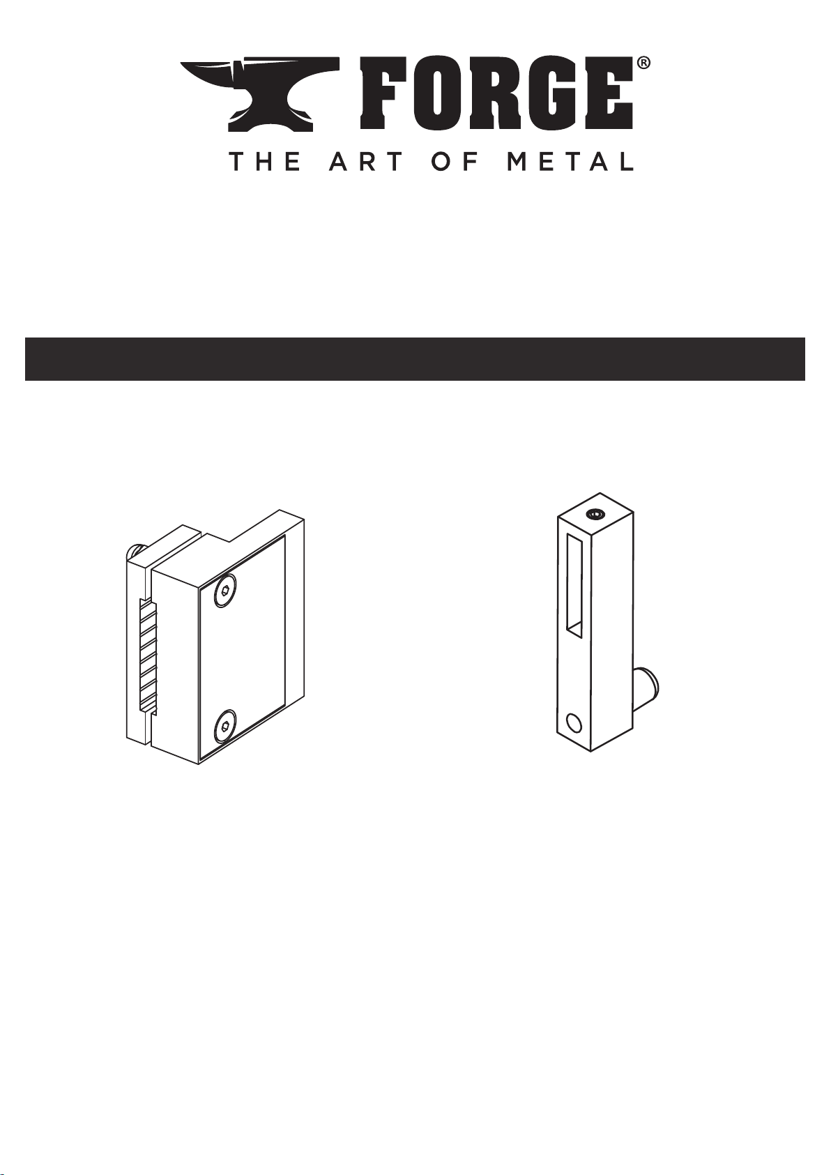
-If Door Stop 1 is included with your kit, please start on Page 2
-If Door Stop 2 is included with your kit, please start on Page 6
Door Stop 2Door Stop 1
Barn Door Trolley Kit
Table of Contents
Installation Manual
4310485
W-KIT-1-BK-1PC
Iron Black
1
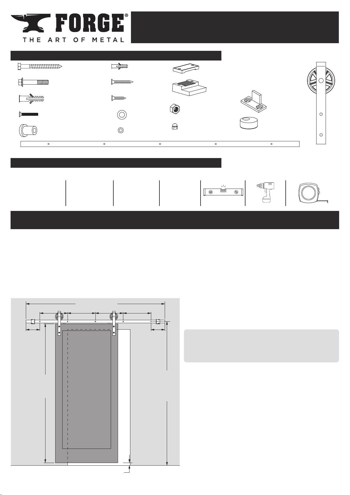
80” [2032mm]
A
A- 16” [406mm]
B- 8” [204mm]
Door
Height
(H)
(H)
plus
1-5/8”
[41.5mm]
3/8” [9.5mm] Gap
AAA
B B
2
1
4
2
2
4
4
4
4
2
2
2
4
44
5
5
5
Wrench/Socket Drill Bit Allen Wrench Driver Bit 2’-3’ Level Power Drill Tape Measure
1/2” (13mm)
9/16” (14mm)
11/16” (17mm)
3/32”
7/32”
1/4”
3/8”
7/16”
3mm #8 Phillips
12'
NOTE: This kit is best suited for doors up to 1-3/8”thick, up to 36” wide, and no more than
150 pounds.
Before installing the Rail, identify secure points to attach the Rail.
For most wall installations, it is necessary that the Lag Screws are secured to wall studs.
For Lag Screws that cannot be secured to a
wall stud, it will be necessary to use the
Wall Anchors to secure the Lag Screws
into the wall.
Home construction varies; holes may be
added to the Rail to allow Lag Screws
to attach to wall studs.
IMPORTANT:
If at least FOUR Lag Screws cannot
be secured to wall studs or other
structural points, DO NOT INSTALL
THIS RAIL KIT.
Barn Door Rail Kit
Parts Included
Recommended Tools
Planning
Installation Manual
4310485
W-KIT-1-BK-1PC
Iron Black
●READ ALL INSTRUCTIONS AND CHECK PARTS BEFORE STARTING INSTALLATION
●RETAIN ALL PACKING MATERIALS UNTIL INSTALLATION IS COMPLETE
Spacer
SS-10.1007
Door Guide
SS-10.1013
Door Stop Front
ss-10.1236
Door Stop Rear
ss-10.1239
Anti-Jump Pad
SS-10.1076
Waylon
Trolley
SS-20.1059
Floor Anchor
SS-10.1011
1-1/4” Screw
SS-10.1012
Nut (M10-1.5)
SS-10.1010
Acorn Nut (M5)
ss-10.1244
Washer
SS-10.1009
Washer (M5)
ss-10.1243
3/4” Screw
SS-10.1075
Socket Head Bolt (M5-0.8 x 35)
ss-10.1242
Bolt (M10-1.5 x 50)
SS-10.1077
Lag Screw
SS-10.1006
Wall Anchor
SS-10.1002
2

Socket Screws
WALL
X
Y
Z
T
D
E
W
Mark the location of pilot holes for the Lag Screws using a pencil, measuring tape, and level.
Refer to the diagram for proper hole spacing.
Home construction varies; holes may be added to the Rail to allow Lag Screws to attach
to wall studs. Use drill bits suitable for mild steel and a light oil such as a 3-in-1 oil to aid in
drilling. Use a 3/32” bit for a pilot hole. Use a 7/16” bit for the nished hole.
The holes should be located at a height from the oor 1-5/8” (41.5mm) greater than the door
height (H). If the oor is uneven or not level, measure from the highest point on the oor
around the door.
Proper hole location should leave a 3/8”(9.5mm) gap under the door.
IMPORTANT
If the rail is not installed level, the door may slide open or closed without warning.
Drill 7/32” pilot holes to locate the Lag Screws at each mark on the wall. For any pilot hole NOT
in line with a wall stud or structural member, drill a 3/8” hole and insert a Wall Anchor into the
hole.
2 - Mount the Rail
IMPORTANT
If the Door Stops will be located
between the outermost Lag
Screws, they should be placed
loose on the Rail at this time.
Place the Door Stop with the
rubber facing the Rail and the
socket screws facing OUT.
Door
Thickness
Trolley Top
to Rail
Door to
Rail Center
Bypass
Clearance
Trolley
Clearance
Bolt
Clearance
Door
Clearance
T D(1) (3) E W(3) X(2) Y(2) Z(2)
1-3/8” 6” 1-1/4” 2-1/2”3/8”1/8”1/2”
1” 6” 1-1/4” 2-1/2”3/8”1/8”7/8”
(1)Allow at least 3/4”clearance above the trolley.
(2)The nominal distance with the door hung to run vertical and the
wall straight and plumb. Improper installation, warped doors, extra
hardware, or decorative protrusions may reduce the clearance space.
(3)Any additional rail and hardware mounted with a bypass bracket
system should allow this amount of space or more for proper operation
of this barn rail kit.
Insert the Socket Head Bolts through the Front and Rear Door Stop sections. Add an M5
Washer and Acorn Nut to each Bolt as shown below. Do not fully tighten the bolts
1 - Drill Holes to Mount the Rail
Planning (continued)
3
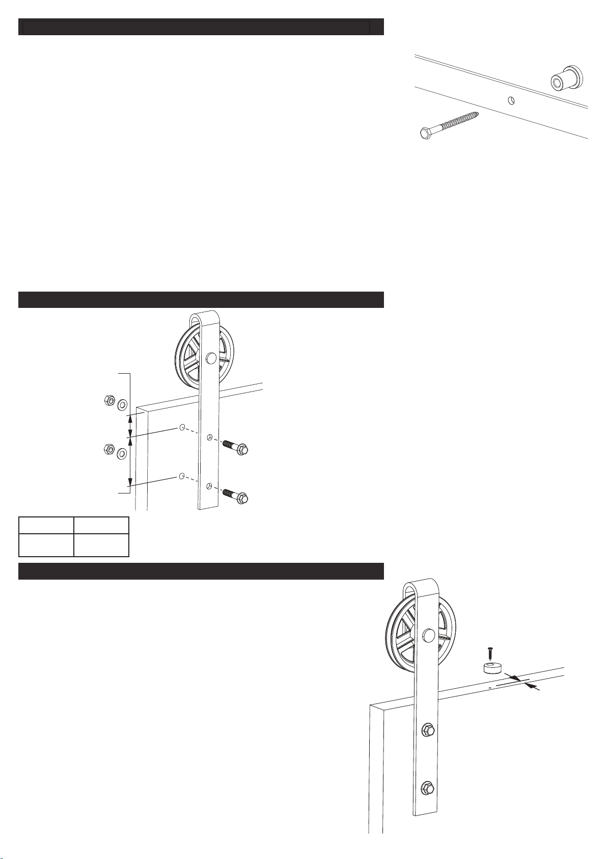
5/16”
(Rail not shown for clarity)
M N
1-5/8” 3-9/16”
M
N
IMPORTANT
The widest part of the Spacer should be placed on the wall.
Place a Lag Screw through the hole in the Rail aligning with the
outermost pilot hole on one side, through a Spacer, and drive
the Lag Screw into the pilot hole. DO NOT fully tighten Lag
Screw.
2 - Mount the Rail (Continued)
Repeat process for a Lag Screw on the opposite end of Rail. DO NOT fully tighten Lag Screw.
Insert remaining Lag Screws through Rail holes and Spacers, and drive into pilot holes. DO NOT
fully tighten Lag Screws.
After all Lag Screws and Spacers are in place, use a level on top of the Rail to make sure it is
properly level. While making sure the Rail is level, tighten all Lag Screws securely.
3 - Install Trolleys and Hang the Door
Mark the location of the holes for the Trolleys on
the front of the door as shown in the diagram.
Drill the holes using a 7/16” bit.
Insert the Bolts through the Trolley and the door.
Add a Washer and Nut to each Bolt. Hand
tighten both Nuts before securing with a
wrench.
Hang the door on the Rail. Make sure both
rollers are in contact with the Rail and that the
door is level.
4 - Install Anti-Jump Pads
Drill two 3/32” pilot holes in the top of the door and
located between and near the Trolleys, as shown
in the diagram, in order to mount the Anti-Jump
Pads.
Place the Anti-Jump Pads on the top of the door
and attach with the 3/4” Phillips Screws.
Make sure the Anti-Jump Pad is positioned so that
the hole is towards the front side of the door and
the body of the Pad is underneath the Rail.
4

(T)
plus
3/32”
(2mm)
Door
Thickness (T)
Floor
Anchor
1-1/4”
Screw
Locate the Door Guides on either side of the door, as close
to the doorway as possible. See the diagram for proper
Move the door to the desired closed position. Place a Door Stop so that the bumper contacts
the trolley and the socket screws facing out. Secure the Door Stop by tightening the socket
screw.
Move the door to the desired open position and repeat with the remaining Door Stop.
5 - Install Door Guides and Secure Door Stops
OTHER QUESTIONS?
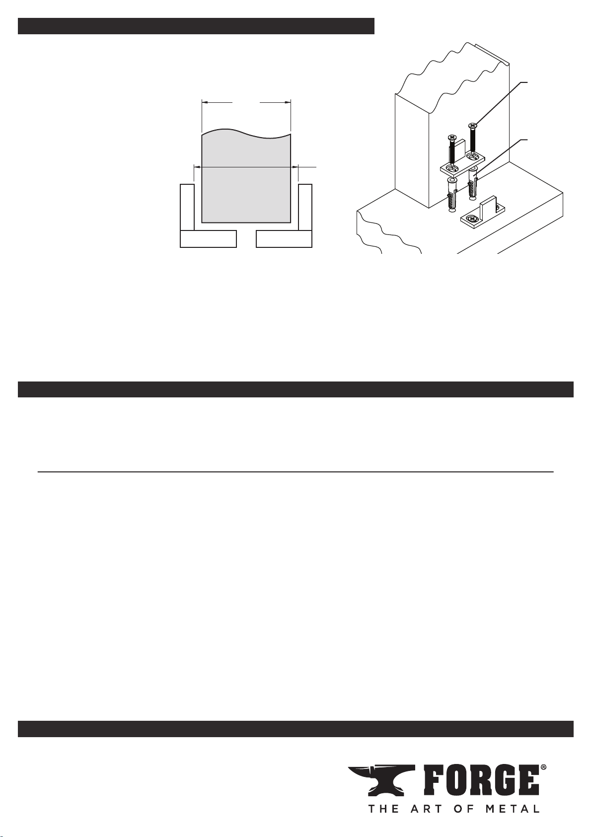
spacing.
If the oor is not solid
wood, it may be
necessary to use
the Floor Anchors in
addition to the screws.
Drill 3/32” pilot holes if
using screws only, or
1/4” pilot holes if using
Floor Anchors.
REV-06
NEED EXTRA PARTS or OPTIONAL ACCESSORIES?
Additional parts and accessories are available exclusively at
www.menards.com/barndoorhardware
or your local Menards store, including rails, rail connectors, spacer kits,
soft-close mechanisms, bypass brackets, locks, and handles.
NOTE: If installing a soft-close mechanism (431-0451), check the soft-close instructions
BEFORE beginning installation.
NOTE: If installing bypass brackets (431-0446, 431-0447, 431-0452), check the bypass bracket
instructions BEFORE beginning installation.
DO NOT RETURN TO THE STOREContact Customer Care
1-800-721-4191
Monday – Friday
8 - 5 Central Time
5
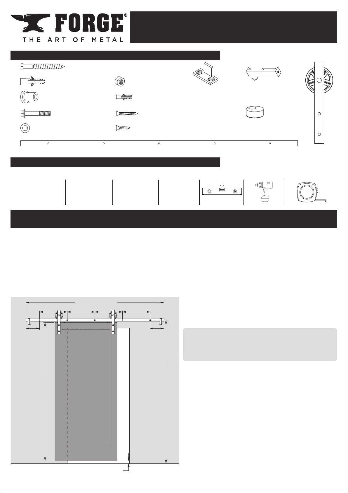
80” [2032mm]
A
A- 16” [406mm]
B- 8” [204mm]
Door
Height
(H)
(H)
plus
1-5/8”
[41.5mm]
3/8” [9.5mm] Gap
AAA
B B
2
5
4
2
2
4
4
42
1
2
4
5
5
Wrench/Socket Drill Bit Allen Wrench Driver Bit 2’-3’ Level Power Drill Tape Measure
1/2” (13mm)
9/16” (14mm)
11/16” (17mm)
3/32”
7/32”
1/4”
3/8”
7/16”
3mm #8 Phillips
12'
NOTE: This kit is best suited for doors up to 1-3/8”thick, up to 36” wide, and no more than
150 pounds.
Before installing the Rail, identify secure points to attach the Rail.
For most wall installations, it is necessary that the Lag Screws are secured to wall studs.
For Lag Screws that cannot be secured to a
wall stud, it will be necessary to use the
Wall Anchors to secure the Lag Screws
into the wall.
Home construction varies; holes may be
added to the Rail to allow Lag Screws
to attach to wall studs.
IMPORTANT:
If at least FOUR Lag Screws cannot
be secured to wall studs or other
structural points, DO NOT INSTALL
THIS RAIL KIT.
Barn Door Rail Kit
Parts Included
Recommended Tools
Planning
Installation Manual
4310485
W-KIT-1-BK-1PC
Iron Black
●READ ALL INSTRUCTIONS AND CHECK PARTS BEFORE STARTING INSTALLATION
●RETAIN ALL PACKING MATERIALS UNTIL INSTALLATION IS COMPLETE
Lag Screw
SS-10.1006
Door Guide
SS-10.1013
Door Stop
SS-10.1005
Anti-Jump Pad
SS-10.1076
Waylon
Trolley
SS-20.1059
Nut (M10-1.5)
SS-10.1010
Floor Anchor
SS-10.1011
1-1/4” Screw
SS-10.1012
3/4” Screw
SS-10.1075
Wall Anchor
SS-10.1002
Spacer
SS-10.1007
Bolt (M10-1.5 x 50)
SS-10.1077
Washer
SS-10.1009
Rail
SS-20.1147
6

Set Screw
WALL
X
Y
Z
T
D
E
W
Mark the location of pilot holes for the Lag Screws using a pencil, measuring tape, and level.
Refer to the diagram for proper hole spacing.
Home construction varies; holes may be added to the Rail to allow Lag Screws to attach
to wall studs. Use drill bits suitable for mild steel and a light oil such as a 3-in-1 oil to aid in
drilling. Use a 3/32” bit for a pilot hole. Use a 7/16” bit for the nished hole.
The holes should be located at a height from the oor 1-5/8” (41.5mm) greater than the door
height (H). If the oor is uneven or not level, measure from the highest point on the oor
around the door.
Proper hole location should leave a 3/8”(9.5mm) gap under the door.
IMPORTANT
If the rail is not installed level, the door may slide open or closed without warning.
Drill 7/32” pilot holes to locate the Lag Screws at each mark on the wall. For any pilot hole NOT
in line with a wall stud or structural member, drill a 3/8” hole and insert a Wall Anchor into the
hole.
2 - Mount the Rail
IMPORTANT
If the Door Stops will be located between the outermost
Lag Screws, they should be placed loose on the Rail at
this time.
Place the Door Stop with the rubber bumpers facing the
center of the Rail and the Set Screw facing UP.
Door
Thickness
Trolley Top
to Rail
Door to
Rail Center
Bypass
Clearance
Trolley
Clearance
Bolt
Clearance
Door
Clearance
TD(1) (3) EW(3) X(2) Y(2) Z(2)
1-3/8” 6” 1-1/4” 2-1/2”3/8”1/8”1/2”
1” 6” 1-1/4” 2-1/2”3/8”1/8”7/8”
(1)Allow at least 3/4”clearance above the trolley.
(2)The nominal distance with the door hung to run vertical and the
wall straight and plumb. Improper installation, warped doors, extra
hardware, or decorative protrusions may reduce the clearance space.
(3)Any additional rail and hardware mounted with a bypass bracket
system should allow this amount of space or more for proper operation
of this barn rail kit.
1 - Drill Holes to Mount the Rail
Planning (continued)
7

5/16”
(Rail not shown for clarity)
M N
1-5/8” 3-9/16”
M
N
IMPORTANT
The widest part of the Spacer should be placed on the wall.
Place a Lag Screw through the hole in the Rail aligning with the
outermost pilot hole on one side, through a Spacer, and drive
the Lag Screw into the pilot hole. DO NOT fully tighten Lag
Screw.
2 - Mount the Rail (Continued)
Repeat process for a Lag Screw on the opposite end of Rail. DO NOT fully tighten Lag Screw.
Insert remaining Lag Screws through Rail holes and Spacers, and drive into pilot holes. DO NOT
fully tighten Lag Screws.
After all Lag Screws and Spacers are in place, use a level on top of the Rail to make sure it is
properly level. While making sure the Rail is level, tighten all Lag Screws securely.
3 - Install Trolleys and Hang the Door
Mark the location of the holes for the Trolleys on
the front of the door as shown in the diagram.
Drill the holes using a 7/16” bit.
Insert the Bolts through the Trolley and the door.
Add a Washer and Nut to each Bolt. Hand
tighten both Nuts before securing with a
wrench.
Hang the door on the Rail. Make sure both
rollers are in contact with the Rail and that the
door is level.
4 - Install Anti-Jump Pads
Drill two 3/32” pilot holes in the top of the door and
located between and near the Trolleys, as shown
in the diagram, in order to mount the Anti-Jump
Pads.
Place the Anti-Jump Pads on the top of the door
and attach with the 3/4” Phillips Screws.
Make sure the Anti-Jump Pad is positioned so that
the hole is towards the front side of the door and
the body of the Pad is underneath the Rail.
8
(T)
plus
3/32”
(2mm)
Door
Thickness (T)
Floor
Anchor
1-1/4”
Screw
Locate the Door Guides on either side of the door, as close
to the doorway as possible. See the diagram for proper
Move the door to the desired closed position. Place a Door Stop so that the bumper contacts
the door and the set screw is facing up. Secure the Door Stop by tightening the set screw.
Move the door to the desired open position and repeat with the remaining Door Stop.
5 - Install Door Guides and Secure Door Stops
OTHER QUESTIONS?
spacing.
If the oor is not solid
wood, it may be
necessary to use
the Floor Anchors in
addition to the screws.
Drill 3/32” pilot holes if
using screws only, or
1/4” pilot holes if using
Floor Anchors.
REV-06
NEED EXTRA PARTS or OPTIONAL ACCESSORIES?
Additional parts and accessories are available exclusively at
www.menards.com/barndoorhardware
or your local Menards store, including rails, rail connectors, spacer kits,
soft-close mechanisms, bypass brackets, locks, and handles.
NOTE: If installing a soft-close mechanism (431-0451), check the soft-close instructions
BEFORE beginning installation.
NOTE: If installing bypass brackets (431-0446, 431-0447, 431-0452), check the bypass bracket
instructions BEFORE beginning installation.
DO NOT RETURN TO THE STOREContact Customer Care
1-800-721-4191
Monday – Friday
8 - 5 Central Time
9
This manual suits for next models
1
Table of contents


