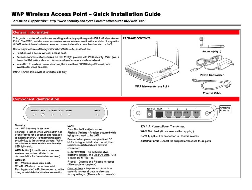
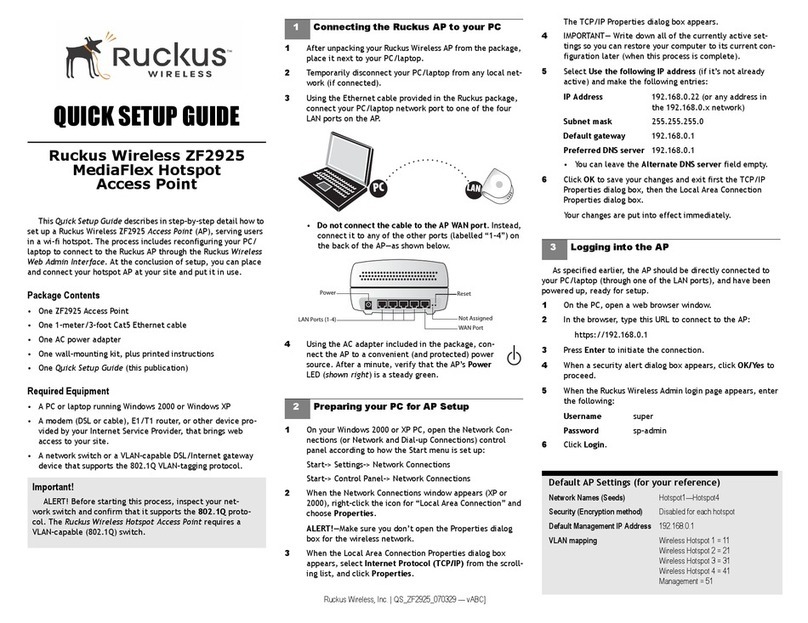
Formosa KWA-O6020-I User manual

KWA-O6020-I
Outdoor Bridge
User’s Manual

Copyright
Copyright © 2009 all rights reserved. No part of this publication may be reproduced, adapted, stored in
a retrieval system, translated into any language, or transmitted in any form or by any means without
the written permission of the supplier.
About This Manual
This user manual is intended to guide professional installer to install KWA-O6020-I and how to build
the infrastructure centered on it. It includes procedures to assist you in avoiding unforeseen problems.
Conventions
For your attention on important parts, special characters and patterns are used in this manual:
***Note:
This indicates an important note that you must pay attention to.
!!!Warning:
This indicates a warning or caution that you have to abide.
Bold: Indicates the function, important words, and so on.

FCC Statement:
Federal Communication Commission Interference Statement
This equipment has been tested and found to comply with the limits for a Class B digital device,
pursuant to Part 15 of the FCC Rules. These limits are designed to provide reasonable protection
against harmful interference in a residential installation. This equipment generates, uses and can
radiate radio frequency energy and, if not installed and used in accordance with the instructions, may
cause harmful interference to radio communications. However, there is no guarantee that interference
will not occur in a particular installation. If this equipment does cause harmful interference to radio or
television reception, which can be determined by turning the equipment off and on, the user is
encouraged to try to correct the interference by one of the following measures:
●Reorient or relocate the receiving antenna.
●Increase the separation between the equipment and receiver.
●Connect the equipment into an outlet on a circuit different from that to which the receiver is
connected.
●Consult the dealer or an experienced radio/TV technician for help.
FCC Caution: Any changes or modifications not expressly approved by the party responsible
for compliance could void the user’s authority to operate this equipment.
This device complies with Part 15 of the FCC Rules. Operation is subject to the following two
conditions: (1) This device may not cause harmful interference, and (2) this device must accept any
interference received, including interference that may cause undesired operation.
This device and its antenna(s) must not be co-located or operation in conjunction with any other
antenna or transmitter.
IMPORTANT NOTE:
FCC Radiation Exposure Statement:
This equipment complies with FCC radiation exposure limits set forth for an uncontrolled environment.
This equipment should be installed and operated with minimum distance 20cm between the radiator &
your body.

Index
Chapter 1 Introduction.............................................................................................................. 7
Introduction....................................................................................................................... 7
Appearance ....................................................................................................................... 7
Key Features ..................................................................................................................... 7
Chapter 2 Hardware Installation............................................................................................... 9
InstallationRequired......................................................................................................... 9
Safety Precautions............................................................................................................. 9
InstallationPrecautions................................................................................................... 10
Product Package.............................................................................................................. 10
Chapter 3 Basic Settings......................................................................................................... 11
Factory Default Settings ................................................................................................. 11
System Requirements...................................................................................................... 12
How to Login the Web-based Interface.......................................................................... 12
Basic System Settings..................................................................................................... 14
Time Settings.................................................................................................................. 17
RADIUS Settings............................................................................................................ 18
Basic Wireless Settings................................................................................................... 19
Site Survey...................................................................................................................... 21
Chapter 4 Advanced Settings.................................................................................................. 22
Advanced Settings .......................................................................................................... 22
Security Settings ............................................................................................................. 24
Access Control................................................................................................................ 26
WDS Settings.................................................................................................................. 27
Chapter 5 Management........................................................................................................... 28
SNMP Management........................................................................................................ 28
Configure SNMPv3 User Profile .................................................................................... 29
Password Settings ........................................................................................................... 30
Upgrade Firmware.......................................................................................................... 31
Configuration File........................................................................................................... 32
System Log ..................................................................................................................... 33
Site Survey...................................................................................................................... 34
Ping Watchdog................................................................................................................ 34
Chapter 6 Status...................................................................................................................... 35
View KWA-O6020-I Basic Information......................................................................... 35
Association List .............................................................................................................. 35
View Network Flow Statistics......................................................................................... 36

View Bridge Table.......................................................................................................... 37
View ARP Table............................................................................................................. 37
View DHCP Table.......................................................................................................... 38
Chapter 7Troubleshooting...................................................................................................... 39

Figure Index
Figure 1 KWA-O6020-I................................................................................................... 7
Figure 2 Login Page.................................................................................................... 12
Figure 3 Main Page...................................................................................................... 13
Figure 4 Basic System Settings............................................................................... 14
Figure 5 IP Settings (Bridge)..................................................................................... 15
Figure 6 IP Settings (Router)..................................................................................... 16
Figure 7 Time Settings................................................................................................ 17
Figure 8 RADIUS Settings.......................................................................................... 18
Figure 9 Basic Wireless Settings............................................................................. 19
Figure 10 Site Survey.................................................................................................. 21
Figure 11 Advanced Wireless Settings .................................................................. 22
Figure 12 Security Settings....................................................................................... 24
Figure 13 Access Control .......................................................................................... 26
Figure 14 WDS Settings ............................................................................................. 27
Figure 15 SNMP Configuration................................................................................. 28
Figure 16 Configure SNMPv3 User Profile............................................................ 29
Figure 17 Password..................................................................................................... 30
Figure 18 Upgrade Firmware..................................................................................... 31
Figure 19 Backup/Retrieve Setting.......................................................................... 32
Figure 20 System Log................................................................................................. 33
Figure 21 Site Survey.................................................................................................. 34
Figure 21 Ping Watchdog .......................................................................................... 34
Figure 22 Basic Information...................................................................................... 35
Figure 23 Connection.................................................................................................. 36
Figure 24 Network Flow Statistics........................................................................... 36
Figure 25 Bridge Table ............................................................................................... 37
Figure 26 ARP Table.................................................................................................... 38
Figure 27 DHCP Table................................................................................................. 38

Chapter 1 Introduction
Introduction
Designed for outdoor environment application, the KWA-O6020-I is a high-performance last-mile
broadband solution that provides reliable wireless network coverage. As an IEEE 802.11a/n compliant
wireless device, KWA-O6020-I is able to give stable and efficient wireless performance, while
designed with IEEE 802.11n draft 2.0 standard and high output power makes it possible to deliver
several times faster data rate then normal wireless device and higher bandwidth with longer range for
outdoor applications.
KWA-O6020-I supportsAP and Wireless Client dual wireless communication connectivity, allowing for
various application requirements thus helping to find the key to the “last mile” with least effort.
With high output power and reliable performance, KWA-O6020-I is an ideal wireless broadband
solution for wireless Internet service providers and system integrators!
Appearance
Figure 1 KWA-O6020-I
Key Features
Compliant with IEEE 802.11a and IEEE 802.11n draft 2.0 as well.
Support Power over Ethernet (PoE).
IP65 waterproof housing endures almost any harsh environments.
Dual operating modes includingAP and Wireless Client
Support 64/128-bit WEP and 802.1X, WPA, WPA2, WPA&WPA2,WPA-PSK, WPA2-PSK, and

WPA-PSK&WPA2-PSK etc
Support WMM and Quality of service (QoS) for enhanced performance
Advanced management tools like SNMP
User-friendly Web and SNMP-based management interface
Cost-effectively provide long distance backhaul for remote areas (e.g. village, oil well, island,
mountain and etc. )
Establish local backhaul for campus, farm and factory
Provide and access for video streaming or surveillance for industrial and mining enterprises

Chapter 2 Hardware Installation
Installation Required
1. Please seek assistance from a professional installer who is well trained in the RF installation and
knowledgeable in the local regulations.
2. KWA-O6020-I is distributed through distributors and system installers with professional
technicians.
Safety Precautions
1. To keep you safe and install the hardware properly, please read and follow these safety
precautions.
2. If you are installing KWA-O6020-Ifor the first time, for your safety as well as others’, please
seek assistance from a professional installer who has received safety training on the hazards
involved.
3. Keep safety as well as performance in mind when selecting your installation site, especially
where there are electric power and phone lines.
4. When installing KWA-O6020-I, please note the following things:
zDo not use a metal ladder;
zDo not work on a wet or windy day;
zWear shoes with rubber soles and heels, rubber gloves, long sleeved shirt or jacket.
5. When the system is operational, avoid standing directly in front of it. Strong RF fields are
present when the transmitter is on.

Installation Precautions
To keep KWA-O6020-I well while you are installing it, please read and follow these installation
precautions.
1.Users MUST use a proper and well-installed surge arrestor and grounding kit with
KWA-O6020-I; otherwise, a random lightening could easily cause fatal damage to
KWA-O6020-I. EMD (Lightning) DAMAGE IS NOT COVERED UNDER WARRNTY.
2.Users MUS use the “Power cord & PoE Injector” shipped in the box with KWA-O6020-I . Use
of other options will cause damage to KWA-O6020-I .
3.When you intend to use an external antenna with KWA-O6020-I, please power
KWA-O6020-Ioff first, then install the external antenna, and finally power it on for further use.
Please follow the steps as mentioned above; otherwise, damage might be caused to
KWA-O6020-I itself.
Product Package
The product package you have received should contain the following items. If any of them are not
included or damaged, please contact your local vendor for support.
zKWA-O6020-I ×1
zMounting Kit ×1
zPower Cord & PoE Injector ×1
zQuickInstallationGuide ×1
zProductCD ×1
!!!Note
zProduct CD contains Quick Installation Guide and User Manual.

Chapter 3 Basic Settings
Factory Default Settings
We’ll elaborate KWA-O6020-I factory default settings. You can re-acquire these parameters by default.
If necessary, please refer to the “Restore Factory Default Settings”
Table 1 KWA-O6020-I Factory Default Settings
Features Factor
y
Default Settin
g
s
Username admin
Password
p
assword
Wireless Device Name apXXXXXX (X represents the last 6
digits of Ethernet MAC address)
O
p
eratin
g
Mode
A
P
Da
t
a Rate
A
uto
LAN
IP
A
ddress 192.168.1.1
Subnet Mask 255.255.255.0
Gatewa
y
0.0.0.0
Primar
y
DNS Server 0.0.0.0
Secondar
y
DNS Server 0.0.0.0
S
p
annin
g
T
ree Enable
802.11 Mode 802.11a/
n
Channel Number 149
SSID Wireless
Broadcast SSID Enable
HT Protec
t
Disable
Da
t
a Rate
A
uto
Out
p
ut Power 100%
(
Full
)
Channel Mode 20MHz
WMM Disable
R
TS Threshold
(
b
y
te
)
2346
Fra
g
men
t
ation Len
g
th
(
b
y
te
)
2346
Beacon Interval 100
DTIM Interval 1
S
p
ace in Me
t
er 0
Flow Control b
y
A
P Disable
U
p
link S
p
eed Control
(
Tx
)
1687
Securit
y
O
p
en S
y
stem

Encr
y
p
tion None
Wireless Se
p
aration Disable
A
ccess Control Disable
SNMP
Enable/Disable Enable
Read Communit
y
Name Public
Write Communit
y
Name Private
IP
A
ddress 0.0.0.0
System Requirements
Before configuration, please make sure your system meets the following requirements :
- A computer coupled with 10/ 100 Base-TX adapter .
- Configure the computer with a static IP address of 192.168.1.x, as the default IP address of
KWA-O6020-I is 192.168.1.1. (X cannot be 0, 1, nor 255)
- A Web browser on PC for configuration such as Microsoft Internet Explorer 6.0 or above,
Netscape or Firefox.
How to Login the Web-based Interface
KWA-O6020-I provides you with user-friendly Web-based management tool.
Open IE and enter the IP address (Default: 192.168.1.1) of KWA-O6020-I into the address field. You
will see the login page as below.
Figure 2 Login Page
Enter the password (Default: password) and click “Login” to login the main page of KWA-O6020-I. As
you can see, this management interface provides four main options in the black bar above, which are
System, Wireless, Management and Statistics.

Figure 3 Main Page
!!!Note
zThe username and password are case-sensitive, and the password should be no more than
19 characters.

Basic System Settings
For users who use KWA-O6020-I for the first time, it is recommended that you begin configuration
from “Basic Settings” in “System” shown below :
Figure 4 Basic System Settings
Basic Settings
Network Mode: Specify the network mode, including Bridge and Router. It is easy to configure
parameters in Bridge Mode; however, users must pay extra attention to the way they configure the
device when it is set to Router Mode.
Device Name: Specify the device name for recognition, which is composed of no more than 15
characters with (0-9), (A-Z), (a-z) or (-). Device Name provides users with another option to view the
login webpage; in other words, open IE, enter the Device Name (ex: ap243943) of KWA-O6020-I into
the address field, click enter, and then login webpage will show up.
Country Region: The availability of some specific channels and/or operational frequency bands is
country dependent.
Spanning Tree: Spanning Tree Protocol (STP) is a link management protocol for AP which provides
path redundancy while preventing loops in a network. STP allows only one active path at a time
between the access points but establish the redundant link as a backup if the initial link fails.

IP Settings (Bridge)
This is available only under Bridge network mode. Open “TCP/IP Settings” in “System” as below to
configure the parameters for LAN which connects to the LAN port of KWA-O6020-I . In this page, users
may change the settings for IPAddress, Subnet Mask, and DHCP Server.
Figure 5 IP Settings (Bridge)
Obtain IP Address Automatically: If a DHCP server exists in your network, you can check this option,
thus KWA-O6020-I is able to obtain IP settings automatically from that DHCP server.
Use Fixed IP Address: Check this option. You have to specify a static IP address, subnet mask,
default gateway and DNS server for KWA-O6020-I manually. Make sure the specified IP address is
unique on your network in order to prevent IP conflict.
IP Settings (Router)
This is available only under Router mode. Open “TCP/IP Settings” in “System” as below to configure
the parameters of KWA-O6020-I for accessing the Internet.

Figure 6 IP Settings (Router)
WAN Settings: Specify the Internet access method to Static IP, DHCP or PPPOE. Users must enter
WAN IPAddress, Subnet Mask, Gateway settings provided by your ISPs.
LAN Settings: When DHCP Server is disabled, users can specify IP address and subnet mask for
KWA-O6020-I manually. Make sure the specified IP address is unique on your network in order to
prevent IP conflict. When DHCP Server is enabled, users may specify DHCP IPAddress Range,
DHCP Subnet Mask, DHCP Gateway and Lease Time (15-44640 minutes).
!!!Warning:
zIn AP mode, KWA-O6020-I must establish connection with another wireless device before it is set to
Router mode. In Router mode, it is impossible for users to access device via wired port, for WAN is on
wired port and LAN is on wireless port. Users can access device through the wireless device
connected with KWA-O6020-I .
zIn CPE mode, users can access KWA-O6020-I via its wired port, for WAN is on wireless port and LAN
is on wired port when device is set to Router mode.
zWDS mode andAP Repeater mode are similar to AP mode when device is set to Router mode; WAN
is on wired port and LAN is on wireless port. Thus users must also connect KWA-O6020-I with
another wireless device before it is set to Router mode and access KWA-O6020-I via the connected
wireless device.

Time Settings
Compliant with NTP, the KWA-O6020-I is capable of keeping its time in complete accord with the
Internet time. Make configuration in “Time Settings” from “System”. To use this feature, check
“Enable NTP Client Update” in advance.
Figure 7 Time Settings
zTime Zone Select
Select the time zone from the dropdown list.
zTime Server
Select the time server from the “NTP Server” dropdown list or manually input the IP address of
available time server into “Manual IP”.
Hit “Apply” to save settings.

RADIUS Settings
RADIUS (Remote Authentication Dial-In User Service) is a server for remote user authentication and
accounting; playing a central role in the network in providing the capabilities of authenticating,
authorizing, accounting, auditing, alarming and etc. It allows an organization to maintain user profiles
in a central database that all remote servers can share.
Open “RADIUS Settings” in “System” to make RADIUS configuration.
Figure 8 RADIUS Settings
Authentication RADIUS Server
This is for RADIUS authentication. It can communicate with RADIUS through IPAddress, Port and
Shared Secret.
IP Address: Enter the IP address of the Radius Server;
Port: Enter the port number of the Radius Server;
Shared Secret: This secret, which is composed of no more than 31 characters, is shared by the
KWA-O6020-I and RADIUS during authentication.
Re-authentication Time: Set the time interval between two authentications.
Global-Key Update: Check this option and specify the time interval between two global-key updates.

Basic Wireless Settings
Open “Basic Settings” in “Wireless” as below to make basic wireless configuration.
Figure 9 Basic Wireless Settings
Disable Wireless LAN Interface
Check this option to disable WLAN interface, then the wireless module of KWA-O6020-I will stop
working and no wireless device can connect to it.
Wireless Mode
Four operating modes are available on KWA-O6020-I.
Wireless Client: The KWA-O6020-I is able to connect to the AP and thus join the wireless network
around it.
AP: The KWA-O6020-I establishes a wireless coverage and receives connectivity from other wireless
devices.
Bridge: The KWA-O6020-I establishes wireless connectivity with other APs.
AP Repeater: The KWA-O6020-I servers asAP and Bridge at the same time. In other words, the
KWA-O6020-I can provide connectivity services for CPE’s under WDS mode.
Wireless Network Name (SSID)
This wireless network name is shared among all associated devices in your wireless network. Keep it
identical on all those devices. Note that the SSID is case-sensitive and can not exceed 32 characters.

Broadcast SSID
Under AP mode, hiding network name is necessary when you are in a wireless environment that may
have potential risk. By disabling broadcast SSID, the STA can not scan and find KWA-O6020-I, so that
malicious attack by some illegal STA could be avoided.
802.11 Mode
KWA-O6020-I can communicate with wireless devices of 802.11a or 802.11a/n. You can also select
Auto and make it work under an appropriate wireless mode automatically.
HT Protect
Enable HT (High Throughput) protect to ensure HT transmission with MAC mechanism. Under
802.11n mode, wireless client can be divided into HT STAand Non-HT STA, among which the one with
HT protect enabled gets higher throughput.
Channel Number
Channel varies much as the available band differs from country to country. Select a proper operating
channel in the drop-down list according to your situation.
Antenna
By default, KWA-O6020-I uses its built-in antenna for directional transmission; however, if you prefer to
use an external antenna for your case-dependent applications, you can switch from “ Internal ”
to ”External (RP SMA-Type)”.
!!!Note
zYou are able to choose “External (RP SMA-Type)” only when you have well done installing the
external antenna; otherwise, it might hurt KWA-O6020-I itself.
Output Power
Specify the signal transmission power. The higher the output power is, the wider the signal can cover,
but the power consumption will be greater accordingly. Usually “Full” is preferred.
Data Rate
Usually “Auto” is preferred. Under this rate, KWA-O6020-I will automatically select the highest
available rate to transmit. In some cases, however, like where there is no great demand for speed, you
can have a relatively-low transmit rate for compromise of a long distance.
Table of contents
Other Formosa Wireless Access Point manuals
Popular Wireless Access Point manuals by other brands
Luxul
Luxul XAP-1010 user guide
NETGEAR
NETGEAR SSL312 - ProSafe SSL VPN Concentrator 25 Specifications
TP-Link
TP-Link Auranet EAP320 Quick installation guide
ORiNG
ORiNG IAP-620 Series Quick installation guide
EnGenius
EnGenius M36 user manual
MikroTik
MikroTik hAP ac lite Quick setup guide and warranty information


