Forms + Surfaces HELIO BOLLARD User manual
HELIO™BOLLARD
SURFACE MOUNT WITH J-BOLTS INSTALLATION & WIRING INSTRUCTIONS
page 1 of 4 | Rev. 05-25-21
© 2021 Forms+Surfaces® | All dimensions are nominal. Specifications and pricing subject to change without notice. For the most current version of this document, please refer to our website at www.forms-surfaces.com.
T 800.451.0410 | www.forms-surfaces.com
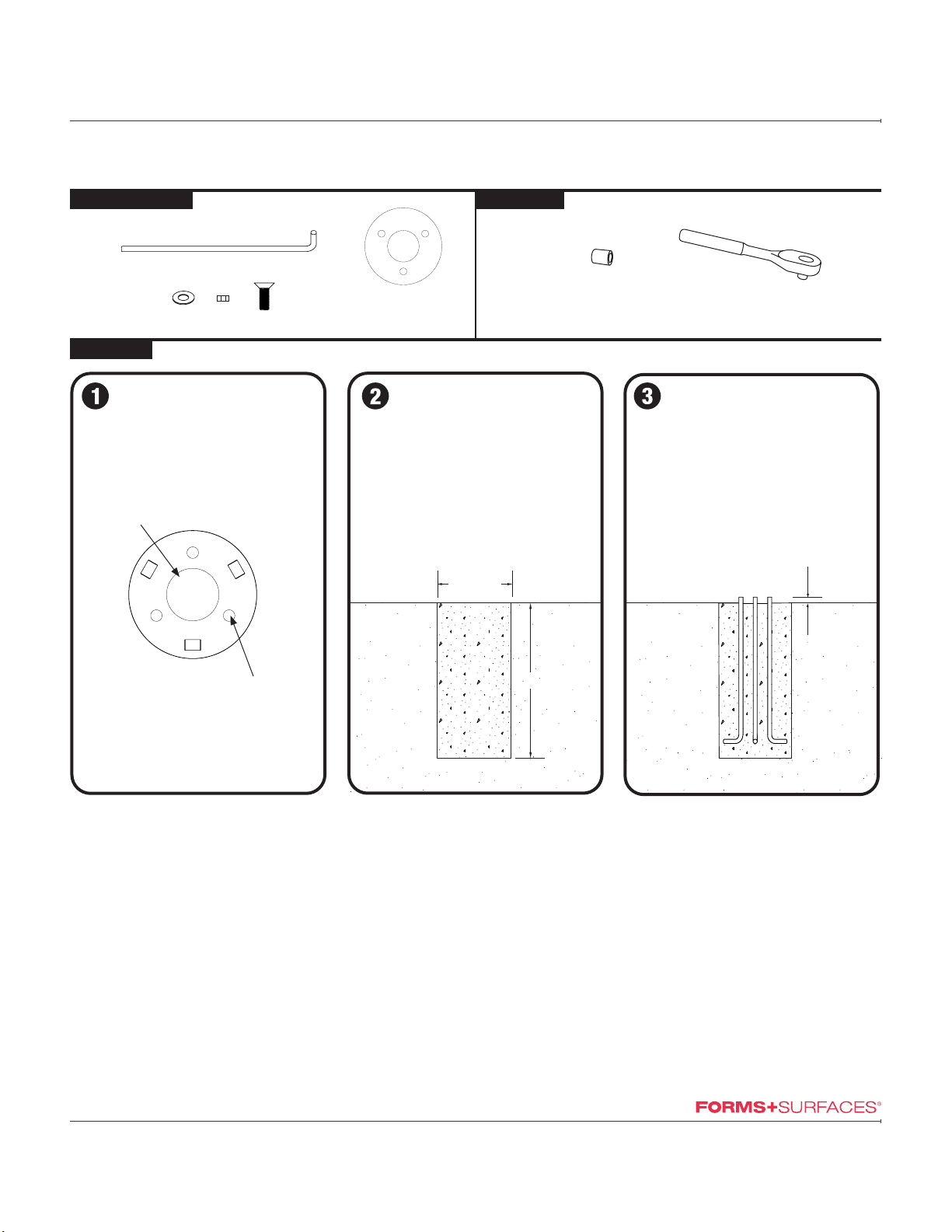
TOOLS NEEDEDMATERIALS INCLUDED
STEP BY STEP
Pour concrete footer
• Mix and pour concrete footer according
to concrete manufacturer’s instructions.
• A sufficient footer size depends on frost
and other conditions to be determined by
the installer.
• A minimum of a 13" diameter x 20"
deep footer is recommended.
Insert J-bolt anchors
• Insert 1/2"-13 x 18" galvanized steel
J-bolt anchors (a) into concrete.
• Use template to position J-bolt
anchors in proper locations. Tops of
J-bolt anchors must be a minimum of
1-1/4" above concrete surface.
• Allow concrete to set completely, in
accordance with concrete
manufacturer’s instructions, before
moving to step 3.
FOR ALL SURFACE MOUNT HELIO BOLLARDS
a
socket wrench
3/4"socket
c
b
a
template
(upon request)
a
e
d
DIAMETER a
DEPTH
1-1/4"
MINIMUM
Prepare the incoming power
• Before pouring concrete footer, run
properly sized conduit and cabling to
each luminary location according to local
code requirements. Refer to figure
above for dimensions for conduit entry
envelope size and location on luminary.
Forms+Surfaces is not responsible for
site preparation and footings.
Note: Conduit should not protrude more
than 2" above mounting surface.
Ø2.5" Conduit
Entry Location
3X Slots for
Anchor Bolts

HELIO™BOLLARD
SURFACE MOUNT WITH J-BOLTS INSTALLATION & WIRING INSTRUCTIONS
page 2 of 4 | Rev. 05-25-21
© 2021 Forms+Surfaces® | All dimensions are nominal. Specifications and pricing subject to change without notice. For the most current version of this document, please refer to our website at www.forms-surfaces.com.
T 800.451.0410 | www.forms-surfaces.com
Tighten nuts
• Use 3/4" socket and socket wrench to
tighten all nuts until snug.
STEP BY STEP FOR ALL SURFACE MOUNT HELIO BOLLARDS
Slide base onto J-bolt anchors
• Slide base base plate over J-bolt
anchors and lower base to concrete
level.
Attach base
• Slide 1/2" washer (b), then thread 1/2"-
13 nut (c) onto each J-bolt anchor.
b
c

HELIO™BOLLARD
SURFACE MOUNT WITH J-BOLTS INSTALLATION & WIRING INSTRUCTIONS
page 3 of 4 | Rev. 05-25-21
© 2021 Forms+Surfaces® | All dimensions are nominal. Specifications and pricing subject to change without notice. For the most current version of this document, please refer to our website at www.forms-surfaces.com.
T 800.451.0410 | www.forms-surfaces.com
Place bollard
• Slide bollard over base plate, lower and
align mounting holes.
STEP BY STEP FOR ALL SURFACE MOUNT HELIO BOLLARDS
Connect wires
• Insert ground (green), neutral (white), and
positive (black) wires into provided wire
nuts, being sure to match wire color
codes from junction box to bollard.
• Tighten wire nuts until exposed wire ends
are below bottom of wire nut.
• Inspect all wiring and connections before.
Caution: Light fixture rated for 120-277
VAC power.
Locate and prepare wires
Note: Installation should be performed only
by qualified individuals.
• Before proceeding with wiring of luminary,
check to ensure that all applicable site
wiring and safety codes have been
followed.
• Locate wires at base of light fixture.
• Ensure power supply is shut off and circuit
being used is isolated.
• Prepare wiring from site junction box and
bollard by stripping and removing
11-13mm (.47") of insulation.
Note: Wire used should be 22-14 AWG
copper conductors.
Caution: Installation of a surge protector as
part of each unit’s wiring is recommended.
78
11-13mm
(0.47in.)
9

HELIO™BOLLARD
SURFACE MOUNT WITH J-BOLTS INSTALLATION & WIRING INSTRUCTIONS
page 4 of 4 | Rev. 05-25-21
© 2021 Forms+Surfaces® | All dimensions are nominal. Specifications and pricing subject to change without notice. For the most current version of this document, please refer to our website at www.forms-surfaces.com.
T 800.451.0410 | www.forms-surfaces.com
Attach bollard to base plate
• Thread 5/16"-18x1" tamper-resistant
flat head screws (d) into each hole.
• Use provided T40 Torx bit for tamper-
resistant screws to tighten all screws
until snug.
STEP BY STEP FOR ALL SURFACE MOUNT HELIO BOLLARDS
dd
10
Other Forms + Surfaces Outdoor Light manuals


Popular Outdoor Light manuals by other brands


Malmbergs
Malmbergs Cupid 77 170 03 instruction manual

iGuzzini
iGuzzini TWILIGHT PROFESSIONAL manual

Trio
Trio 5111001 Series quick guide

Schrack Technik
Schrack Technik FANO Series Assembly instructions

EOI
EOI Compass Series installation instructions

Faro Barcelona
Faro Barcelona CORB 40135 quick start guide

Inspire
Inspire TRAVIS 7002102-B Assembly, Use, Maintenance Manual

Hess
Hess TOLEDO M Installation and operating instructions

LIGMAN
LIGMAN MT-31426 installation manual

Etlin-Daniels
Etlin-Daniels WP42M Series installation instructions

JONATHAN Y
JONATHAN Y JYL2049A quick start guide

JONATHAN Y
JONATHAN Y JYL6102A manual