manuals.online logo
Brands
  1. Home
  2. •
  3. Brands
  4. •
  5. Fortin
  6. •
  7. Automobile Accessories
  8. •
  9. Fortin EVO-CHR T1 User manual

Fortin EVO-CHR T1 User manual

Service No : 000 102 04 2536
EVO-CHR
Hardware Ver: 4
Firmware Ver: 2.0
Date: xx-xx
INTERFACE MODULE
Made in Canada
PATENTS PENDING US: 2007-228827-A1
www.fortinbypass.com
INSTALLATION GUIDE
Rev. I - 15 / 12 / 2009 WEB UPDATE | MISE À JOUR INTERNET
www.fortinbypass.com
Volkswagen
TECH SUPPORT
Tél: 514-255-HELP (4357)
1-877-336-7797
Fax: 514-255-1367
GUIDE INSTALLATION POUR HARNAIS EN T1 (THAR-CHR1) ET HARNAIS T2 (THAR-CHR2)
THAR-CHR1
&
THAR-CHR2
T1
INSTALLATION T1 (THAR-CHR1) ANS T-HARNESSGUIDE FOR T-HARNESS T2 (THAR-CHR2)
INTERFACE FOR REMOTE CAR STARTERS OR ALARM
INTERFACE POUR DÉMARREURS À DISTANCE OU SYSTÈMES D’ALARME
ALL
EOCHR T2
Page : 1-2-3
Page : 4-5-6
HARDWARE 4 (and higher - et plus)
FIRMWARE 2.0 (and higher - et plus)
REQUIRED \ REQUIÈRE:
Routan
VOLKSWAGEN
2004
2005
2006
2007
2008
2009
Unlock
Arm
Disarm
Trunk/Hatch
Door Trigger
Hood Trigger
Sliding door*
CHRYSLER
300-300c
Lock
Foot Brake
YEARS | ANNÉES
Hand Brake
Trunk/Hatch Trigger
Tachometer
VEHICLE FUNCTIONALITY (IF EQUIPPED)
LES FONCTIONS S’APPLIQUENT SI LE VÉHICULE EN EST ÉQUIPÉ
Charger
Town and Country
DODGE
Journey
RAM
Commander
Grand Cherokee
JEEP
Challenger
Verrouille
D/verrouille
Arme
Désarme
Valise/Hayon
Contact porte
Contact Capot
RAP Disable
Immobilizer Bypass
Start Data
AcitveRAP
Contourne Immobili.
Porte couilissante*
Frein à pied
Frein à main
Contact Valise/Hayon
Tachymetre
VEHICLE
FIT GUIDE
Grand Caravan
2010
*Sliding Door in Data-Link mode only *Porte couilissante en mode Data-Link seulement
Disconnect the ignition plug from the
ignition barrel.
Connect the male connector of the T-
Harness to the ignition barrel.
Connect the ignition plug to the female
connector of the T-Harness.
Press the EVO-CHR programming
switch while inserting the T-harness into
the EVO-CHR module.
The Red LED will illuminate to indicate
you are in programming mode, release
the programming button.
Go page 8
Débranchez le connecteur du barillet
d’ignition.
Branchez le connecteur mâle du Harnais en
T dans le barillet d’ignition.
Branchez le connecteur d’ignition dans le
connecteur femelle du Harnais en T.
Maintenez le bouton de programmation
du EVO-CHR enfoncé en insérant le
Harnais en T dans le module.
Le DEL rouge s'allume pour indiquer le
début de la programmation, relâchez le
bouton de programmation.
Continuez à la page 8
1Determine the type of remote starter
or alarm for the installation :
Installation with DATA-LINK
1-way or 2-way
with THAR-CHR1 see page 3
Installation with out DATA-LINK
with THAR-CHR1 see page 4
Déterminez le type de démarreur à
distance ou alarme pour l’installation :
Installation avec DATA-LINK
1voie ou 2 voies
avec THAR-CHR1 voir page 3
Installation sans DATA-LINK
avec THAR-CHR1 voir page 4
DATA-LINK
OR | OU
NO DATA-LINK
~
CONN. 2
23
4
5
6
EVO-CHR T1 (THAR-CHR1)
2
Pour THAR-CHR2 voir page 5For THAR-CHR2 see page 5
Make the connections on connector 2 of
the EVO-CHR. Faire les branchements du connecteur 2 du
EVO-CHR.
1
EVO-CHR T1 (THAR-CHR1)
OUTPUT | SORTIE INPUT | ENTRÉE
WITH DATA-LINK \ AVEC DATA-LINK 3
12V Battery | 12V Batterie
Lt.Blue | Bleu Pâle
White | Blanc
Pink | Rose
Blue | Bleu
Orange
Purple | Mauve
Yellow | Jaune
Trunk Status Valise
Ignition
Brake Status Frein
Tach
~
Hood Status Capot
Door Status Porte
E-Brake Status Frein Main
Lt. Blue/Black | BleuPâle/Noir
White/Black | Blanc/Noir
Pink/Black | Rose/Noir
Green | Vert
Orange/Black | Orange/Noir
Purple/White | Mauve/Blanc
Yellow/Black | Jaune/Noir
Disconnect the ignition plug from the ignition barrel.
Connect the male connector of the T-Harness to the
ignition barrel.
Connect the ignition plug to the female connector of the
T-Harness.
Press the EVO-CHR programming switch while
inserting the T-harness into the EVO-CHR module.
The Red LED will illuminate to indicate you are in
programming mode, release the programming button.
Go page 8
Débranchez le connecteur du barillet d’ignition.
Branchez le connecteur mâle du Harnais en T dans le
barillet d’ignition.
Branchez le connecteur d’ignition dans le connecteur
femelle du Harnais en T.
Maintenez le bouton de programmation du EVO-
CHR enfoncé en insérant le Harnais en T dans le
module. Le DEL rouge s'allume pour indiquer le début
de la programmation, relâchez le bouton de
programmation. Continuez à la page 8
Programming
Button Bouton de
Programmation
Parking Light | Lumière de Stationnement
Remote Starter or Alarm
Démarreur ou alarme
EVO-CHR
IGNITION BARREL
BARRILET D’IGNITION
THAR-CHR1
FEMALE
FEMELLE
MALE
MÂLE
n.c.
n.c.
1-way
1-way
1-way
1-way
1-way
1-way
1-way Only connect for 1-Way Data-Link
Branchez pour Data-Link 1-voie seulement
DATA-LINK
CONN. 2
CONN. 2
DATA C ABLE
DATA
PORT
n.c.
n.c.
n.c.
n.c.
n.c.
VEHICLE | VÉHICULE
IGNITION PLUG
CONNECTEUR
D’IGNITION
DO NOT CONNECT ON THE VEHICLE
NE PAS BRANCHEZ SUR LE VÉHICULE
346
5
3
4
5
6
3
4
5
6
OUTPUT | SORTIE INPUT | ENTRÉE
WITHOUT DATA-LINK \ SANS DATA-LINK
Lt.Blue | Bleu Pâle
White | Blanc
Pink | Rose
Blue | Bleu
Orange
Purple | Mauve
Yellow | Jaune
Trunk Status Valise
(-) While running
Lock | Verrouille
Ignition
Brake Status Frein
Tach
~
(+) Start
Hood Status Capot
Door Status Porte
E-Brake Status Frein Main
Unlock | Déverrouille
Trunk | Valise
Lt. Blue/Black | BleuPâle/Noir
White/Black | Blanc/Noir
Pink/Black | Rose/Noir
Green | Vert
Orange/Black | Org/Noir
Purple/White | Mauve/Blanc
Yellow/Black | Jaune/Noir
Programming
Button Bouton de
Programmation
Parking Light | Lumière de Stationnement
12V Battery | 12V Batterie
Ground | Masse
VEHICLE|VÉHICULE
Remote Starter or Alarm
Démarreur ou alarme
EVO-CHR
IGNITION BARREL
BARRILET D’IGNITION
THAR-CHR1
IGNITION PLUG
CONNECTEUR
D’IGNITION
FEMALE
FEMELLE
MALE
MÂLE
n.c.
n.c.
CONN. 2
CONN. 2
DO NOT CONNECT ON THE VEHICLE
NE PAS BRANCHEZ SUR LE VÉHICULE
Disconnect the ignition plug from the ignition barrel.
Connect the male connector of the T-Harness to the
ignition barrel.
Connect the ignition plug to the female connector of the
T-Harness.
Press the EVO-CHR programming switch while
inserting the T-harness into the EVO-CHR module.
The Red LED will illuminate to indicate you are in
programming mode, release the programming button.
Go page 8
Débranchez le connecteur du barillet d’ignition.
Branchez le connecteur mâle du Harnais en T dans le
barillet d’ignition.
Branchez le connecteur d’ignition dans le connecteur
femelle du Harnais en T.
Maintenez le bouton de programmation du EVO-
CHR enfoncé en insérant le Harnais en T dans le
module. Le DEL rouge s'allume pour indiquer le début
de la programmation, relâchez le bouton de
programmation. Continuez à la page 8
2
45
6
ALL
EOCHR
EVO-CHR T1 (THAR-CHR1)
4
3
4
5
6
3
4
5
6
1
Not used
Pas utilisé
3
1Determine the type remote starter or
alarm for the installation :
Installation with DATA-LINK
1-way or 2-way
with THAR-CHR2 see page 6
with THAR-CHR1 see page 4
Installation with out DATA-LINK
with THAR-CHR1 see page 5
with THAR-CHR2 see page 7
Déterminez le type de démarreur à
distance ou alarme pour l’installation :
Installation avec DATA-LINK
1voie ou 2 voies
avec THAR-CHR2 voir page 6
avec THAR-CHR1 voir page 4
Installation sans DATA-LINK
avec THAR-CHR1 voir page 5
avec THAR-CHR2 voir page 7
DATA-LINK
OR | OU
NO DATA-LINK
~
CONN. 2
2
3
4
5
6
2004
2005
2006
2007
2008
2009
2010
Unlock
Arm
Disarm
Trunk/Hatch
Door Trigger
Hood Trigger
Sliding door*
CHRYSLER
300-300c
Aspen
Crossfire
Sebring
Lock
Foot Brake
YEARS | ANNÉES
VEHICLE FUNCTIONALITY (IF EQUIPPED)
Hand Brake
Trunk/Hatch Trigger
Tachometer
LES FONCTIONS S’APPLIQUENT SI LE VÉHICULE EN EST ÉQUIPÉ
Avenger
Caliber
Charger
DODGE
Dakota
Durango
Magnum
Nitro
RAM
Commander
Compass
Grand Cherokee
Liberty
JEEP
Patriot
Wrangler
Verrouille
D/verrouille
Arme
Désarme
Valise/Hayon
Contact porte
Contact Capot
RAP Disable
Immobilizer Bypass
Start Data
AcitveRAP
Contourne Immobili.
Porte couilissante*
Frein à pied
Frein à main
Contact Valise/Hayon
Tachymetre
VEHICLE
FIT GUIDE
*Sliding Door in Data-Link mode only *Porte couilissante en mode Data-Link seulement
Disconnect the immobilizer connector
witch is located at the key cylinder.
Connect the male connector of the T-
Harness to the immobilizer module.
Connect the immobilizer connector to the
female connector of the T-Harness.
Press the EVO-CHR programming
switch while inserting the T-harness into
the EVO-CHR module.
The Red LED will illuminate to indicate
you are in programming mode, release
the programming button.
Go page 8
Débranchez le connecteur d’immobilisateur
situé au barillet de la clé.
Branchez le connecteur mâle du Harnais en
T dans le module d’immobilisation.
Branchez le connecteur d’immobilisateur
dans le connecteur femelle du Harnais en T
Maintenez le bouton de
programmation du EVO-CHR enfoncé
en insérant le Harnais en T dans le
module.
Le DEL rouge s'allume pour indiquer le
début de la programmation, relâchez le
bouton de programmation.
Continuez à la page 8
1
EVO-CHR T2 (THAR-CHR2) 5
Make the connections on connector 2 of
the EVO-CHR. Faire les branchements du connecteur 2 du
EVO-CHR.
WARNING
Connections at this connector are
only required if a Starter(+) wire is
presentontheconnector.
ATTENTION:
Les branchements à ce connecteur
sont requis seulement si il y a un fil
starter(+)présentauconnecteur.
5 PIN CONN.
Ignition plug | Connecteur d’ignition
VEHICLE | VÉHICULES
2004 - 2006
and some | et quelques
2007
Except Dodge Durango
WITH DATA-LINK
OUTPUT | SORTIE INPUT | ENTRÉE
WITH DATA-LINK \ AVEC DATA-LINK
ALL
EOCHR
EVO-CHR T2 (THAR-CHR2)
6
12V Battery | 12V Batterie
Lt.Blue | Bleu Pâle
White | Blanc
Pink | Rose
Blue | Bleu
Orange
Purple | Mauve
Yellow | Jaune
Trunk Status Valise
Brake Status Frein
Tach
~
Hood Status Capot
Door Status Porte
E-Brake Status Frein Main
Lt. Blue/Black | BleuPâle/Noir
White/Black | Blanc/Noir
Pink/Black | Rose/Noir
Green | Vert
Orange/Black | Org/Noir
Purple/White | Mauve/Blanc
Yellow/Black | Jaune/Noir
Programming
Button Bouton de
Programmation
Parking Light | Lumière de Stationnement
EVO-CHR
n.c.
1-way
1-way
1-way
1-way
1-way
1-way
CONN. 2
THAR-CHR2
FEMALE
FEMELLE
MALE
MÂLE
VEHICLE
VÉHICULE
MUX
Disconnect the immobilizer connector witch is located
at the key cylinder.
Connect the male connector of the T-Harness to the
immobilizer module.
Connect the immobilizer connector to the female
connector of the T-Harness.
Press the EVO-CHR programming switch while
inserting the T-harness into the EVO-CHR module.
The Red LED will illuminate to indicate you are in
programming mode, release the programming button.
Go page 8
Débranchez le connecteur d’immobilisateur situé au
barillet de la clé.
Branchez le connecteur mâle du Harnais en T dans le
module d’immobilisation.
Branchez le connecteur d’immobilisateur dans le
connecteur femelle du Harnais en T
Maintenez le bouton de programmation du EVO-
CHR enfoncé en insérant le Harnais en T dans le
module. Le DEL rouge s'allume pour indiquer le début
de la programmation, relâchez le bouton de
programmation. Continuez à la page 8
CONN. 2
DATA C ABLE
n.c.
n.c.
n.c.
n.c.
Remote Starter or Alarm
Démarreur ou alarme
1-way Only connect for 1-Way Data-Link
Branchez pour Data-Link 1-voie seulement
Ignition 1
12V Battery
Back view
Vue de dos
Ground
(+)
Starter
MUX
Starter (+)
PURPLE/BROWN
MAUVE/BRUN
Vehicle 2004 - 2006| Véhicules
2
1
3
4
5
6
3
4
5
6
3
4
6
5
DATA PORT
(+) Start IN
Vehicle 2004 - 2006| Véhicules
WARNING
Connections at this connector are
only required if a Starter(+) wire is
presentontheconnector.
ATTENTION:
Les branchements à ce connecteur
sont requis seulement si il y a un fil
starter(+)présentauconnecteur.
1
EVO-CHR T2 (THAR-CHR2) 7
OUTPUT | SORTIE INPUT | ENTRÉE
WITHOUT DATA-LINK \ SANS DATA-LINK
Trunk Status Valise
(-) While running
Lock | Verrouille
Ignition 1
Brake Status Frein
Tach
~
(+) Start IN
Hood Status Capot
Door Status Porte
E-Brake Status Frein Main
Unlock | Déverrouille
Trunk | Valise
Parking Light | Lumière de Stationnement
12V Battery | 12V Batterie
Ground | Masse
Remote Starter or Alarm
Démarreur ou alarme
n.c.
EVO-CHR
CONN. 2
Starter (+)
PURPLE/BROWN
MAUVE/BRUN
Programming
Button Bouton de
Programmation VEHICLE
VÉHICULE
MUX
Disconnect the immobilizer connector witch is located
at the key cylinder.
Connect the male connector of the T-Harness to the
immobilizer module.
Connect the immobilizer connector to the female
connector of the T-Harness.
Press the EVO-CHR programming switch while
inserting the T-harness into the EVO-CHR module.
The Red LED will illuminate to indicate you are in
programming mode, release the programming button.
Go page 8
Débranchez le connecteur d’immobilisateur situé au
barillet de la clé.
Branchez le connecteur d’immobilisateur dans le
connecteur Femelle du Harnais en T
Branchez le connecteur Mâle du Harnais en T dans le
module d’immobilisation.
Maintenez le bouton de programmation du EVO-
CHR enfoncé en insérant le Harnais en T dans le
module. Le DEL rouge s'allume pour indiquer le début
de la programmation, relâchez le bouton de
programmation. Continuez à la page 8
FEMALE
FEMELLE
MALE
MÂLE
THAR-CHR2
Lt.Blue | Bleu Pâle
White | Blanc
Pink | Rose
Blue | Bleu
Orange
Purple | Mauve
Yellow | Jaune
Lt. Blue/Black | BleuPâle/Noir
White/Black | Blanc/Noir
Pink/Black | Rose/Noir
Green | Vert
Orange/Black | Org/Noir
Purple/White | Mauve/Blanc
Yellow/Black | Jaune/Noir
CONN. 2
12V Battery
Back view
Vue de dos
5 PIN CONN.
Ground
(+)
Starter
Ignition plug | Connecteur d’ignition
VEHICLE | VÉHICULES
2004 - 2006
and some | et quelques
2007
Except Dodge Durango
MUX
(+) Start IN
Vehicle 2004 - 2006| Véhicules
2
1
Not used
Pas utilisé
3
4
6
5
3
4
5
6
3
4
5
6
WEB UPDATE | MISE À JOUR INTERNET
www.fortinbypass.com
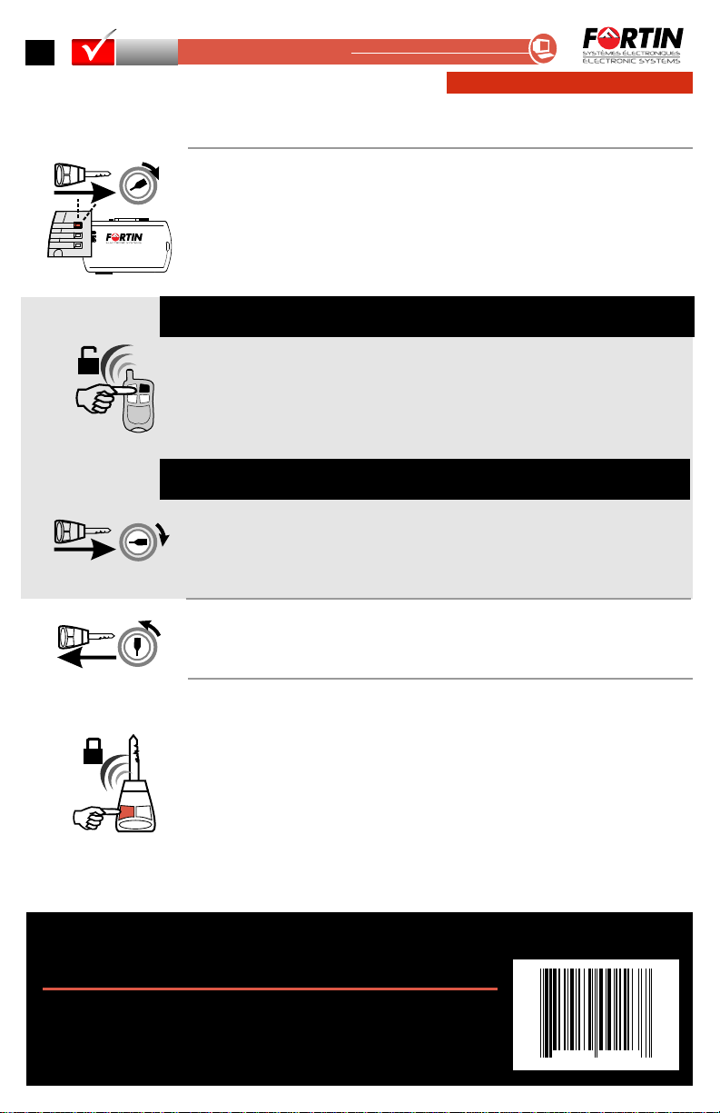
Turn the key to the "ON"
position.
PANIC
LOCK UNLOCK
The Red LED will continue to flash
until you press the lock button on
the vehicle OEM remote.
The LED will turn off to indicate the
module has been programmed.
If the vehicle is not equipped with
the OEM remote: press and release
the programming button of the EVO-
CHR module once.
The module is now ready
for use.
Turn the key to the "OFF"
position and remove the key.
7
8
IGN
START
OFF
ON
START
OFF
9
Le module est prêt à l’usage
Tournez la clé en position OFF
et retirez la clé.
Tournez la clef en position ON.
Le DEL rouge clignotera jusqu'à ce
que vous pressiez le bouton
Verrouillage (Lock) de la
télécommande d'origine du
véhicule.
Le DEL s'éteint pour indiquer que le
module est programmé.
Si le véhicule n’est pas équipé de la
télécommande d’origine: appuyez
sur le bouton de programmation du
module EVO-CHR.
La DEL rouge clignotera
rapidement
The Red LED will start to flash
rapidly
PROGRAMMING | PROGRAMMATION
Neither the manufacturer or distributor of this module is responsible of damages of any kind
indirectly or directly caused by this module, except for the replacement of this module in case of
manufacturing defects. This module must be installed by qualified technician. This install guide
maychangewithoutnotice.Visitwww.fortinbypass.comtogetlatestversion.
Ni le manufacturier, ni le distributeur ne se considèrent responsables des dommages causés ou
ayant pu être causés, indirectement ou directement, par ce module, excepté le remplacement de
ce module en cas de défectuosité de fabrication. Ce module doit être installé par un technicien
qualifié. Ce guide d'instruction peut faire l’objet de changement sans préavis. consultez le
pourvoirlaplusrécenteversion.
www.fortinbypass.com
Copyright © 2009, FORTIN AUTO RADIO INC - ALL RIGHTS RESERVED
7 770 350 00223
8ALL
EOCHR
CAUTION the module can only be programmed a maximum of 5 times on a vehicle.
ATTENTION le module peut être programmé 5 fois maximum sur un véhicule.
Start the vehicle with the key.
The LED on the EVO-CHR module
will start to flash twice as fast.
Appuyez sur le bouton
Déverrouillage de la télécommande
du démarreur à distance.
ou Mettez le fil Mauve/Blanc à la
masse à l'aide d'un fil jumper pour 1
seconde.
7b
ON
START
OFF
7C
Démarrez le véhicule avec la clé.
La DEL sur le module EVO-CHR
commence à clignoter 2 fois plus
rapidement.
Press the unlock button on the
remote car starter remote
control.
or
Put the Purple/White wire to
ground with a jumper for 1 one
second.
Véhicules équipés de
l’alarme d’origine:
Vehicles equipped with
OEM alarm:
Véhicules équipés d'un
(+) starter à l'ignition:
Vehicles equipped with
(+) starter at Ignition:
Note:Assurez-vousque lefil Bleupâle/Noir
du moduleest branchésur levéhicule.
Note:Ensure the Lt Blue/Black wire from
themodule is connected to the vehicle

This manual suits for next models

3

Other Fortin Automobile Accessories manuals

Fortin EVO-ALL User manual

Fortin

Fortin EVO-ALL User manual

Fortin EVO-ALL User manual

Fortin

Fortin EVO-ALL User manual

Fortin EVO ONE User manual

Fortin

Fortin EVO ONE User manual

Fortin EVO ONE User manual

Fortin

Fortin EVO ONE User manual

Fortin PASSLOCK-SL2 User manual

Fortin

Fortin PASSLOCK-SL2 User manual

Fortin EVO ONE THAR-ONE-HON6 User manual

Fortin

Fortin EVO ONE THAR-ONE-HON6 User manual

Fortin EVO ALL Installation and operating instructions

Fortin

Fortin EVO ALL Installation and operating instructions

Fortin EVO ONE THAR-GM7 User manual

Fortin

Fortin EVO ONE THAR-GM7 User manual

Fortin Evo One THAR-VW6 User manual

Fortin

Fortin Evo One THAR-VW6 User manual

Fortin EVO ALL User manual

Fortin

Fortin EVO ALL User manual

Fortin EVO-CAN User manual

Fortin

Fortin EVO-CAN User manual

Fortin EVO ONE User manual

Fortin

Fortin EVO ONE User manual

Fortin EVO ALL User manual

Fortin

Fortin EVO ALL User manual

Fortin EVO-CAN User manual

Fortin

Fortin EVO-CAN User manual

Fortin EVO-GMT1 User manual

Fortin

Fortin EVO-GMT1 User manual

Fortin EVO-ONE User manual

Fortin

Fortin EVO-ONE User manual

Fortin EVO ALL User manual

Fortin

Fortin EVO ALL User manual

Fortin Evo All THAR-FOR3 User manual

Fortin

Fortin Evo All THAR-FOR3 User manual

Fortin EVO ONE User manual

Fortin

Fortin EVO ONE User manual

Fortin EVO-CAN User manual

Fortin

Fortin EVO-CAN User manual

Fortin Evo One THAR-ONE-HON4 User manual

Fortin

Fortin Evo One THAR-ONE-HON4 User manual

Fortin EVO ALL User manual

Fortin

Fortin EVO ALL User manual

Fortin EVO ONE THAR-GM7 User manual

Fortin

Fortin EVO ONE THAR-GM7 User manual

Fortin EVO-ALL User manual

Fortin

Fortin EVO-ALL User manual

Popular Automobile Accessories manuals by other brands

Whispbar K655W Fitting instructions

Whispbar

Whispbar K655W Fitting instructions

Thule 1751 instructions

Thule

Thule 1751 instructions

Metra Electronics OESWC-1761-RF installation instructions

Metra Electronics

Metra Electronics OESWC-1761-RF installation instructions

Dakota Digital HDX-96J-TJ Installation

Dakota Digital

Dakota Digital HDX-96J-TJ Installation

bosal 028011 Fitting instructions

bosal

bosal 028011 Fitting instructions

MotoCrane DVM Operation manual

MotoCrane

MotoCrane DVM Operation manual

COMTRUK HD150 installation manual

COMTRUK

COMTRUK HD150 installation manual

injen technology EVO1107 installation instructions

injen technology

injen technology EVO1107 installation instructions

injen technology PF2057 installation guide

injen technology

injen technology PF2057 installation guide

Streetwize SWMAT1 quick start guide

Streetwize

Streetwize SWMAT1 quick start guide

Cruz 932-358 Assembly instructions

Cruz

Cruz 932-358 Assembly instructions

TrailFX A7059S manual

TrailFX

TrailFX A7059S manual

Fabbri RELING UNIVERSALE 116 CM instructions

Fabbri

Fabbri RELING UNIVERSALE 116 CM instructions

Shark PW026752 installation instructions

Shark

Shark PW026752 installation instructions

ECS Electronics SUZ-019-B Fitting instructions

ECS Electronics

ECS Electronics SUZ-019-B Fitting instructions

Whelen Engineering Company SA314 installation guide

Whelen Engineering Company

Whelen Engineering Company SA314 installation guide

Westfalia 57 04 08 instruction sheet

Westfalia

Westfalia 57 04 08 instruction sheet

Dynojet Power commander V installation instructions

Dynojet

Dynojet Power commander V installation instructions

manuals.online logo
manuals.online logoBrands
  • About & Mission
  • Contact us
  • Privacy Policy
  • Terms and Conditions

Copyright 2025 Manuals.Online. All Rights Reserved.