manuals.online logo
Brands
  1. Home
  2. •
  3. Brands
  4. •
  5. Fortin
  6. •
  7. Automobile Accessories
  8. •
  9. Fortin EVO ONE THAR-ONE-TOY16 User manual

Fortin EVO ONE THAR-ONE-TOY16 User manual

3.4-En-tete_QR
WARNING
ATTENTION
A11 OFF
NON
*
HOOD
PIN
HOOD STATUS : THE HOOD PIN SWITCH (INCLUDED)
MUST BE INSTALLED IF THE VEHICLE CAN BE
REMOTE STARTED WITH THE HOOD OPEN, SET FUNCTION A11 TO OFF.
CONTACT
DE CAPOT
SECURITY STICKER
AUTOCOLLANT DE
SÉCURITÉ
MANDATORY INSTALL | INSTALLATION OBLIGATOIRE Notice: the installation of safety
elements are mandatory. The hood pin
and the sticker are essential security
elements and must be installed.
Notice: l'installation des éléments de
sécurité est obligatoire. Le contact de
capot et l'autocollant de sécurité sont
des éléments de sécurité essentiels et
doivent absolument être installés.
THIS MODULE MUST BE INSTALLED BY A
QUALIFIED TECHNICIAN. A WRONG
CONNECTION CAN CAUSE PERMANENT
DAMAGE TO THE VEHICLE.
CE MODULE DOIT ÊTRE INSTALLÉ PAR
UN TECHNICIEN QUALIFIÉ, TOUTE
ERREUR DANS LES BRANCHEMENTS
PEUT OCCASIONNER DES DOMMAGES
PERMANENTS AU VÉHICULE.
STATUT DE CAPOT : LE CONTACT DE CAPOT (INCLUS), DOIT ÊTRE
INSTALLÉ SI LE VÉHICULE PEUT DÉMARRER À DISTANCE, LORSQUE LE
CAPOT EST OUVERT, PROGRAMMEZ LA FONCTION A11 À NON.
Included
Inclus
REV.: 20221019
ADDENDUM - SUGGESTED WIRING CONFIGURATION
ADDENDA - SCHÉMA DE BRANCHEMENT SUGGÉRÉ
ONE REV.: 20221019
3.4-En-tete_HOOD_MEDIUM_QR
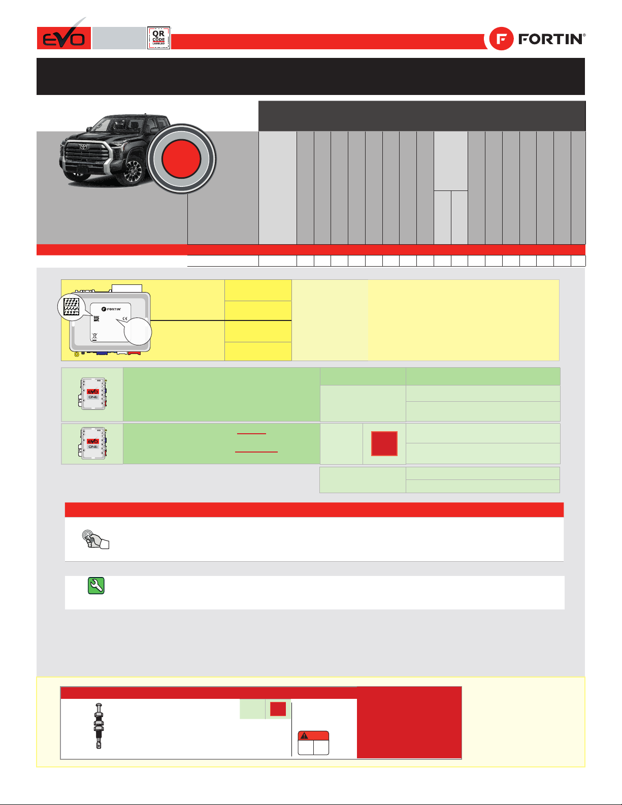
Vehicle functions supported in this diagram (functional if equipped) | Fonctions du véhicule
supportées dans ce diagramme (fonctionnelles si équipé)
VEHICLE
VEHICULES
YEARS
ANNÉES
Immobilizer bypass
Lock
Unlock
Arm
Disarm
Horn
Parking Light
Tachometer
Power Tail Gate
Comfort
Group
AUX.1
Groupe
Confort
Door Status
Trunk Status
Hand-Brake Status
Foot-Brake Status
Hood Status*
Secure Takeover
OEM Remote monitoring
Rear Defrost
Heated wiper
TOYOTA
Tundra
Push-to-Start
2022
•
•
•
•
•
•
•
•
•
•
•
•
•
•
•
•
•
•
NOTES
The vehicles OEM remote and SmartKey are
still operable during remote start.
La télécommande d’origine du véhicule et la clé intélligente reste
fonctionnel même si le démarreur est engagé.
Guide # 107631
IF THE VEHICLE IS NOT EQUIPPED
WITH FUNCTIONAL HOOD PIN:
SI LE VÉHICULE N’EST PAS ÉQUIPÉ
D’UN CONTACT DE CAPOT FONCTIONNEL: A11 OFF
NON
Hood trigger (Output Status).
Contact de capot (état de sortie).
Program bypass option:
Programmez l’option du contournement:
UNIT OPTION
OPTION UNITE DESCRIPTION
C1
OEM Remote status (Lock/Unlock)
monitoring
Suivi des status (Verrouillage/Déverrouil-
lage) de la télécommande d’origine
Parts required (Not included) Pièce(s) requise(s) (Non incluse(s))
3X 1 Amp. Diodes 3X Diodes 1 Amp.
PUSH
START
D6 Push-to-Start
Push-to-Start
MODEL: EVO-ONE
DATE:02/2019
FORTIN.CA
SN: 000000 00000
MADE IN CANADA
© 2018 ALL RIGHTS RESERVED
2019
COMPATIBLE
MODULE
REQUIRED:
QR CODE
ON THE LABEL FIRMWARE VERSION
VERSION LOGICIELLE To add the rmware version and the options, use the
FLASH LINK UPDATER or FLASH LINK MOBILE tool,
sold separately.
Pour ajouter la version logicielle et les options,
utilisez l’outil FLASH LINK UPDATER
ou FLASH LINK MOBILE, vendu séparément.
MANUFACTURED
AFTER: 2019
MODULE
COMPATIBLE
REQUIS:
CODE QR SUR
L’ÉTIQUETTE 88.[22]
FABRIQUÉ APRÈS:
2019 MINIMUM
THAR-ONE-TOY16 THARNESS INSTALLATION
INSTALLATION HARNAIS THAR-ONE-TOY16
Page 1 / 8
This guide may change without notice. See www.fortin.ca for latest version.
Ce guide peut faire l’objet de changement sans préavis. Voir www.fortin.ca pour la récente version.
DESCRIPTION |DESCRIPTION
Program remote
starter option:
Programmez l’option
démarreur à distance:
FUNCTION
FONCTION MODE DESCRIPTION
82Double 0.25 sec unlock pulse
Double pulse unlock de 0.25 sec.
34 2TRUNK OUTPUT. Pulse 2.5 Seconds.
SORTIE VALISE. Pulse 2.5 Secondes
34 3Trunk output : Unlock before trunk pulse 0.5 sec
Sortie Valise : Déverrouillage avant Valise (0.5 seconde)
38 4Enable: Alarm controled by OEM Remote.
Activé : Contrôle de l’alarme par télécommande d’origine.
14 2Alarm ON - Remote-starter ON
Alarme ON - Démarreur ON
Page 2 / 8
This guide may change without notice. See www.fortin.ca for latest version.
Ce guide peut faire l’objet de changement sans préavis. Voir www.fortin.ca pour la récente version.
DESCRIPTION |DESCRIPTION
TUNDRA
B
ECU, above driver kick panel
ECU, au dessus du panneau latéral côté conducteur
At top of drivers kick panel
Au-dessus du panneau latéral côté
conducteur
ECU, at passenger side fusebox
ECU, à la boîte à fusiles côté passager
A
3
4At Steering Column
À la colonne de direction
(-)HORN
(~) IMI (~) IMO
A
B
(-) LOCK
(-) UNLOCK
C
C
(-)POWER
LIFT GATE
Page 3 / 8
Yellow In A1
Purple Out A2
Purple/White Out A3
Green Out A4
White Out A5
Orange Out A6
Orange/Black Out A7
Dk.Blue Out A8
Red/Blue In A9
Lt.Blue/Black In/Out A10
Black In A11
Pink Out A12
Yellow/Black Out A13
Brown/White In A14
Pink/Black In A15
Purple/Yellow In/Out A16
Green/White In/Out A17
Green/Red In/Out A18
White/Black Out A19
Lt.Blue In/Out A20
C5 Brown
C4 Gray/Black
C3 Gray
C2 Orange/Brown
C1 Orange/Green
D6 White/Red
D5 White/Blue
D4 White/Green
D3 Yellow/Red
D2 Yellow/Blue
D1 Yellow/Green
White Out E1
Orange Out E2
Red In E3
Black In E4
Pink In/Out E5
Yellow Out E6
This guide may change without notice. See www.fortin.ca for latest version.
Ce guide peut faire l’objet de changement sans préavis. Voir www.fortin.ca pour la récente version.
WIRING CONNECTION | GUIDE DE BRANCHEMENTS
(-) Hood pin
HOOD PIN
CONTACT CAPOT
CUT LOOP FOR AUTOMATIC
TRANSMISSION MODE.
COUPEZ LA BOUCLE POUR LE
MODE TRANSMISSION
AUTOMATIQUE.
(-)Horn
(-)Unlock
(-)Lock
A2
A3
A4
A5
A6
A7
A8
A9
A10
A11
A12
A13
A14
A15
A16
A17
A18
A19
A20
E1
E2
E3
E4
E5
E6
C5
C4
C3
C2
C1
D6
D5
D4
D3
D2
D1
A1
D4
D5
D6
C1
C2
C5
E2
Protect the main connector
with electrical tape to prevent
shortcircuit to ground.
Protégez le connecteur
principal avec du ruban
électrique pour éviter les
cours-circuit avec la masse.
A20
A18
A17
A14
A12
A11
A9
A8
A6
A5
A4
A1
3
4
TUNDRA
1A
1C
1B
Back view - White
63-pin Connector
- located at top
of drivers kick
panel
Vue de dos -
Connecteur Blanc
de 63 pins -
au-dessus du
panneau latéral
côté conducteur.
3
23456
108
7
9 1211 1413
Steering
Column. At
switch, Black
14-Pin connector.
Colonne de
direction. Au
commutateur,
Connecteur Noir
14-pins.
4
(-)
HORN
Red
Rouge
1
10
4
5
6
7
8
9
19
20
21
17
16
14
15
13
12
18
11
23
22
1
2
3
33
27
28
29
30
31
32
43
44
45
41
40
38
39
37
35
42
34
47
46
24
25
26
55
51
52
53
54
61
62
63
59
57
58
56
36
60
48
49
50
Pink
Rose
Purple
Mauve
(~)IMO(~)IMI
CUT
Back view - Black
30-pin Connector
ECU, at passenger
side fusebox
Vue de dos -
Connecteur Noir de
30 pins
ECU, à la boîte à
fusiles côté
passager
Black
Noir
Blue
Bleu
(-)
UNLOCK
(-)
LOCK
1
10
235
678919
2021
17 16 1415 13 1218 11
27 25 24 23 2230 29 26
4
28
ECU, Above driver’s
kick panel
ECU, Au-dessus du
panneau latéral côté
conducteur
1
Back view - White 27-pin
Connector
ECU, Above driver’s
kick panel
Vue de dos - Connec-
teur Blanc de 27-pins
ECU, Au-dessus du
panneau latéral côté
conducteur
C
Pink
Rose
1
10
234
6789
1819
17 16 1415 13 12 511
23 22 21 2027 26 2425
(-)POWER
TAIL GATE
POWER TAIL GATE
(-)
T-HARNESS - HARNAIS EN T
THAR-TY120
THAR-TOY16
ISOLATE
NOT CONNECTED
---------------------
ISOLER
NON BRANCHÉ
5 PIN CONN.
LT.BLUE/BLACK - BLEU PÂLE/NOIR
PURPLE/YELLOW - MAUVE/JAUNE
YELLOW/GREEN - JAUNE/VERT
A7
YELLOW/RED - JAUNE/ROUGE
A3A2
6 PIN RED CONN.
A13
MALE T-HARNESS PLUG
CONNECTEUR MÂLE DU
T-HARNAIS
MALE VEHICLE PLUG
CONNECTEUR MÂLE DU
VÉHICULE
FEMALE T-HARNESS PLUG
CONNECTEUR FEMELLE DU
T-HARNAIS
30-pin Tan connector
Connecteur Beige de 30-pins
30-pin Tan
MALE T-HARNESS PLUG
CONNECTEUR MÂLE DU
T-HARNAIS
MALE VEHICLE PLUG
CONNECTEUR MÂLE DU
VÉHICULE
FEMALE T-HARNESS PLUG
CONNECTEUR FEMELLE DU
T-HARNAIS
30-pin White
30-pin White connector
Connecteur Blanc de 30-pins
Page 4 / 8
2
1
3
4
5
The BLUE LED will flash
rapidly.
La DEL BLEU clignotera
rapidement.
 The BLUE LED will turn ON
solide.
La DEL BLEU s'allume.
Wait, Attendez,
Appuyez sur le bouton de
démarrage deux fois pour
allumer l'ignition.
Press the Push-to-Start
button twice, to turn the
ignition ON.
 The BLUE LED will turn OFF.
 The RED LED will turn ON.
La DEL BLEU s'éteint.
La DEL ROUGE s'allume.
CONTINUED NEXT PAGE | CONTINUEZ À LA PAGE SUIVANTE
Insert the required remaining
connectors. Insérez les connecteurs
requis restants.
x2
PRESS
START
x1
PRESS
HOLD
RELEASE
START
Press the Push-to-Start
button until the engine
start.
Appuyez sur le bouton
démarrage jusqu'à se que le
moteur démarre.
Press the foot-brake pedal. Appuyez la pédale de frein.
Release the foot-brake pedal. Relâchez la pédale de frein.
x1
HOLD
between BLUE, RED,YELLOW
& BLUE/RED flashes.
un clignotement BLEU,
ROUGE, JAUNE &
 Les DELS alterneront entre The LEDs will alternate
BLEU/ROUGE
A
E
F
GJ
I
H
B
C
D
Press and hold the
programming button:
Connect the 6-PIN Main
harness (White connector).
Appuyez et maintenir le bouton
de programmation enfoncé:
Branchez le harnais Principal à
6-Pins (connecteur Blanc)
If the BLUE LED is not ON solid
disconnect the 6-Pin Main
connector and go back to step 1.
Si la DEL BLEUE n'est pas
allumée débranchez le
connecteur Principal à
6-broches et retournez au
début de l'étape 1.
RELEASE
A
E
F
GJ
I
H
B
C
D
ON BLUE
BLEU
A
E
F
G
J
I
H
B
C
D
Release the programming
button when the LED is BLUE. Relâchez le bouton de
programmation quand la DEL
est BLEU.
A
E
F
G
J
I
H
B
C
D
A
E
F
GJ
I
H
B
C
D
A
E
F
G
J
I
H
B
C
D
A
E
F
G
J
I
H
B
C
D
A
E
F
GJ
I
H
B
C
D
A
E
F
GJ
I
H
B
C
D
WAIT
ON
ON
IGNITION OFF IGNITION ON
FLASH
RAPIDLY
STARTIGNI.
ON OFF
ON
This guide may change without notice. See www.fortin.ca for latest version.
Ce guide peut faire l’objet de changement sans préavis. Voir www.fortin.ca pour la récente version.
DCRYPTOR PROGRAMMING PROCEDURE |PROCÉDURE DE PROGRAMMATION AVEC DCRYPTOR
Parts required (not included) Pièces requises (non incluses)
1x FLASH LINK UPDATER,
1x FLASH LINK MANAGER
1x FLASH LINK MOBILE
1x FLASH LINK MOBILE APP
SOFTWARE | PROGRAMME
Smartphone Android or iOS with Internet connection
(Internet provider charges may apply)
Téléphone Intelligent Android ou iOS avec connection
Internet (des frais du fournisseur Internet peuvent s’appliquer)
OR
OU
Microsoft Windows Computer with Internet connection
Ordinateur Microsoft Windows avec connection Internet
1x1x
BEFORE PROGRAMMING SET THE UNIT OPTIONS AND SAVE. | AVANT LA PROGRAMMATION CONFIGURER LES OPTIONS DE L'UNITÉ ET SAUVEGARDER.
5-Prog.1-17-SPECIAL1_PTS
Page 5 / 8
Wait, Attendez,
 The RED LED will turn OFF.
 The YELLOW LED will turn ON.
La DEL ROUGE s'éteint.
La DEL JAUNE s'allume.
The RED and YELLOW LEDs
will alternate.
La DEL ROUGE et JAUNE
alternent.
OFF
x1
PRESS
OFF
x1
PRESS
Press the Push-to-Start
button once to turn off the
engine.
Appuyez sur le bouton
démarrage une fois pour
éteindre le moteur.
Press the Push-to-Start
button once to turn off the
engine.
Appuyez sur le bouton
démarrage une fois pour
éteindre le moteur.
7
8
6
Press the Push-to-Start
button until the engine
start.
Appuyez sur le bouton
démarrage jusqu'à se que le
moteur démarre.
Press the foot-brake pedal. Appuyez la pédale de frein.
Release the foot-brake pedal. Relâchez la pédale de frein.
START
x1
PRESS
HOLD
RELEASE
START
A
E
F
GJ
I
H
B
C
D
WAIT
STARTOFF
ON OFF
ON
FLASH RAPIDLY
A
E
F
GJ
I
H
B
C
D
A
E
F
G
J
I
H
B
C
D
A
E
F
G
J
I
H
B
C
D
A
E
F
GJ
I
H
B
C
D
A
E
F
G
J
I
H
B
C
D
A
E
F
G
J
I
H
B
C
D
A
E
F
G
J
I
H
B
C
D
A
E
F
GJ
I
H
B
C
D
A
E
F
G
J
I
H
B
C
D
A
E
F
GJ
I
H
B
C
D
Disconnect all connectors and after the 6-Pin (Main-Harness)
or the 4-Pin Data-link connector.
Débranchez tous les connecteurs et ensuite le connecteur
6-pins (Connecteur principal) ou le connecteur
4-pins (Data-Link).
REMOTE STARTER / ALARM VERIFICATION
PROCEDURE | PROCÉDURE DE VÉRIFICATION
DU DÉMARREUR À DISTANCE / ALARME
The module is now programmed.
Le module est programmé. Test the remote starter. Remote start the vehicle.
Testez le démarreur à distance. Démarrez le véhicule
à distance.
AFTER DCRYPTOR PROGRAMMING COMPLETED
Go back to the vehicle and reconnect the 6-Pin (Main-
Harness) or the 4-pins (Data-Link) connector
and after all the remaining connector.
APRÈS LA PROCÉDURE DE PROGRAMMATION
DCRYPTOR COMPLETÉE : retournez au véhicule et
rebranchez le connecteur 6-pins (Connecteur principal)
ou le 4-pins (Data-Link) et après tous les connecteurs.
FLASH LINK UPDATER*
FLASH LINK MOBILE*
FLASH LINK MANAGER*
SOFTWARE | PROGRAMME
A
E
F
GJ
I
H
B
C
D
A
E
F
GJ
I
H
B
C
D
Microsoft Windows
Computer with
Internet connection*
Ordinateur Microsoft
Windows avec
connection Internet*
*Pièces requises (non incluses)
Use the tool:
FLASH LINK UPDATER or
FLASH LINK MOBILE
to visit the DCryptor menu.
Utilisez l'outil:
FLASH LINK UPDATER ou
FLASH LINK MOBILE
pour visiter le menu DCryptor.
*Parts required (not included)
VEHICLE'S OBDII
CONNECTOR
CONNECTEUR OBDII
DU VÉHICULE
OR
OU Smartphone*
(Internet provider
charges
may apply)
Téléphone
Intelligent*
(des frais du
fournisseur
Internet peuvent
s’appliquer)
9
10
11
This guide may change without notice. See www.fortin.ca for latest version.
Ce guide peut faire l’objet de changement sans préavis. Voir www.fortin.ca pour la récente version.
KEY BYPASS PROGRAMMING PROCEDURE 2/2 |PROCÉDURE DE PROGRAMMATION CONTOURNEMENT DE CLÉ 2/2
5-Prog.1-17-SPECIAL2_PTS
Page 6 / 8
Remote start the
vehicle.
Démarrez à
distance.
All doors must
be closed.
Toutes les
portes doivent
être fermées
Press the brake pedal.
The vehicle can now be
put in to gear and
driven.
If the Smart-Key is not detected
the vehicle will shut down.
Appuyez sur la pédale de
frein.
Vous êtes maintenant
prêt à embrayer et
prendre la route.
Si la clé intelligente n'est pas
détectées le véhicule s'éteindra.
ON
x1
PRESS
DO NOT PRESS THE
BRAKE PEDAL.
Press and release
the Push-to-Start
button once.
NE PAS APPUYER LA
PÉDALE DE FREIN.
Appuyez et relâchez
une fois le bouton
démarrage
(Push-to-Start.
Start
Enter the vehicle with the
SMART-KEY.
Entrez dans le véhicule
avec la clé intelligente
(SMART-Key) sur vous
UNLOCK
Unlock the doors with
either:
• The OEM remote
• The remote-starter
remote
• Or the proximity remote
Déverrouillez les portes
avec soit:
• la télécommande
d'origine
• la télécomande du
démarreur à distance
• ou la télécommande de
proximté.
This guide may change without notice. See www.fortin.ca for latest version.
Ce guide peut faire l’objet de changement sans préavis. Voir www.fortin.ca pour la récente version.
REMOTE STARTER PROGRAMMING PROCEDURE |PROCÉDURE DE PROGRAMMATION DU DÉMARREUR À DISTANCE
REFER TO THE QUICK INSTALL GUIDE INCLUDED WITH THE
MODULE FOR THE REMOTE STARTER PROGRAMMING.
RÉFÉREZ-VOUS AU GUIDE D’INSTALLATION RAPIDE INCLUS
AVEC LE MODULE POUR LA PROGRAMMATION DU DÉMARREUR
À DISTANCE.
REMOTE STARTER FUNCTIONALITY |FONCTIONNALITÉS DU DÉMARREUR À DISTANCE
Page 7 / 8
FIN-DISCLAIMER_QR
Module label | Étiquette sur le module
Notice: Updated Firmware and Installation Guides
Updated fi rmware and installation guides are posted on our web site on a regular
basis. We recommend that you update this module to the latest firmware and
download the latest installation guide(s) prior to the installation of this product.
Notice: Mise à jour microprogramme et Guides d’installations
Des mises à jour du Firmware (microprogramme) et des guides d’installation
sont mis en ligne régulièrement. Vérifiez que vous avez bien la dernière version
logiciel et le dernier guide d’installation avant l’installation de ce produit.
WARNING
The information on this sheet is provided on an (as is) basis with no representation or warranty of accuracy whatsoever.
It is the sole responsibility of the installer to check and verify any circuit before connecting to it. Only a computer safe
logic probe or digital multimeter should be used. FORTIN ELECTRONIC SYSTEMS assumes absolutely no liability or
responsibility whatsoever pertaining to the accuracy or currency of the information supplied. The installation in every case
is the sole responsibility of the installer performing the work and FORTIN ELECTRONIC SYSTEMS assumes no liability
or responsibility whatsoever resulting from any type of installation, whether performed properly, improperly or any other
way. Neither the manufacturer or distributor of this module is responsible of damages of any kind indirectly or directly
caused by this module, except for the replacement of this module in case of manufacturing defects. This module must be
installed by qualified technician. The information supplied is a guide only. This instruction guide may change without
notice. Visit www.fortinbypass.com to get the latest version.
MISE EN GARDE
L’information de ce guide est fournie sur la base de représentation (telle quelle) sans aucune garantie de précision et
d’exactitude. Il est de la seule responsabilité de l’installateur de vérifier tous les fils et circuits avant d’effectuer les connexions.
Seuls une sonde logique ou un multimètre digital doivent être utilisés. FORTIN SYSTÈMES ÉLECTRONIQUES n’assume
aucune responsabilité de l’exactitude de l’information fournie. L’installation (dans chaque cas) est la responsabilité de
l’installateur effectuant le travail. FORTIN SYSTÈMES ÉLECTRONIQUES n’assume aucune responsabilité suite à
l’installation, que celle-ci soit bonne, mauvaise ou de n’importe autre type. Ni le manufacturier, ni le distributeur ne se
considèrent responsables des dommages causés ou ayant pu être causés, indirectement ou directement, par ce module,
excepté le remplacement de ce module en cas de défectuosité de fabrication. Ce module doit être installé par un technicien
qualifié. L’information fournie dans ce guide est une suggestion. Ce guide d’instruction peut faire l’objet de changement
sans préavis. Consultez le www.fortinbypass.com pour voir la plus récente version.
Copyright © 2006-2019, FORTIN AUTO RADIO INC ALL RIGHTS RESERVED PATENT PENDING
TECH SUPPORT
Tél: 514-255-HELP (4357)
1-877-336-7797
ADDENDUM GUIDE WEB UPDATE | MISE À JOUR INTERNET
www.fortinbypass.com
ONE
MODEL: EVO-ONE
DATE:02/2019
FORTIN.CA
SN: 000000 00000
MADE IN CANADA
© 2018 ALL RIGHTS RESERVED
Page 8 / 8

Other Fortin Automobile Accessories manuals

Fortin EVO ALL User manual

Fortin

Fortin EVO ALL User manual

Fortin Evo ONE THAR-ONE-TOY1 User manual

Fortin

Fortin Evo ONE THAR-ONE-TOY1 User manual

Fortin PATS 1 User manual

Fortin

Fortin PATS 1 User manual

Fortin KEY-OVERRIDE-SL2 User manual

Fortin

Fortin KEY-OVERRIDE-SL2 User manual

Fortin EVO-ONE User manual

Fortin

Fortin EVO-ONE User manual

Fortin THAR-AUD1 User manual

Fortin

Fortin THAR-AUD1 User manual

Fortin PATS-GM User manual

Fortin

Fortin PATS-GM User manual

Fortin EVO-CHR T1 User manual

Fortin

Fortin EVO-CHR T1 User manual

Fortin EVO ONE User manual

Fortin

Fortin EVO ONE User manual

Fortin Evo All THAR-CHR4 User manual

Fortin

Fortin Evo All THAR-CHR4 User manual

Fortin EVO KEY User manual

Fortin

Fortin EVO KEY User manual

Fortin EVO ALL User manual

Fortin

Fortin EVO ALL User manual

Fortin Evo One THAR-ONE-HON4 User manual

Fortin

Fortin Evo One THAR-ONE-HON4 User manual

Fortin EVO ONE THAR-GM7 User manual

Fortin

Fortin EVO ONE THAR-GM7 User manual

Fortin EVO-ONE User manual

Fortin

Fortin EVO-ONE User manual

Fortin EVO-ALL User manual

Fortin

Fortin EVO-ALL User manual

Fortin EVO KEY User manual

Fortin

Fortin EVO KEY User manual

Fortin Evo One THAR-ONE-TOY1 User manual

Fortin

Fortin Evo One THAR-ONE-TOY1 User manual

Fortin EVO ONE THAR-GM7 User manual

Fortin

Fortin EVO ONE THAR-GM7 User manual

Fortin EVO ONE User manual

Fortin

Fortin EVO ONE User manual

Fortin INT-SL User manual

Fortin

Fortin INT-SL User manual

Fortin EVO ALL Installation and operating instructions

Fortin

Fortin EVO ALL Installation and operating instructions

Fortin EVO ALL User manual

Fortin

Fortin EVO ALL User manual

Fortin EVO ONE User manual

Fortin

Fortin EVO ONE User manual

Popular Automobile Accessories manuals by other brands

Axxess AXDSPL-NI1 installation instructions

Axxess

Axxess AXDSPL-NI1 installation instructions

Steinhof S-017 FITTING AND OPERATION MANUAL

Steinhof

Steinhof S-017 FITTING AND OPERATION MANUAL

EchoMaster Pro FCTP-MB1903 installation guide

EchoMaster Pro

EchoMaster Pro FCTP-MB1903 installation guide

Metra Electronics 99-7388HG installation instructions

Metra Electronics

Metra Electronics 99-7388HG installation instructions

Cobra Fi2000 instruction manual

Cobra

Cobra Fi2000 instruction manual

Surco Products J400 instructions

Surco Products

Surco Products J400 instructions

Neuspeed 25.02.22.2 installation instructions

Neuspeed

Neuspeed 25.02.22.2 installation instructions

WallboxOK EV PORTABLE TYPE1 User and installation guide

WallboxOK

WallboxOK EV PORTABLE TYPE1 User and installation guide

Tellur TLL151261 user manual

Tellur

Tellur TLL151261 user manual

Witter F177U Fitting instructions

Witter

Witter F177U Fitting instructions

Seat Dataplug Operating and installation instructions

Seat

Seat Dataplug Operating and installation instructions

Winmate FM10A user manual

Winmate

Winmate FM10A user manual

Paroli ProCar 251050000100 manual

Paroli

Paroli ProCar 251050000100 manual

Thule 145116 quick start guide

Thule

Thule 145116 quick start guide

GT MAX NR-8522 user manual

GT MAX

GT MAX NR-8522 user manual

TypePal TA22X user manual

TypePal

TypePal TA22X user manual

Feniex FUSION-S FS-8816 instruction manual

Feniex

Feniex FUSION-S FS-8816 instruction manual

Metra Electronics 95-7510 installation instructions

Metra Electronics

Metra Electronics 95-7510 installation instructions

manuals.online logo
manuals.online logoBrands
  • About & Mission
  • Contact us
  • Privacy Policy
  • Terms and Conditions

Copyright 2025 Manuals.Online. All Rights Reserved.