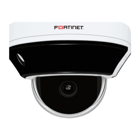
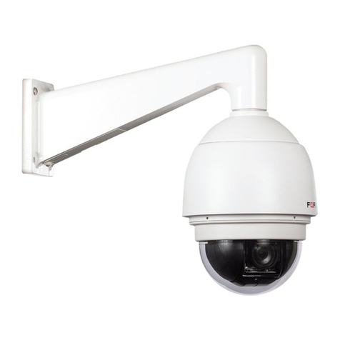
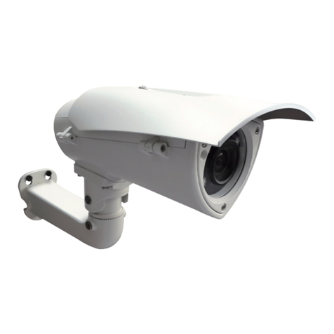
Fortinet FortiCam FE120B User manual

FortiCam FE120B
QuickStart Guide

December 14, 2022
1st Edition
Copyright © 2022 Fortinet, Inc. All rights reserved. Fortinet®, FortiGate®, FortiCare®and FortiGuard®,
and certain other marks are registered trademarks of Fortinet, Inc., and other Fortinet names herein
may also be registered and/or common law trademarks of Fortinet. All other product or company
names may be trademarks of their respective owners. Performance and other metrics contained
herein were attained in internal lab tests under ideal conditions, and actual performance and
other results may vary. Network variables, dierent network environments and other conditions
may aect performance results. Nothing herein represents any binding commitment by Fortinet,
and Fortinet disclaims all warranties, whether express or implied, except to the extent Fortinet
enters a binding written contract, signed by Fortinet’s General Counsel, with a purchaser that
expressly warrants that the identied product will perform according to certain expressly-
identied performance metrics and, in such event, only the specic performance metrics expressly
identied in such binding written contract shall be binding on Fortinet. For absolute clarity, any
such warranty will be limited to performance in the same ideal conditions as in Fortinet’s internal
lab tests. Fortinet disclaims in full any covenants, representations, and guarantees pursuant hereto,
whether express or implied. Fortinet reserves the right to change, modify, transfer, or otherwise
revise this publication without notice, and the most current version of the publication shall be
applicable.
Technical Documentation http://docs.fortinet.com
Knowledge Base http://kb.fortinet.com
Forums https://forum.fortinet.com
Customer Service & Support https://support.fortinet.com
Training Services http://training.fortinet.com
FortiGuard Threat Research & Response http://www.fortiguard.com
For Product License Agreement/EULA and Warranty Terms, visit:
https://www.fortinet.com/content/dam/fortinet/assets/legal/EULA.pdf
Package Contents 4
Hardware Overview 5
Hardware Installation 6
Camera Connection 12
Technical Specications 13
Register for Support 15
Regulatory Notices 16
Cautions and Warnings 17
Table of Contents

Page 4
Package Contents
• 1x FortiCamera
• 1x torx screwdriver
• 1x alignment sticker
• 4x screws and 4x screw anchors
• 1x waterproof grommet and Ethernet connector push tip
• 1x replacement dry pack

Page 5
Hardware Overview
The FortiCam FE120B supports a variety of junction boxes:
Junction Boxes
A Pendant cap FCM-FE120B-PCP
2 14-11/16 square gang box
3 4” square and round box
4 4” octagon box
5 1” single gang box
6 Cantex ¾”type FSE 2 Gang

Page 6
Hardware Installation
Caution:Caution: Adequate grounding must be provided to the unit and the PoE
injector, in compliance with your local electrical code or regulations.
Note:Note: Avoid exposure to direct sunlight for outdoor installation for better
image quality and longer service life.
Important:Important: Only remove the protective wrap from the camera lens when the
entire installation process is completed to avoid damage.
To install the cameraTo install the camera
1. Loosen the four screws with the included torx screwdriver to remove
the camera’s cover.
2. Position the alignment sticker on the desired mounting surface and drill
holes for the four mounting screws and a hole for the cable.

Page 7
3. Press the tabs on the side of the camera to separate the camera from
the mounting plate.
4. Mount the mounting plate using the included screws and plugs.

Page 8
5. Open the small hole in the grommet by pulling o the center tip.
6. Remove the protective cap from the Ethernet cable and use the
Ethernet connector push tip to push the Ethernet cable through the
grommet, making sure the grommet membrane is folded outwards.

Page 9
7. Fit the grommet tightly into the camera body and connect the network
cable.
8. Replace the desiccant bag.

Page 10
9. Snap the camera onto the mounting plate.
10. Attach the camera’s cover and then fasten with the four provided
screws.

Page 11
11. Remove the protective covering from the lens after installation.
For more mounting options, such as pendant cap mounting for the
FCM-FE120B-PCP, see the FE120B Mounting Guide.

Page 12
Camera Connection
Caution:Caution: This device complies with IEEE 802.3at PoE specication. Do not use
any PoE injectors that are not IEEE 802.3at compliant as they may damage
your device.
1 2 3 4
CONSOLE
USB
USB
FortiRecorder200D
FortiRecorderPoE Switch
Camera
To connect the cameraTo connect the camera
1. Connect the camera’s Ethernet port to the FortiRecorder NVR via a
PoE switch. The camera gets its IP address from the DHCP server
automatically.
2. Go to the FortiRecorder web UI to congure the discovered
camera. For details, see the FortiRecorder Administration Guide on
http://docs.fortinet.com.
To reset the camera to factory defaultTo reset the camera to factory default
1. Remove the camera cover.
2. Press and hold the Reset button for more than 5 seconds.
NoteNote: The camera’s default IP address is 192.168.1.245.

Page 13
Technical Specications
Camera
Format Fisheye, Indoor/Outdoor, Vandal
Sensor Type 12 Megapixel, 1/2.3”Progressive CMOS
Iris F2.0, Fixed
Focal Length f = 1.22mm
View Angle Ceiling Mount: 360°; Wall Mount: 180°; Table Mount:
360°
Minimum Illumination 0.01 Lux (Color)@F1.4, 0.005 Lux (B/W)@F2
Wide Dynamic Range Shutter WDR (>120dB)
Network Interface RJ-45 Ethernet 10/100/1000Mbps
IRLED/IRC 20+m/Yes
EIS/DNR -/3DNR
Streaming Protocol RTSP
SD Card Micro SD/SDHC/SDXC, up to 512G/1TB (not included)
Audio One-way, built-in microphone
Video Compression H.264/H.265 (HEVC)

Page 14
Image Resolution 30fps @ 2944x2944 (WDR o )
20fps @ 2944x2944 (WDR on)
1920x1920 1024x1024
Local dewarp:
Wall 30fps@ 2048x768 1280x480
Ceiling/table 30fps@ 2944x736 1920x480
Mounting Wall, Ceiling, Table, Pole, Drop tube, Junction box
Dimensions
Height x Width x Length 2.7 x 5.9 x 5.9’’(68 x 150 x 150 mm)
Weight 1.55lb (701g)
Environment
Power Required PoE (802.3at) Class 4
Power Consumption
(AVG)
9.55 W, 22.5 W max (with IR on)
Operating Temperature Starting: -4°F ~ 122°F (-20°C ~ 50°C)
Working IR OFF: -40°F ~ 131°F (-40°C ~ 55°C)
Working IR ON: -40°F ~ 122°F (-40°C ~ 50°C)
Humidity 0-90% Non-condensing
Compliance
FCC Part 15B Class A, ICES-003 Class A, CE (EN 55032 Class A, EN 55035), CB (IEC/
EN 62368-1, IEC/EN 60950-22), IP66, IK10, ONVIF Prole G, S, T

Page 15
Register for Support
Register your Fortinet product to receive:
• Technical support • New product features • Protection from new threats
Vous devez enregistrer le produit pour recevoir:
• Support technique • Nouvelles fonctionnalitées du produit • Protection contre de nouvelles menaces
La reistrazione ti permette di usufruire di:
• Supporto tecnico • Nuove funzionalita • Proteezione dalle ultime minaccce
Debe registrar el producto para recibir:
• Apoyo técnico • Nuevas funcionalidades del producto • Protección contra ataques
下記フォーティネットからのサービスを受けるために、ご購入製品の登録が必要です:
• テクニカルサポート • 新機能の追加 • 新しい脅威への防御
注册您的飞塔产品后可以得到:
• 技术支持 • 新产品特点信息 • 最新威胁防护
Web: https://support.fortinet.com/
Toll free: 1 866 648 4638
Phone: 1 408 486 7899
Fax: 1 408 235 7737
Email: [email protected]

Page 16
Regulatory Notices
Federal Communication Commission (FCC) – USA
This device complies with Part 15 of FCC Rules. Operation is subject to the following two conditions:
(1) this device may not cause harmful interference, and
(2) this device must accept any interference received; including interference that may cause undesired operation.
This equipment has been tested and found to comply with the limits for a Class A digital device, pursuant to Part 15 of the FCC Rules.
These limits are designed to provide reasonable protection against harmful interference when the equipment is operated in a commercial
environment. This equipment generates, uses, and can radiate radio frequency energy, and if it is not installed and used in accordance with
the instruction manual, it may cause harmful interference to radio communications. Operation of this equipment in a residential area is likely
to cause harmful interference, in which case the user will be required to correct the interference at his own expense.
WARNING: Any changes or modications to this product not expressly approved by the party responsible for compliance could void the
user’s authority to operate the equipment
Industry Canada Equipment Standard for Digital Equipment (ICES) – Canada
CAN ICES-003 (A) / NMB-003 (A)
This digital apparatus does not exceed the Class A limits for radio noise emissions from digital apparatus set out in the Radio Interference
Regula¬tions of the Canadian Department of Communications.
Cet appareil numérique n’émet pas de bruits radioélectriques dépassant les limites applicables aux appareils numériques de la classe A
prescrites dans le Règlement sur le brouillage radioélectrique édicte par le ministère des Communications du Canada.
European Conformity (CE) - EU
This is a Class A product. In a domestic environment, this product may cause radio interference, in which case the user may be required to
take adequate measures.

Page 17
Cautions and Warnings
Environmental Specications
Refer to specic Product Model Data Sheet for Environmental Specications (Operating Temperature, Storage Temperature, Humidity, and
Altitude).
Référez à la Fiche Technique de ce produit pour les caractéristiques environnementales (Température de fonctionnement, température de
stockage, humidité et l’altitude).
Safety
Caution: This equipment is to be used in a Network Environment 0 per IECTR 62101. This product is connected only to PoE networks without
routing to the outside plant.
Attention: Ce matériel doit être utilisé dans un Environnement Réseau 0 par IECTR 62101. Ce produit est uniquement connecté aux réseaux
PoE sans installation externe de routage.
This product is intended to be supplied by a Listed Direct Plug-In Power Unit marked LPS or Class 2 and rated 12 Vdc, 1.75 A or by 37-57
Vdc from PoE source.
Le produit doit être alimenté par un bloc d’alimentation à courant continu homologué UL de 12 Vdc, 1.75 A nominal marqué LPS ou Class 2
ou par une source d’alimentation par Ethernet de 37-57 Vdc (PoE).
The connecting cable between the outdoor equipment and the indoor ITE devices should comply with Class 3 wiring methods as listed in
NEC, Table 725.154(G) for Class 3 Cable Substitutions.
Le câble connectant l’équipement extérieur et ceux d’intérieur de type ITE doit être conforme avec les méthodes de câblage de classe 3 tel
que listé dans le standard NEC, Table 725.154(G) pour les câbles de substitutions de classe 3.
PoE input cable type should be CL3, CL3P, CL3R, CL3X, marked “SUNLIGHT RESISTANT”, “SUN. RES.”, or “SR.”and“water resistant”or“W”.
Le type de câble PoE d’entrée doit être CL3, CL3P, CL3R, CL3X marqué “SUNLIGHT RESISTANT”. “SUN RES.» Ou «SR». et “waterproof” ou “W”.
Note: Avoid direct sunlight for outdoor installations for better image quality and longer service life.

Other manuals for FortiCam FE120B
1
Table of contents
Other Fortinet Security Camera manuals

Fortinet
Fortinet FortiCam MD40 Installation instructions manual

Fortinet
Fortinet FortiCam SD20 Installation instructions manual

Fortinet
Fortinet FortiCam MC51-C User manual

Fortinet
Fortinet FortiCam FD55-CA User manual

Fortinet
Fortinet FortiCam SD20B Installation instructions manual

Fortinet
Fortinet FortiCam PD50 User manual

Fortinet
Fortinet FortiCam MC51 User manual

Fortinet
Fortinet FortiGate Rugged 60D User manual

Fortinet
Fortinet FortiMail-400C User manual

Fortinet
Fortinet FortiCam CD51 Installation instructions manual