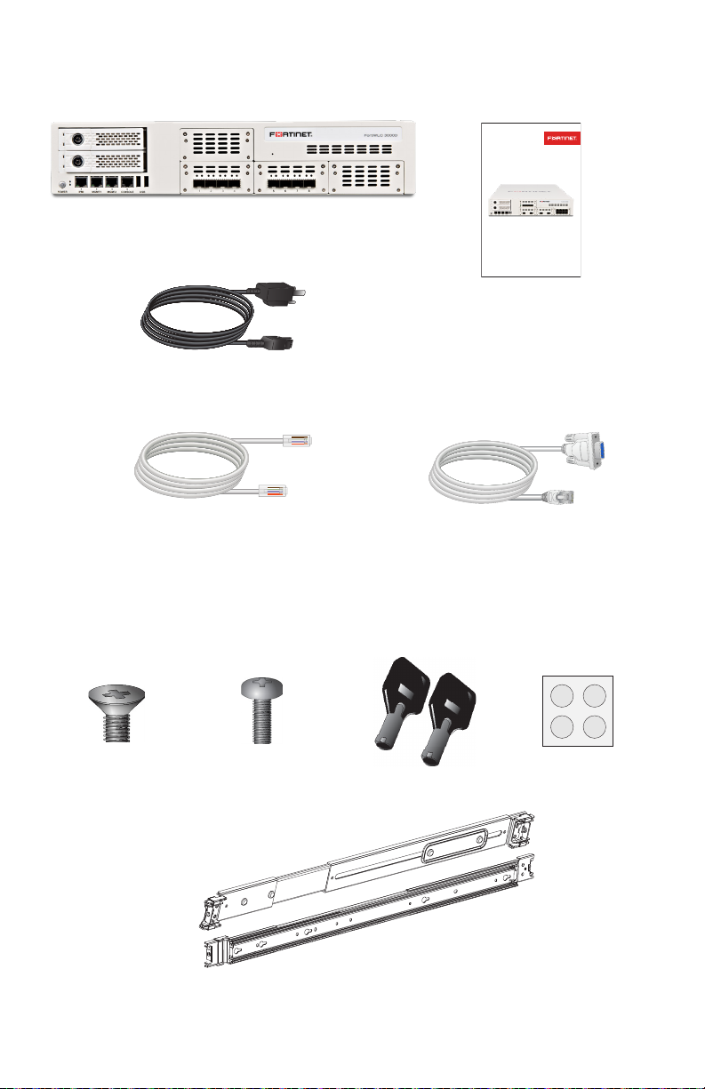
Fortinet FortiWLC 3000D User manual
Other Fortinet Security System manuals

Fortinet
Fortinet FortiGate-5000 Use and care manual

Fortinet
Fortinet FortiAnalyzer-800B User manual

Fortinet
Fortinet FortiGate-5001D User manual

Fortinet
Fortinet FortiDB Series User manual

Fortinet
Fortinet FortiManager-400 User manual

Fortinet
Fortinet FortiCarrier-5001A-DW User manual

Fortinet
Fortinet FortiAnalyzer-800 User manual

Fortinet
Fortinet FortiSwitch-5203B User manual

Fortinet
Fortinet FortiManager-400A User manual

Fortinet
Fortinet FortiGate-5001C User manual

Popular Security System manuals by other brands


Secure
Secure USAB-1 operating instructions

B&B
B&B 480 SERIES Operation & maintenance manual

ADEMCO
ADEMCO VISTA-20P Series Installation and setup guide

Inner Range
Inner Range Concept 2000 user manual

Johnson Controls
Johnson Controls PENN Connected PC10 Install and Commissioning Guide

Aeotec
Aeotec Siren Gen5 quick start guide