FIG. 03
FIG. 02
FIG. 01
FIG. 05 FIG. 06
FIG. 08FIG. 07
FIG. 04
EspañolEnglish
En caso de presiones de funcionamiento superiores a
5 bares (~75 PSI), se aconseja el uso de un reductor
de presión. Antes de efectuar el montaje, se aconseja
purgar las tuberías del agua caliente y fría para
evitar que suciedad y pequeñas impurezas afecten el
funcionamiento del grifo.
INSTALACIÓN EMPOTRAMIENTO PRESSURE BALANCE
FIG. 01
Acabar el revestimiento de la pared y retirar la protección
de plástico (2.A) mediante el uso de un destornillador.
FIG. 02
Apretar en sentido horario las llaves (3.F) con un
destornillador; destornillar la virola (3.B) y extraer el
tapón (3.A). Poner el cartucho (3.C) dentro del cuerpo
empotrado, cerrar con la virola (3.B) de manera que sea
estanco y la manilla tenga movimento suave.
Los grifos pressure balance tienen limitador de
températura para prevenir las quemaduras.
El límite establecido es 100°F max para condiciones
recomendadas (presión y températura agua caliente/
fria).
Si hay necesidad de cambiar el límite, girar la virola
(3.G): a la derecha para una températura inferior, a la
izquierda para una températura superior.
Acabar con la tapa cromada (3.D) y atornillar el
embellecedor (3.E) sobre el grifo empotrado.
Poner el resorte (3.H) sobre el asta del inversor, atornillar
el mando (3.I) sobre el resorte y completar con la tapa
cromada (3.L).
FIG. 03
Montar el florón deslizante (3.D) en la placa (3.F),
para posicionarlo correctamente en el cuerpo del
grifo, interponiendo la junta de esponja (3.G) entre la
placa (3.F) y la pared. Completar la instalación de los
componentes de acabado, posicionando el florón (3.E)
en el cuerpo desviador. Posicionar el cuerpo maneta
(3.A) en el cartucho y fijar con el tornillo prisionero (3.B).
En fin atornillar la palanca (3.C).
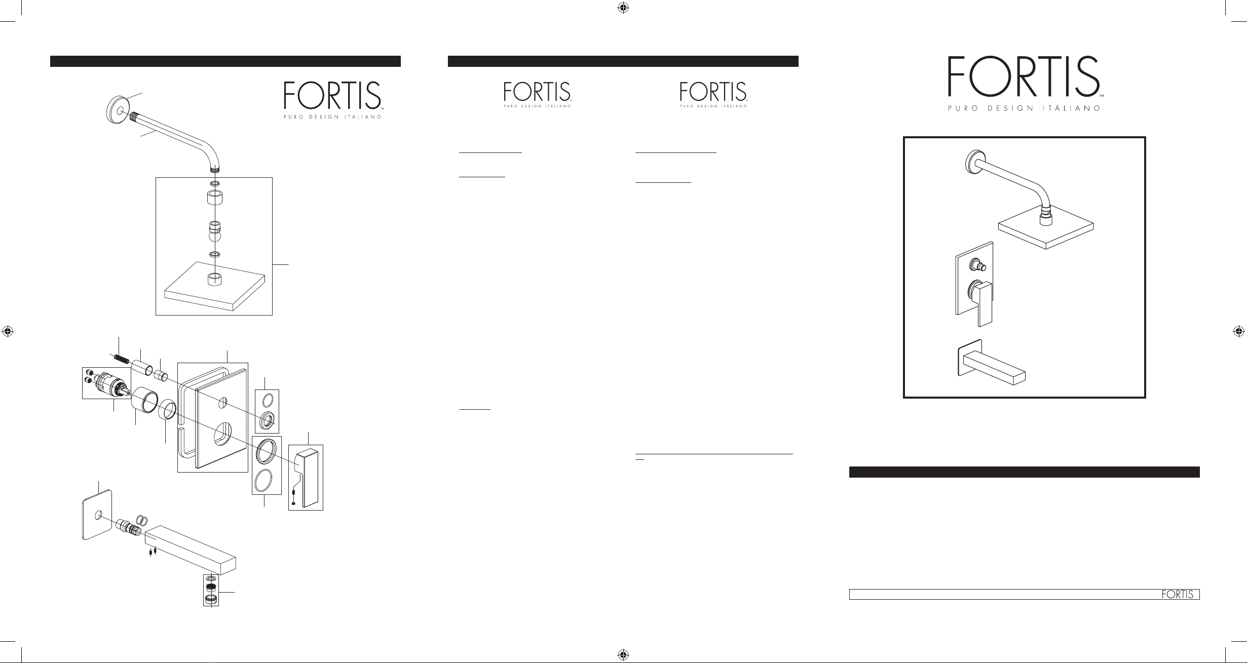
FIG. 04
Montar previamente el florón (4.E) en el brazo de la
ducha (4.D); atornillar este último en el racor de pared.
Apoyar el florón (4.E) a la pared, en fin, montar el
rociador (4.A) en el brazo (4.D) interponiendo la junta
(4.C) y prestando atención a que la válvula antirretroceso
(4.B) esté montada correctamente.
FIG. 05
Atornillar a pared el racor (5.C) interponiendo la placa
(5.D); Aplicar la boca de erogación (5.A) al racor (5.C)
apoyándola a la placa (5.D). Fijar todo atornillando los
tornillos prisioneros roscados (5.B).
In case of pressures over 5 BAR (~75 PSI), we recommend
to use a pressure reducer.
Before proceeding with the assembly, purge the hot and
cold water pipes so as to avoid the accumulation of dirt
and impurities that could affect the function of the faucet.
PRESSURE BALANCE BUILT-IN INSTALLATION
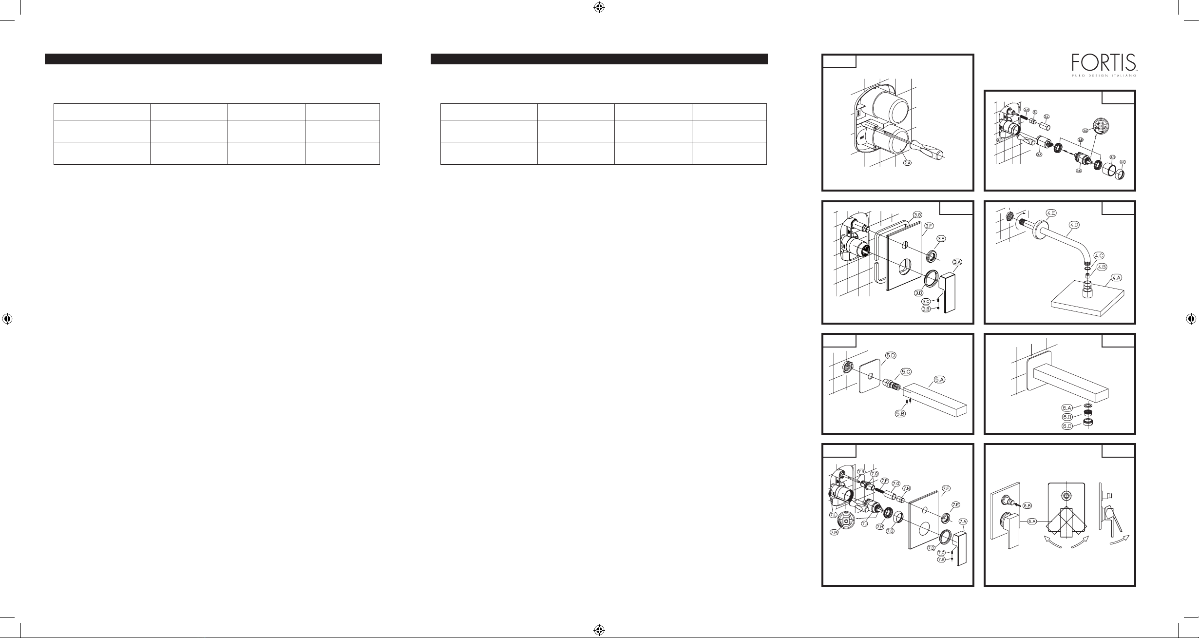
FIG. 01
Finish the wall and remove the plastic cover (2.A) using
a screwdriver.
FIG. 02
Screw the stop valves (3.F) with a screwer, unscrew the
nut (3.B) and remove the cover (3.A). Insert the cartridge
(3.C) into the built-in body, and screw with the nut (3.B)
assuring tight and allowing an easy handling of the lever.
Pressure balance faucets are provided with temperature
restrictor to avoid burns. Restriction is calibrated at 100
°F max for recommended conditions (working pressure
amd hot/cold water temperature).
If necessary to change temperature restriction turn the
ring (3.G) as indicated in the figure: rigth to get a lower
supply temperature, left for a higher supply temperature.
Position the finish cap (3.D) and screw the cover (3.E)
onto the built-in body.
Place the spring on the diverter rod (3.H), screw the knob
(3.I) and the finish cap (3.L).
FIG. 03
Pre-assemble the washer (3.D) on the plate (3.F) correctly
positioning it on the faucet body and place the sponge
(3.G) between the plate (3.F) and the wall.
Complete the installation of the finishing components
fitting the rosette (3.E) on the diverter.
Place the handle (3.A) on the cartridge and tighten the
grub screw (3.B), then screw on the lever (3.C).
FIG. 04
Pre-assemble the rosette (4.E) on the shower arm (4.D);
screw the shower arm on the wall joint. Fit the rosette
(4.E) so that it is flush to the wall and install the shower
head (4.A) on the arm (4.D) positioning the gasket (4.C)
in between. Make sure the check valve (4.B) is correctly
installed.
FIG. 05
Screw the joint (5.C) all the way in fitting the plate (5.D)
in between; install the spout (5.A) on the joint (5.C) till it is
flush to the plate (5.D). Fasten the assembly by tightening
the threaded grub screws (5.B).
FIG. 06
Es oportuno limpiar periódicamente el aireador para
evitar la acumulación de residuos y caliza que con el
tiempo es causa de una gradual disminución del caudal.
Para efectuar el desmontaje del aireador destornillar la
abrazadera (6.C) y eliminar las impurezas del filtro (6.B).
Montar nuevamente procediendo en sentido inverso,
asegurándose de colocar correctamente la junta (6.A).
FIG. 07
En caso de que fuera necesario sustituir el cartucho,
destornillar la palanca (7.C), destornillar el tornillo
prisionero de fijación (7.B) y retirar la maneta (7.A).
Extraer las arandelas (7.D-7.E) que incluyen las juntas
y retirar la placa (7.F). Con un destornillador cerrar las
válvulas de retención (7.L) con una simple rotación de
90°. Destornillar el capuchón (7.G), la abrazadera (7.H)
y retirar el cartucho (7.I).
Para sustituir el desviador, destornillar el capuchón de
acabado (7.O) y destornillar el cuerpo desviador (7.Q)
con una llave adecuada. Destornillar el pomo (7.N) de
la varilla (7.R) y sustituir los componentes necesarios.
Montar nuevamente efectuando las operaciones en
sentido inverso, prestando atención al posicionamiento
del muelle de contraste (7.P) del desviador.
Los grifos pressure balance están dotados de limitador de
temperatura para prevenir las quemaduras.
La limitación configurada es 100 °F máx. para
condiciones de instalación recomendadas (presiones y
temperatura agua caliente/fría). Si es necesario variar
la limitación, girar la específica abrazadera (7.M)
indicada en la figura: en sentido horario para obtener
una temperatura de erogación más baja, en sentido
antihorario para una temperatura más alta.
FIG. 08
Accionando la palanca de mando (8.A), el agua en
salida se dirigirá hacia la boca de erogación.
En caso de que fuera necesario desviar el flujo del agua
hacia la ducha teléfono, es necesario presionar el pomo
desviador (8.B) como se indica en la figura.
MANTENIMIENTO DE LAS SUPERFICIES
Durante la limpieza la superficie del grifo debe estar fría
(el calor acelera el desgaste de la superficie misma).
Asegurarse de que los productos para la limpieza no
contengan ácidos o sustancias corrosivas. El grifo debe
ser secado diariamente con un paño suave. Evitar
absolutamente esponjas de acero, esponjas abrasivas u
otros productos similares. Inmediatamente después de la
limpieza, enjuagar bien los residuos de detergente con
agua fría. Los daños a los grifos debidos a un tratamiento
no adecuado no están cubiertos por la garantía.
FIG. 06
We recommend to periodically clean the aerator so as to
prevent the accumulation in time of debris and limestone
which may gradually reduce the flow. To disassemble the
aerator loosen the lock nut (6.C) and clean the filter (6.B).
Reassemble in reverse order making sure to correctly
position the gasket (6.A).
FIG. 07
To replace the cartridge, pull out the lever (7.C), loosen
the grub screw (7.B) and remove the handle (7.A). Slide
off the flat washers (7.D-7.E) with the gaskets and pull off
the plate (7.F). With a screwdriver rotate the stop valves
(7.L) by 90° to close them.
Screw off the protection cylinder (7.G) and the lock nut
(7.H) and remove the cartridge (7.I).
To replace the diverter, screw off the finishing cover (7.O)
and the diverter body (7.Q) using the proper wrench.
Remove the knob (7.N) from the bar (7.R) and replace the
required elements. Reassemble in reverse order carefully
positioning the return spring (7.P) of the diverter.
Pressure balance faucets are equipped with an anti-
scalding temperature limiting device.
The faucet is pre-set at 100 °F max for recommended
system conditions (hot/cold water pressure and
temperature).
To adjust the temperature, rotate the lock nut (7.M)
shown: clockwise to decrease the water temperature,
counter-clockwise to increase it.
FIG. 08
Move the lever (8.A) to start the water flow. Press the
diverter knob (8.B) as shown to divert the water flow to
the hand shower.
MAINTENANCE OF THE SURFACES
Before cleaning, make sure the faucet is cold (heat wears
the surface of the faucet down). Do not use products
containing acids or corrosive substances. Wipe the
faucet daily with a soft cloth. Do not use steel wool or
metal pads, abrasive sponges or similar products. Right
after cleaning rinse off the detergent residues with cold
water. Damages to the faucets caused by incorrect
treatment are not covered by the warranty.
Water Supply Recommended Maximum Minimum
Hot Water Temperature 65 C° (~150F) 80 C° (~175F) 15 C° (~60F)
Working Pressure 3 BAR (~45PSI) 5 BAR (~75PSI) 0.5 BAR (~7PSI)
Alimentación Recomendada Máxima Mínima
Temperatura agua
caliente
65 C° (~150F) 80 C° (~175F) 15 C° (~60F)
Presión de
funcionamiento
3 BARES (~45PSI) 5 BARES (~75PSI) 0.5 BARES (~7PSI)
INSTALLATION INSTRUCTIONS INSTRUCCIONES DE INSTALACIÓN
Based on its policy of steady development Fortis reserves the right to change the characteristics
of the products without notice and therefore the images and data contained in this catalogue may vary.
Por su política de continuo desarrollo, Fortis se reserva el derecho de modificar las características de los productos sin ningún aviso
previo; por tanto, las imágenes y los datos contenidos en el presente catálogo deben considerarse a título indicativo.
Istruz. art. 8479700.indd 4-6 06/06/11 08:36