Fostex 5042 User manual
Service Manual
Model
16TRACK DIGITAL RECORDER
8TRACK DIGITAL RECORDER
&
MODEL 8345 TC/SYNC CARD
MODEL 5042 / 5043 BALANCE I/O CARD
MODEL 8350 AES/EBU CARD

SAFETY INSTRUCTIONS
Read instructions - All the safety and operating instruc-
tions should be read before the appliance is operated.
Retain instructions - The safety and operating instructions
should be retained for future reference.
Heed warnings - All warnings on the appliance and in the
operating instructions should be adhered to.
Follow instructions - All operating and use instructions
should be followed.
Water and Moisture - The appliance should not be used
near water - for example, near a bathtub, washbowl,
kitchen sink, laundry tub, in a wet basement, or near a
swimming pool, and the like.
Carts and Stands - The appliance should be used only
with a cart or stand that is recommended by the manufac-
turer.
An appliance and cart combination should be moved with
care. Quick stops, excessive force, and uneven surfaces
may cause the appliance and cart combination to over-
turn.
Wall or Ceiling Mounting - The appliance should be
mounted to a wall or ceiling only as recommended by the
manufacturer.
Ventilation - The appliance should be situated so that its
location or position does not interfere with its proper ven-
tilation. For example, the appliance should not be situ-
ated on a bed, sofa, rug, or similar surface that may block
the ventilation openings; or, placed in a built-in installa-
tion, such as a bookcase or cabinet that may impede the
flow of air through the ventilation openings.
Heat - The appliance should be situated away from heat
sources such as radiators, heat registers, stoves, or other
appliances (including amplifiers) that produce heat.
Power Sources - The appliance should be connected to a
power supply only of the type described in the operating
instructions or as marked on the appliance.
Grounding or Polarization - The precautions that should
be taken so that the grounding or polarization means of
an appliance is not defeated.
Power Cord Protection - Power supply cords should be
routed so that they are not likely to be walked on or
pinched by items placed upon or against them, paying
particular attention to cords at plugs, convenience recep-
tacles, and the point where they exit from the appliance.
Cleaning - The appliance should be cleaned only as rec-
ommended by the manufacturer.
Nonuse Periods - The power cord of the appliance should
be unplugged from the outlet when left unused for a long
period of time.
Object and Liquid Entry - Care should be taken so that
objects do not fall and liquids are not spilled into the en-
closure through openings.
Damage requiring Service - The appliance should be ser-
viced by qualified service personnel when:
A.
B.
C.
D.
E.
Servicing - The user should not attempt to service the ap-
pliance beyond that described in the operating instruc-
tions. All other servicing should be referred to qualified
service personnel.
REFER SERVICING TO QUALIFIED SERVICE PERSONNEL.
CAUTION
RISK OF ELECTRIC SHOCK
DO NOT OPEN
CAUTION: TO REDUCE THE RISK OF ELECTRIC SHOCK,
DO NOT REMOVE COVER (OR BACK).
NO USER-SERVICEABLE PARTS INSIDE.
TO PREVENT ELECTRIC SHOCK, MATCH
WIDE BLADE OF PLUG TO WIDE SLOT,
FULLY INSERT.
POUR ÉVITER LES CHOCS ÉLECTRIQUES,
INTRODUIRE LA LAME LA PLUS LARGE DE
LA FICHE DANS LA BORNE CORRE-
SPONDANTE DE LA PRISE ET POUSSER
JUSQU' AU FOND.
CAUTION:
ATTENTION:
The exclamation point within an equilateral
triangle is intended to alert the user to the
presence of important operating and mainte-
nance (servicing) instructions in the literature
accompanying the appliance.
The lightening flash with arrowhead symbol,
within an equilateral triangle, is intended to
alert the user to the presence of uninsulated
“dangerous voltage” within the product's en-
closure that may be of sufficient magnitude to
constitute a risk of electric shock to persons.
“WARNING”
“TO REDUCE THE RISK OF FIRE OR ELECTRIC SHOCK,
DO NOT EXPOSE THIS APPLIANCE TO RAIN OR MOIS-
TURE.”
1.
2.
3.
4.
5.
6.
7.
8.
The power supply cord or the plug has been damaged;
or
Objects have fallen, or liquid has been spilled into the
appliance; or
The appliance has been exposed to rain; or
The appliance does not appear to operate normally or
exhibits a marked changed in performance; or
The appliance has been dropped, or the enclosure
damaged.
9.
10.
11.
12.
13.
14.
15.
16.
17.

3
D1624 / D824
Parts marked with this sign are safety critical components. They must always be replaced with identical
components. Refer to the Fostex Parts List and ensure exact replacement.
CAUTION
TABLE OF CONTENTS
D1624 / D824 English owner's manual : 8288461000
D1624 / D824 Japanese owner's manual : 8288462000
D1624 / D824 English quick guide : 8288463000
D1624 / D824 Japanese quick guide : 8288464000
Service mode, exploded view, PCB assembly, parts list and circuit diagrams are given in this manual
to assist the service technician in maintaining the Model D1624 / D824.
NOTES
The following accessories are supplied with D1624 / D824 as the standard accessories.
*
*
Following is the packing material for the Model D1624 / D824.
*
Carton, inner, D1624 : 8228731000
Carton, outer, D1624 : 8228910000
Carton, inner, D824 : 8228736000
Carton, outer, D824 : 8228914000
Packing, side, L, D1624 / D824 : 8228430001
Packing, side, R, D1624 / D824 : 8228430002
Packing, case, D1624 / D824 : 8228435000
!
1. SPECIFICATIONS . . . . . . . . . . . . . . . . . . . . . . . . . . . . . . . . . . . . . . .
2. CONTROLS, INDICATORS & CONNECTORS . . . . . . . . . . . . . . .
3. SOFTWARE UPDATE . . . . . . . . . . . . . . . . . . . . . . . . . . . . . . . . . .
4. SERVICE MODE . . . . . . . . . . . . . . . . . . . . . . . . . . . . . . . . . . . . .
5. ERROR CODE LIST . . . . . . . . . . . . . . . . . . . . . . . . . . . . . . . . . . . . .
6. MODEL 8345/5042/5043/8350 INSTALLING PROCEDURES . . . . .
7. EXPLODED VIEW, PCB ASSEMBLY & PARTS LIST . . . . . . . . . .
8. CIRCUIT & BLOCK DIAGRAMS . . . . . . . . . . . . . . . . . . . . . .
4
8
11
12
22
23
30
58

4
D1624 / D824
1. SPECIFICATIONS
D824 / D1624
INPUT & OUTPUT
INPUT (1 ~ 8)
Connector RCA pin jack (x 8)
Input Level -10 dBV
Input Impedance 10 kΩor more
OUTPUT (D824: 1 ~ 8, D1624: 1 ~ 16)
Connector RCA pin jack (x 8: D824, x 16: D1624)
Output Level -10 dBV
Load Impedance 10 kΩor more
DATA IN / OUT (D824: 1 ~ 8, D1624: 1 ~ 8 & 9 ~ 16)
Connector Square shape optical
Format IEC consumer optical standard (IEC 60958 Part 3)
Alesis Proprietary Multichannel Optical Digital Interface
(ADAT format does not comply to 96 kHz sampling frequency.)
MIDI IN / OUT /THRU
Connector DIN 5-pin
Format Comply to MIDI standard
WORD IN / OUT
Connector BNC
Level TTL level
REMOTE IN /THRU
Connector D-SUB 9-pin
Transfer Format RS-422
Protocol Sony 9-pin (P2) protocol, ES bus
SCSI
Connector D-SUB 50-pin (half pitch)
Protocol SCSI-2, unbalanced transfer method
Transfer Type Asynchronous
Number of Unit Connected 1
PUNCH IN / OUT
Connector Ø6 mm phone jack
Level CMOS (HIGH: 3.5 ~ 5 V, LOW: 0 ~ 1.5 V)
RECORD & PLAYBACK
Recording Medium Internal 3.5” E-IDE hard disk drive (optional)
Backup Medium External fixed / removable SCSI-2 SCSI device (backup only)
Standard SCSI-2 or better
Sampling Frequency 44.1 kHz, 48 kHz, 96 kHz (Switchable by Disk Format)
Quantization 16-bit linear, 24-bit linear (Switchable by Disk Format)
A-to-D Converter 24-bit delta-sigma 128 times over sampling
D-to-A Converter 24-bit delta-sigma 128 times over sampling
Recording Format FDMS-3Version 2
Emphasis Not available
RecordingTime (mono track min.) About 18 min. / 100 MB at maximum (at 44.1 kHz)
Number ofTracks 24tracks(D824:8+16additionaltracks,D1624:16+8additionaltracks)
Number of RecordingTracks at a Time
D824 8
D1624 16 (when using DATA IN), 8 (Analog only or at 24-bit / 96 kHz)

5
D1624 / D824
Number of playback tracks at a time
D824 8
D1624 16, 8 (at 24-bit / 96 kHz)
No. of Programs 99
Pitch Control ± 6.0 % (0.1 % step)
Crossfade 10 msec (at 44.1 / 48 kHz), 5 msec (at 96 kHz)
Overall Frequency Response 20 ~ 20 kHz ± 1 dB (at 44.1 / 48 kHz)
20 ~ 43 kHz ± 2 dB (at 96 kHz)
Signal to Noise Ratio 100 dB or more (betweenADC and DAC, 24-bit)
Dynamic Range 100 dB or more (betweenADC and DAC, 24-bit)
T.H.D. 0.01 % or less (at 1 kHz, -10 dBV, 24-bit)
Channel Separation 80 dB or more (at 1 kHz, 0 dB, 24-bit)
Phase difference between channels 20 º or less (at 20 kHz)
OPERATION
Shuttle Speed 8 steps (7 steps for FWD direction)
CUE ON ± 1 ~ 8 times (FWD: ± 1 ~ 7 times)
CUE OFF ± 1 ~ 64 times
FFWD / REW Speed
CUE ON ± 3 times
CUE OFF ± 32 times
Digital Scrubbing (JOG) 0~1times(Envelopecanbedisplayedwhenselectingonlyonetrack.)
Locate Memory 6 (7 including [LOCATE] key temporary memory) + 99
Level Indication
Type FL Bargraph
Number of Indicated Levels 11 dots (-∞, -42, -30, -24, -18, -12, -9, -6, -3, 0, OVER)
Reference Level (-10 dBV) Indication - 12 dB
Full Scale Output Level + 2 dBV ± 1 dB
GENERAL
Dimensions 482 (W) x 148 (H) x 381 (D) mm
Weight 7.0 kg
Power Supply
JPN 100VAC
USA / CND 120VAC
EUR / UK 230VAC
Power Consumption
D824 Approx. 30 W
D1624 Approx. 35 W
Standard Environment
StandardTemperature 20 ± 2 ºC
Standard Humidity 65 ± 5 %
ENVIRONMENT CONDITION (W/O HD)
Characteristics Guaranteed
Temperature + 5 ~ + 40 ºC
Humidity 30 ~ 70 %
AC voltage deviation ± 5 % or less
Operation Guaranteed
Temperature 0 ~ + 45 ºC
Humidity 85 % or less
AC voltage deviation ± 10 % or less

6
D1624 / D824
8345
INPUT & OUTPUT
TIME CODE INPUT
Format SMPTE/EBU
Connector XLR-3-31 type (Pin 1: GND, Pin 2: HOT, Pin 3: COLD)
Standard Input Level 2V p-p
Minimum Input Level 0.25V p-p
Input Impedance 20 kΩor more
TIME CODE OUTPUT
Format SMPTE/EBU
Connector XLR-3-32 type (Pin 1: GND, Pin 2: HOT, Pin 3: COLD)
Standard Output Level 2V p-p
Minimum Output Level 0.25V p-p
Load Impedance 20 kΩor more
VIDEO INPUT
Format Composite (Applied video signal must comply to PAL or NTSC
standard and be interlace type.)
Connector BNC
Frame Pulse 24, 25, 29.97, 30 Hz (± 1000 ppm)
Field Pulse 48, 50, 59.94, 60 Hz (± 1000 ppm)
Standard Input Level 1V p-p
Input Impedance 75 Ω(ON / OFF by terminator SW)
VIDEOTHRU
Connector BNC
Output Level Direct output of signal fed toVideo Input connector
WORD INPUT
Connector BNC
Frequency 44.1 kHz, 48 kHz
Standard Input Level TTL level
Input Impedance 75 Ω(ON / OFF by terminator SW)
WORD OUTPUT
Connector BNC
Standard Output Level TTL level
Load Impedance 75 Ω
GENERAL
Dimensions 215 (W) x 80 (D) mm
Power Supply Supplied from main unit
Digital DC + 5V
Analog DC + 19V / - 15 V

7
D1624 / D824
5042 / 5043
INPUT & OUTPUT
INPUT (1 ~ 8)
Connector D-SUB 25-pin
Standard Input Level + 4 dBu
Input Impedance 10 kΩor more
OUTPUT (1 ~ 8)
Connector D-SUB 25-pin
Output Level + 4 dBu
Load Impedance 600 Ωor more
OUTPUT (9 ~ 16, Model 5043 only)
Connector D-SUB 25-pin
Output Level + 4 dBu
Load Impedance 600 Ωor more
GENERAL
DIMENSIONS 270 (W) x 70 (D) mm
POWER SUPPLY DC + 15V (Supplied from main unit)
8350Connector D-SUB 25-pin
Format IEC958 PART 3 (AES/EBU)
Pin assignment Indicated below
Recommended cable AES/EBU digital audio transfer cable from Hosa Technology Inc.
DBK-258 (DB-25 (male) ↔4 x XLR (male) & 4 x XLR (female))
13 1
1425
[D-SUB 25-pin Assignment ]
(Seen from rear panel side)SIGNAL
Input 1/2
Input 3/4
Input 5/6
Input 7/8
Output 1/2
Output 3/4
Output 5/6
Output 7/8
HOT
1
2
3
4
5
6
7
8
COLD
14
15
16
17
18
19
20
21
Frame GND 10, 12, 13, 22,
23, 24, 25
Open 9, 11

8
D1624 / D824
2. CONTROLS, INDICATORS & CONNECTORS
Front Panel Section:Main Unit (D1624 / D824)
1. Detachable Controller connector
2. Controller mounter
3. Removable hard disk cartridge slot
4. Lock/Unlock key
5. Hard disk power LED
6. Access LED
7. Power switch
1. Controller Connection Cable
2. Record Track Select / Envelope key
3. Track Shift / All Input key
4. Auto Play/Auto Return key
5. Clipboard In / Preview key
6. Clipboard Out / Preview key
7. Auto Return Start / Preview key
8. Auto Punch In / Preview key
9. Auto Punch Out / Preview key
10. Auto Return End / Preview key
11. Display Select key
12. Program select key
13. Store key
14. Exit/No / Eject key
15. Execute/Yes / Chase key
16. Recall key
17. NEXT key
18. Previous key
19. Jog/Shuttle dial
20. Vari-pitch / Pitch Edit key
21. Fast Forward key
22. Locate key
23. Rewind key
24. Undo/Redo / Multi Undo key
25. Play key
26. Setup / TC Generator Setup key
27. Stop key
28. Edit / TC Ready key
29. Record /All Ready key
30. Auto Punch Mode On/Off key
31. Shift key
32. TC ready LED
33. Access LED
34. All Input LED
35. Punch In/Out jack
36. Meter display
Front Panel Section: Controller (D1624 / D824)
12 3 42
567
12
3
45 678910
11
12
13 14 1516
1718
19
212325272931 202224
26
2830323334
35
36

9
D1624 / D824
Rear Panel Section (D824)
Rear Panel Section (D1624)
1. PanelA for an optional card
2. Panel B for an optional card
3. WORD IN terminating switch
4. WORD INPUT connector [BNC]
5. WORD OUTPUT connector [BNC]
6. MIDI Input/Output/Thru connector
7. AC IN connector
8. REMOTE THRU connector
9. REMOTE INPUT terminating switch
10. REMOTE INPUT connector
11. SCSI connector [half-pitch 50-pin]
12. Digital/Data Output connector [OPTICAL]
13. Digital/Data Input connector [OPTICAL]
14. Analog Output jack [RCA pin]
15. Analog Input jack [RCA pin]
100
ON OFF
CAUTION
RISK OF ELECTRIC SHOCK
DO NOT OPEN
AVIS:
RISQUE DE CHOC ELECTRIQUE NE PAS OUVRIR
WARNING:
TO REDUCE THE RISK OF FIRE OR ELECTRIC
SHOCK, DO NOT EXPOSE THIS EQUIPMENT
TO RAIN OR MOISTURE.
REMOTE
THRU
MIDI
INPUT OUTPUT THRU
INPUT
OFFON
WORD
OUTPUTINPUT
SCSI
8 - 116 - 9 8 - 1 16 - 9
OUTPUTINPUT
DIGITAL/DATA AC INANALOG OUTPUT
ANALOG INPUT
5
1
678
234
13
5
141516
678
9
1
101112
234
OPTICAL
75Ω
12 234 5 6
789101112
131415
REMOTE
THRU
MIDI
INPUT OUTPUT THRU
AC IN
INPUT OUTPUT
WORD
ON OFF
43
ANALOG INPUT
2
87 6
1
5
43
ANALOG OUTPUT
2
87 6
1
5
OUTPUTINPUT
SCSIDIGITAL/DATA
100
ON OFF
OPTICAL
CAUTION
RISK OF ELECTRIC SHOCK
DO NOT OPEN
AVIS:
RISQUE DE CHOC ELECTRIQUE NE PAS OUVRIR
WARNING:
TO REDUCE THE RISK OF FIRE OR ELECTRIC
SHOCK, DO NOT EXPOSE THIS EQUIPMENT
TO RAIN OR MOISTURE.
75Ω
12 234 5 6
789101112
131415

10
D1624 / D824
Rear Panel Section (D824 with Model 5042, 8345 and 8350)
Rear Panel Section (D1624 with Model 5043 and 8345)
[ MODEL 5043 ]
1. Balanced input connector
2. Balanced output connector (9 - 16)
3. Balanced output connector (1 - 8)
[ MODEL 8345]
4. Video input terminating switch
5. Video input connector
6. Video thru connector
7. Word input terminating switch
8. Word input connector
9. Word output connector
10. Time code input connector
11. Time code output connector
[ MODEL 5042 ]
1. Balanced input connector
2. Balanced output connector
[ MODEL 8350 ]
3. Digital input & output connector
[ MODEL 8345 ]
4. Video input terminating switch
5. Video input connector
6. Video thru connector
7. Word input terminating switch
8. Word input connector
9. Word output connector
10. Time code input connector
11. Time code output connector
REMOTE
THRU
MIDI
INPUT OUTPUT THRU
AC IN
INPUT OUTPUT
WORD
75Ω
ON OFF
43
ANALOG INPUT
2
87 6
1
5
43
ANALOG OUTPUT
2
87 6
1
5
OUTPUTINPUT
SCSIDIGITAL/DATA
100
ON OFF
OPTICAL
CAUTION
RISK OF ELECTRIC SHOCK
DO NOT OPEN
AVIS:
RISQUE DE CHOC ELECTRIQUE NE PAS OUVRIR
WARNING:
TO REDUCE THE RISK OF FIRE OR ELECTRIC
SHOCK, DO NOT EXPOSE THIS EQUIPMENT
TO RAIN OR MOISTURE.
INPUT
OUTPUT
INPUT THRU
VIDEO
75Ω
ON OFF
+4dBu INPUT
ANALOG BALANCE I/O
+4dBu OUTPUT
TIME CODE
3
2
1
COLD
GND
HOT
8-1 I/O
AES/EBU
123
45 9
810
76 11
100
ON OFF
CAUTION
RISK OF ELECTRIC SHOCK
DO NOT OPEN
AVIS:
RISQUE DE CHOC ELECTRIQUE NE PAS OUVRIR
WARNING:
TO REDUCE THE RISK OF FIRE OR ELECTRIC
SHOCK, DO NOT EXPOSE THIS EQUIPMENT
TO RAIN OR MOISTURE.
REMOTE
THRU
MIDI
INPUT OUTPUT THRU
INPUT
OFFON
75Ω
WORD
OUTPUTINPUT
SCSI
8 - 116 - 9 8 - 1 16 - 9
OUTPUTINPUT
DIGITAL/DATA AC INANALOG OUTPUT
ANALOG INPUT
5
1
678
234
13
5
141516
678
9
1
101112
234
OPTICAL
HOT
GND
COLD
1
2
3
TIME CODE
OFFON
75Ω
VIDEO
THRUINPUT OUTPUT
INPUT
+4dBu OUTPUT 8-1+4dBu OUTPUT 16-9
ANALOG BALANCE I/O
+4dBu INPUT 8-1
123
45 9
810
76 11

11
D1624 / D824
3. SOFTWARE UPDATE
Since the 8Mbit flash ROM is mounted on the MAIN PCB assy, the D1624/D824 software can be updated through the
SCSI port. Please refer to the following explanation for correct software updating procedures.
3-1. Required Tools
The following tools/equipment are required to update the D1624/D824 software.
1. IBM PC/AT compatible computer with SCSI board
2. Removable type SCSI drive
3. Cable between the removable type SCSI drive and the SCSI board
4. Cable between the removable type SCSI drive and the D1624/D824 (D-SUB half-pitch 50-pin)
5. A Utility software to extract the WinZip compressed file
3-2. Software Updating Procedures
Presuming that the updated software is correctly sent to you via email and is copied into your computer.
1. Connect the removable type SCSI drive to the IBM PC/AT compatible computer SCSI port.
2. Insert the diskette to the removable type SCSI drive and format it by the computer on which Windows 95/98 is
running.
3. Using the utility software, extract the WinZip compressed software file. The extracted file name is “d1624mvX.XX”.
(X.XX indicates the version number. For example, if the software version number is V1.06, the file name is
d1624mv1.06.)
3. Copy the updated software file “d1624mvX.XX” to the removable type SCSI drive (diskette).
4. Set the removable type SCSI drive ID to 6 and connect to the D1624/D824 SCSI port (D-SUB half-pitch 50-pin).
5. Turn on the power of removable drive and then D1624/D824.
6. Insert the diskette with updated software file.
7. The D1624/D824 automatically finds the software update file in the SCSI drive/disk and is put into the software
update mode. In this condition, “SystemUp” is displayed and “SURE?” is blinking on the FL display.
44.1kHz
SURE?
42
_
OL
0
30
24
18
12
9
6
3
12345678910111213141516
8. Press the [EXECUTE/YES] key to start updating the software.
9. The D1624/D824 FL display shows “Loading !”, “Writing !”, etc and after a while, “SystemUp” appears on the
FL display again. This indicates that the software is correctly updated. Press the [STOP] key or [EXIT/NO] key to
eject the disk.
10. Turn off the D1624/D824 and the connected SCSI drive.
11. Disconnect the SCSI drive from the D1624/D824 and power on the D1624/D824 again.
12. Confirm the software version number and the programming date while in the boot up procedures. For your
information, they can also be checked by the Service Mode explained later.
44.1kHz
42
∞
_
OL
0
30
24
18
12
9
6
3
12345678910 11 12 13 14 15 16
SETUP
: Blinking
[CAUTION]
In case the D1624/D824 does not find the software update file in the external SCSI drive by itself, please follow the
procedures below.
1..6. Same as the before mentioned procedures.
7. Press the [SETUP] key.
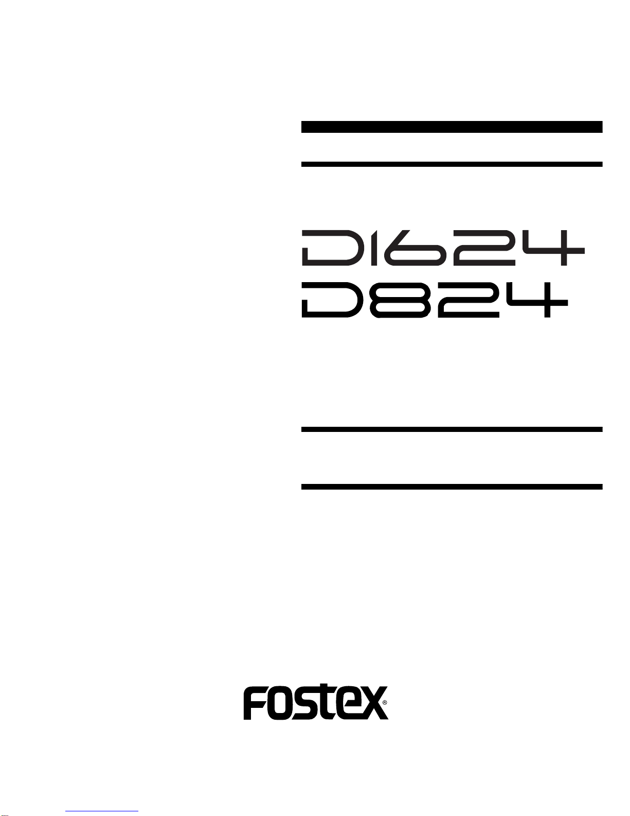
8. Rotate the jog wheel, select the “Drive Sel?” menu and press the [EXECUTE/YES] key.
12
D1624 / D824
44.1kHz
42
∞
_
OL
0
30
24
18
12
9
6
3
12345678910111213141516
SETUP
: Blinking
4. SERVICE MODE
There are various optional modes available in the D1624/D824 Service Mode. Please utilize them when servicing the unit.
4-1. Putting D1624/D824 into Service Mode
The way of putting the D1624/D824 into Service Mode is as follow.
1. Plug a 3.5” E-IDE HDD caddy into the D1624/D824 HD bay and lock it using the HD key.
2. Power on the D1624/D824.
3. While holding down the [STOP] key and [TRACK SHIFT/ALL INPUT] key, press the [SETUP] key.
As shown below, by rotating the jog dial C.W. or C.C.W., various optional modes will be displayed in addition to the
general SETUP menus. In order to select a certain optional mode, press the [EXECUTE/YES] key while the menu is
displayed.
44.1kHz
42
∞
_
OL
0
30
24
18
12
9
6
3
12345678910 11 12 13 14 15 16
SETUP
: Blinking
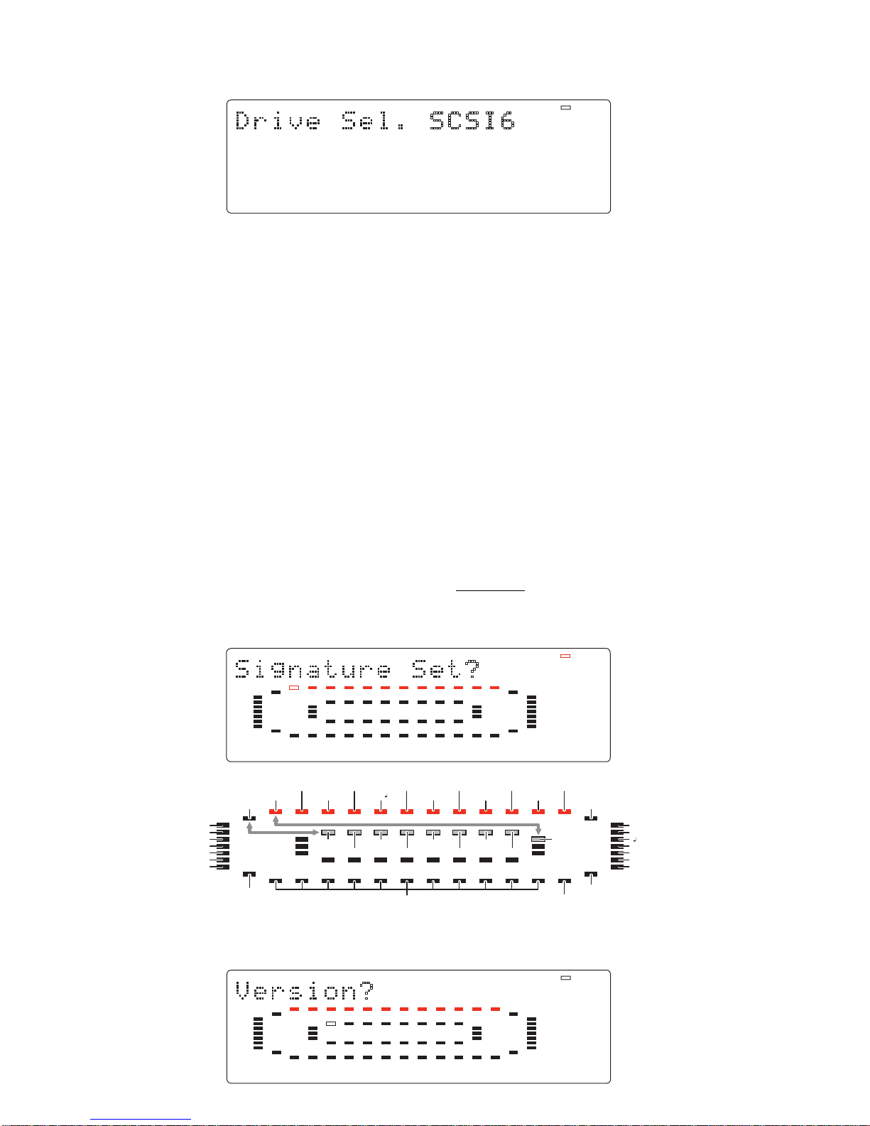
Tempo Map Set? Delete PGM? Preroll Time? Frame Rate? Offset Mode? Slave Type?
Signature Set? Title Edit? Click ? Midi Sync Out?
Version?DA Test?
Standby Disk?
Display Test?
Self Check?
Offset Disp?
Initial Disk?
Flash ROM?
MTC offset? Ref. TC?
Drive Info? Offset Disp?
Virtual LTC?
Reserved
Rec Protect?Disk Format?
Digital In?
Digital Out?
Resolution?
Device ID?
Clock Sel?
Sync Preset?
NOs Of Event?
Reserved
Disk Optimize?
Reserved
Date & Time set?
Save PGM?
Load pGM?
Drive Sel?
Freeblock Check?
9. Select “SCSI-6” and press the [EXECUTE/YES] key.
10. The D1624/D824 recognizes the software file in the connected SCSI drive/diskette and is automatically put into
the software update mode.
11. Press the [EXECUTE/YES] key to start updating the software.
12. The D1624/D824 FL display shows “Initial...”, name of the drive, “Loading...” and “Writing...” in order and after
a while, “SURE?” will start blinking again. This indicates that the software is correctly updated. Press the [STOP]
key or [EXIT/NO] key to eject the disk.
13. Turn off the D1624/D824 and the connected SCSI drive.
14. Disconnect the SCSI drive from the D1624/D824 and power on the D1624/D824 again.
15. Confirm the software version number and the programming date while in the boot up procedures. They can also
be checked by the Service Mode explained later.
4-2. Flash ROM (software) version
This mode is used to check the Flash ROM (software) versions currently installed in the unit.
44.1kHz
42
∞
_
OL
0
30
24
18
12
9
6
3
1234567891011 12 13 14 15 16
: Blinking

13
D1624 / D824
44.1kHz
42
_
OL
0
30
24
18
12
9
6
3
12345678910111213141516
4-3. DA Test
This mode tests the signal flow from the DATA INPUT jack to the D/A converter. A S/P DIF digital signal (Fs:
44.1kHz) must be input to the DATA INPUT jack to execute this test. Then, press the [EXECUTE/YES] key while “?”
44.1kHz
42
∞
_
OL
0
30
24
18
12
9
6
3
12345678910 11 12 13 14 15 16
: Blinking
44.1kHz
EXT SYNC
DIGITAL
42
∞
_
OL
0
30
24
18
12
9
6
3
1234567891011 12 13 14 15 16
is blinking. If the D1624/D824 is in a normal condition, “44.1kHz” and “DIGITAL” will be lit solid. The odd (1, 3, 5,
7, 9, 11, 13, 15) and even (2, 4, 6, 8, 10, 12, 14, 16) channels indicate the left and right input level of S/P DIF digital
signal fed to the DATA INPUT jack respectively.
If the D1624/D824 is not in a normal condition, “DIGITAL” and “EXT SYNC” on the display will blink and the
bargraph meter will not indicate any level.
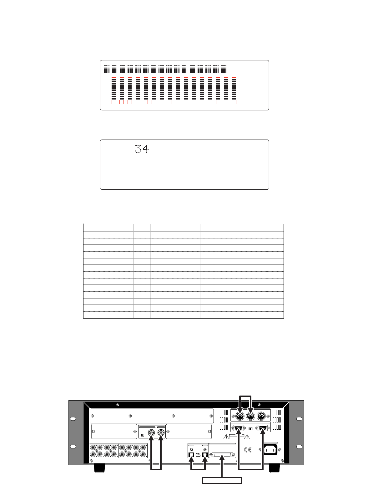
In order to check the version number, press the [EXECUTE/YES] key while “?” is blinking.
The example on the above indicates that the Flash ROM version is V1.05 and its programming date is April 3, 2000.
4-4. Standby Disk
This mode stops spinning the internal hard disk for purposes such as “shock” test. If the [EXECUTE/YES] key is
pressed when “?” is blinking, “SURE?” will start blinking. If you would like to go on, press the [EXECUTE/YES] key
once again. The internal hard disk will stop spinning.
44.1kHz
42
∞
_
OL
0
30
24
18
12
9
6
3
12345678910 11 12 13 14 15 16
: Blinking
4-4. Display/Key Test
This mode tests if all the segments on the FL display, LEDs and keys (switches) on the D1624/D824 controller are
correctly working or not. To execute this test, press the [EXECUTE/YES] key while “?” is blinking.
44.1kHz
42
∞
_
OL
0
30
24
18
12
9
6
3
12345678910 11 12 13 14 15 16
: Blinking
14
D1624 / D824
44.1kHz
SETUP
MTC IN OFFSET
CHASE
LOCATE
PGM
REMAIN FORMAT
SIGNATURE
TEMPO
48kHz
-0.1%
COMPLETED!
SURE?
MIDI CHASE
SAVE LOAD
EXT SYNC
DIGITAL
MTC INTC
ABS
42
∞
_
OL
0
30
24
18
12
9
6
3
1234567891011 12 13 14 15 16
42
∞
_
OL
0
30
24
18
12
9
6
3
12345678910111213141516
If the D1624/D824 is in a normal condition, all the segments on the FL display will be lit solid, dot matrix and bargraph
meter sections on the FL display and all the LEDs on the top panel will start blinking. If the D1624/D824 is not in a
normal condition, faulty segments on the LCD display, dot matrix and/or LEDs on the top panel will remain unlit.
In this condition, if the [EXECUTE/YES] key is pressed one more time, the Key Test can be executed. The Key Test
checks if each key and jog dial are working properly or not. The display below indicates that the [PLAY] key is pressed
and held down.
4-5. Self Check
This mode automatically tests the following points in order.
1. SCSI port →2. ATA (E-IDE) bus →3. Option (Model 8345) bus →4. MIDI in/out circuit
→5. S/P DIF digital signal in/out →6. ADAT digital signal in/out →7. 8345 vari-pitch circuit
→8. Vari-pitch circuit →9. External Time Clock Check →10. Internal Time Clock Check →
11. Remote in/out circuit →12. Word In/Out circuit →13. A/D and D/A circuit (Input Monitor)
REMOTE THRU
MIDI
INPUT OUTPUT THRU
AC IN
INPUT OUTPUT
WORD
75Ω
ON OFF
43
ANALOG INPUT 2
87 6
1
5
43
ANALOG OUTPUT 2
87 6
1
5
OUTPUTINPUT SCSIDIGITAL/DATA
100Ω
ON OFF
OPTICAL
CAUTION
RISK OF ELECTRIC SHOCK
DO NOT OPEN
AVIS:
RISQUE DE CHOC ELECTRIQUE NE PAS OUVRIR
WARNING:
TO REDUCE THE RISK OF FIRE OR ELECTRIC
SHOCK, DO NOT EXPOSE THIS EQUIPMENT
TO RAIN OR MOISTURE.
DIGITALWORD
MIDI
REMOTE
External SCSI Device
Cable connection in “Self Check” mode : D824
Key/Button No. Key/Button No. Key/Button No.
AUTO RTN/PLAY 01 ERASE 14 RECORD TRACK 5 27
CLIPBOARD IN 02 UNDO 15 RECORD TRACK 6 28
CLIPBOARD OUT 03 REDO 16 RECORD TRACK 7 29
AUTO RTN START 04 HOLD/ 17 RECORD TRACK 8 30
AUTO PUNCH IN 05 STORE 18 SHIFT 31
AUTO PUNCH OUT 06 RECALL 19 RECORD 32
AUTO RTN END 07 AUTO PUNCH 20 STOP 33
DISP SEL 08 LOCATE 21 PLAY 34
EXECUTE/YES 09 VARI PITCH 22 REWIND 35
EXIT/NO 10 RECORD TRACK 1 23 F. FWD 36
COPY 11 RECORD TRACK 2 24 SHUTTLE 00~07
MOVE 12 RECORD TRACK 3 25 JOG (C.W.) 51
PASTE 13 RECORD TRACK 4 26 JOG (C.C.W.) 49
The table below shows the relationship between the key/button/jog dial and the corresponding numbers appear on the
FL display.
In order to quit the Button Test, turn the jog dial C.W. or C.C.W. further after “51” or “49” is displayed respectively.
15
D1624 / D824
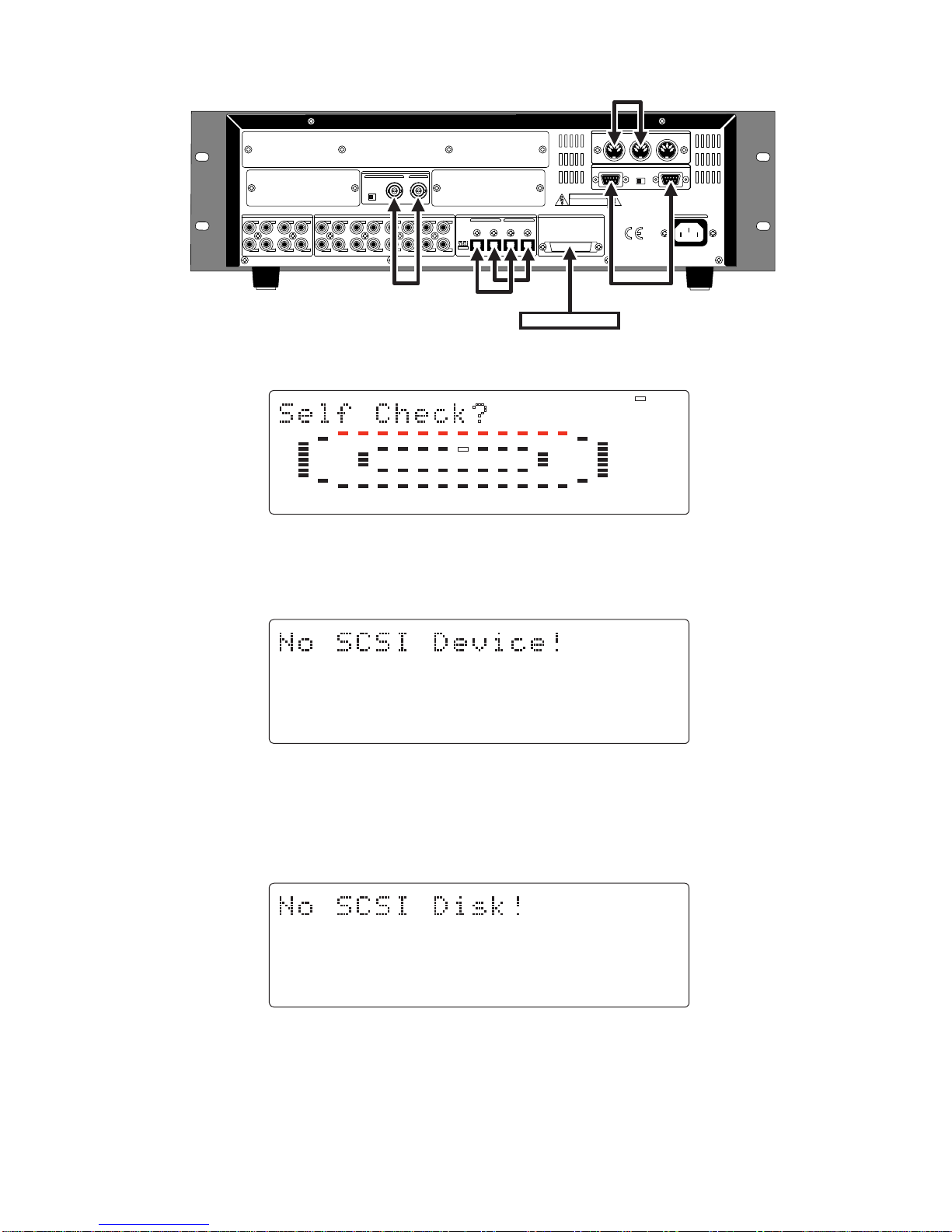
CAUTION: In order not to form a MIDI signal loop, connect the MIDI cable after putting the D1624/D824 into the
Service Mode.
100Ω
ON OFF
CAUTION
RISK OF ELECTRIC SHOCK
DO NOT OPEN
AVIS:
RISQUE DE CHOC ELECTRIQUE NE PAS OUVRIR
WARNING:
TO REDUCE THE RISK OF FIRE OR ELECTRIC
SHOCK, DO NOT EXPOSE THIS EQUIPMENT
TO RAIN OR MOISTURE.
REMOTE
THRU
MIDI
INPUT OUTPUT THRU
INPUT
OFFON
75Ω
WORD
OUTPUTINPUT
SCSI
8 - 116 - 9 8 - 1 16 - 9
OUTPUTINPUT
DIGITAL/DATA AC INANALOG OUTPUT
ANALOG INPUT
5
1
678
234
13
5
141516
678
9
1
101112
234
OPTICAL
DIGITAL
WORD
MIDI
REMOTE
External SCSI Device
Cable connection in “Self Check” mode : D1624
44.1kHz
42
∞
_
OL
0
30
24
18
12
9
6
3
12345678910 11 12 13 14 15 16
: Blinking
4-5-1. SCSI Port Check
If the D1624/D824 does not recognize a connected SCSI device, the prompt below will be displayed.
44.1kHz
42
∞
_
OL
0
30
24
18
12
9
6
3
12345678910111213141516
44.1kHz
42
∞
_
OL
0
30
24
18
12
9
6
3
12345678910111213141516
The following is considered to be the cause of problem.
• Bad cable connection, bad cable contact and / or the power of SCSI device is being turned off.
• SCSI device ID is not set to 6.
• U9, U64, J16, etc and / or surrounding circuit are defective.
• If a removable type SCSI drive is connected and in case a disk is not inserted into the drive, the following prompt
will be displayed.
Fs, DIGITAL IN, DIGITAL OUT and SLAVE MODE settings on the internal hard disk to be used when the Self Check
test is executed should be as follow.
* Fs: 44.1kHz
* DIGITAL IN: OFF (L: -, R: -)
* DIGITAL OUT: ADAT
* SLAVE MODE: OFF
Even if the before mentioned prompt is displayed, pressing the [EXECUTE/YES] key would reach the next test.

16
D1624 / D824
44.1kHz
42
∞
_
OL
0
30
24
18
12
9
6
3
12345678910111213141516
44.1kHz
42
∞
_
OL
0
30
24
18
12
9
6
3
12345678910111213141516
44.1kHz
42
∞
_
OL
0
30
24
18
12
9
6
3
12345678910111213141516
4-5-2. ATA (E-IDE) Bus Check
This test checks if data can be properly read out from the preformatted internal hard disk.
If the “ALTERNATE STATUS” which indicates the hard disk condition cannot be read out, the prompt below will be
displayed.
If the data (SYSTEM ID) written by formatting the disk cannot read out correctly, the prompt below will be displayed.
The following is considered to be the cause of problem.
• Breaking, shortage and / or bad contact of flat cable W12.
• U1, U9, etc and / or surrounding circuit are defective.
Fs, DIGITAL IN, DIGITAL OUT and SLAVE MODE settings on the internal hard disk to be used when the Self Check
test is executed should be as follow.
* Fs: 44.1kHz
* DIGITAL IN: OFF (L: -, R: -)
* DIGITAL OUT: ADAT
* SLAVE MODE: OFF
Even if the before mentioned prompt is displayed, pressing the [EXECUTE/YES] key would reach the next test. If the
[EXECUTE/YES] key is pressed with the “ATA Bus Check” message displayed, checking the SYSTEM ID on the
SCSI device will be executed. The current drive setting after the Self Check test will become “SCSI”.
4-5-3. Option (Model 8345) Bus Check
This test checks if the option bus (J18 on the MAIN PCB) to which the Model 8345 is connected is working properly
or not. If reading out and / or writing in data are not correctly executed, the prompt below will be displayed.
The following is considered to be the cause of problem.
• Bad connection and / or wrongly connected J18.
• J18, U67, U75, etc and / or surrounding circuit are defective.
Even if the before mentioned prompt is displayed, pressing the [EXECUTE/YES] key would reach the next test.

17
D1624 / D824
44.1kHz
42
∞
_
OL
0
30
24
18
12
9
6
3
12345678910111213141516
44.1kHz
42
∞
_
OL
0
30
24
18
12
9
6
3
12345678910111213141516
44.1kHz
42
∞
_
OL
0
30
24
18
12
9
6
3
12345678910111213141516
4-5-4. MIDI In/Out Check
By connecting the MIDI IN and OUT ports, this test checks if the replyagainst the ID inquiry is correctly received. If
not, the prompt below will be displayed.
The following is considered to be the cause of problem.
• J7, U28, U29 (MAIN PCB), J201, J202 (MIDI PCB), J301, J304 (RS422 PCB), etc and / or surrounding circuit are
defective.
Even if the before mentioned prompt is displayed, pressing the [EXECUTE/YES] key would reach the next test.
4-5-5. S/P DIF In/Out Check
By connecting the DATA IN and OUT terminals, this test checks if the S/P DIF signal output by itself is correctly
received. If the PLL circuit is not in a “LOCKED” condition, the prompt below will be displayed.
The following is considered to be the cause of problem.
• No oscillation of resonator X1.
• J11, J12, J20, J21, U4, U5, U17, U19, U24, U62, etc and / or surrounding circuit are defective.
Even if the before mentioned prompt is displayed, pressing the [EXECUTE/YES] key would reach the next test.
4-5-6. Adat In/Out Check
By connecting the DATA IN and OUT terminals, this test checks if theADAT digital signal output by itself is correctly
received. If the PLL circuit is not in a “LOCKED” condition, the prompt below will be displayed.
The following is considered to be the cause of problem.
• No oscillation of resonator X2.
• J11, J12, J20, J21, U4, U5, U17, U19, U24, U62, etc and / or surrounding circuit are defective.
Even if the before mentioned prompt is displayed, pressing the [EXECUTE/YES] key would reach the next test.
18
D1624 / D824
44.1kHz
42
∞
_
OL
0
30
24
18
12
9
6
3
12345678910111213141516
44.1kHz
42
∞
_
OL
0
30
24
18
12
9
6
3
12345678910111213141516
4-5-7. 8345 Vari-Pitch Circuit Check
The master clock is generated using the Model 8345 LRCK (J1 pin-24: EXT_LRCK). In the meantime, the adat digital
signal is generated based on this master clock. This test checks if the adat digital signal output by itself is correctly
received. If not, it means that the vari-pitch circuit does not work correctly. As a result, the prompt below will be
displayed.
If “adat error” is displayed in the before mentionedAdat In/Out Check test, the above error prompt will be displayed.
If the Model 8345 is not installed in the D1624/D824, this test will be skipped.
The following is considered to be the cause of problem.
• Wrongly connected flat cable to J18 on the MAIN PCB.
• J18, U67, U75, etc and / or surrounding circuit are defective.
Even if the before mentioned prompt is displayed, pressing the [EXECUTE/YES] key would reach the next test.
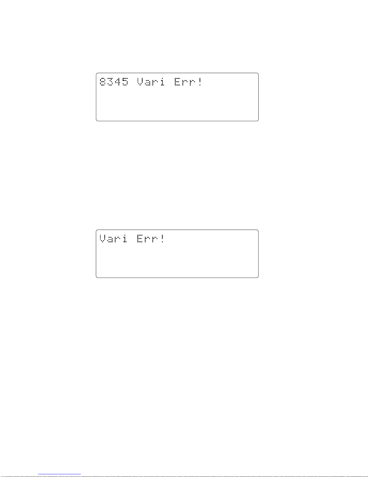
4-5-8. D1624/D824 Vari-Pitch Circuit Check
Using the master clock generated through the D1624/D824 vari-pitch circuit on the MAIN PCB, the adat digital signal
is output. This test checks if the adat digital signal output by itself is correctly received. If not, it means that the vari-
pitch circuit does not work correctly. As a result, the prompt below will be displayed.
If “adat error” is displayed in the before mentionedAdat In/Out Check test, the above error prompt will be displayed.
If the Model 8345 is not installed in the D1624/D824, this test will be skipped.
The following is considered to be the cause of problem.
• U1, U2, U17, etc and / or surrounding circuit are defective.
Even if the before mentioned prompt is displayed, pressing the [EXECUTE/YES] key would reach the next test.
4-5-9. External Time Clock Check
This mode checks the internal RTC (Real Time Clock) controlling circuit when the power is at OFF condition.
The following is considered to be the cause of problem.
• Defects on the U86.
Even if the before mentioned prompt is displayed, pressing the [EXECUTE/YES] key would reach the next test.
4-5-10. Internal Time Clock Check
This mode checks the internal RTC (Real Time Clock) controlling circuit when the power is at ON condition.
The following is considered to be the cause of problem.
• Defects on the U1.
Even if the before mentioned prompt is displayed, pressing the [EXECUTE/YES] key would reach the next test.
19
D1624 / D824
44.1kHz
42
∞
_
OL
0
30
24
18
12
9
6
3
12345678910111213141516
44.1kHz
42
∞
_
OL
0
30
24
18
12
9
6
3
12345678910111213141516
44.1kHz
42
∞
_
OL
0
30
24
18
12
9
6
3
12345678910 11 12 13 14 15 16
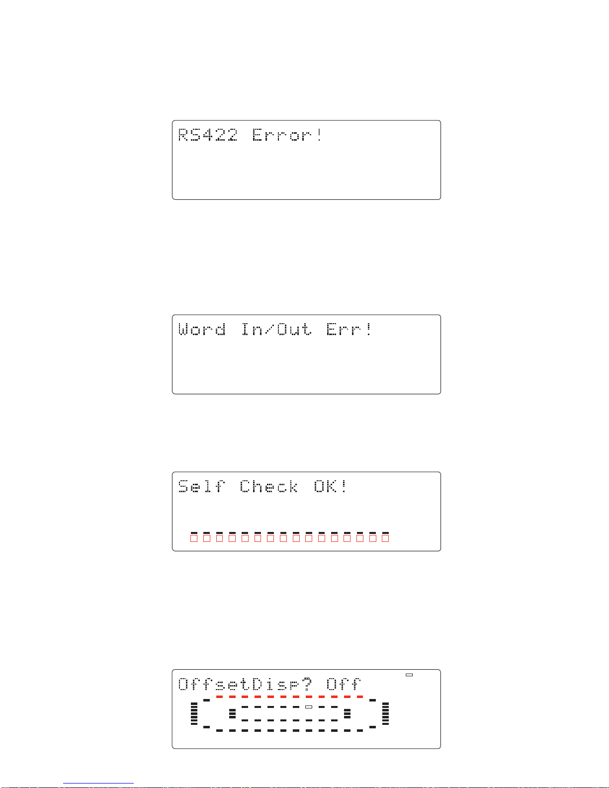
4-5-13. A/D and D/A Circuit Check (Input Monitoring)
The D1624/D824 automatically checks the before mentioned points in the Self Check mode. If the D1624/D824 is
working properly, the following appears on the display with REC LED blinking.
In order to go back to the normal display, press the [EXIT/NO] key or STOP button.
4-6. Offset Display
This mode determines if the offset value against a master machine should be displayed when the D1624/D824 is
working as a slave machine. If you would like to turn ON the offset display, press the [EXECUTE/YES] key while “?”
is blinking. (The default setting is “off”.) Then, turn the jog dial C.W. to change the display to “ON” and press the
[EXECUTE/YES] key.
44.1kHz
SETUP
42
∞
_
OL
0
30
24
18
12
9
6
3
12345678910 11 12 13 14 15 16
: Blinking
4-5-11. Remote
This mode checks the remote circuit.
The following is considered to be the cause of problem.
• Defects on the U86.
Even if the before mentioned prompt is displayed, pressing the [EXECUTE/YES] key would reach the next test.
4-5-12. Word In/Out
This mode can be checked only when the Model 8345 is not installed. In other words, if this test is executed with the
Model 8345 installed, the following error message will be displayed.
The following is considered to be the cause of problem.
• Defects on the U1.
Even if the before mentioned prompt is displayed, pressing the [EXECUTE/YES] key would reach the next test.
20
D1624 / D824
44.1kHz
42
∞
_
OL
0
30
24
18
12
9
6
3
1234567891011 12 13 14 15 16
: Blinking
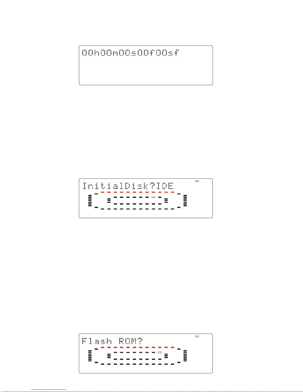
4-8. Flash ROM
This mode is used when copying the system software from EPROMs to Flash ROM. As mentioned in the section “3.
SOFTWARE UPDATE” (page 11), the D1624/D824 software inside the Flash ROM can be updated through the SCSI
port. However, if something wrong happens when updating the software (e.g. A blackout occurred while updating the
software.), the D1624/D824 might not be able to boot up using the system software inside the Flash ROM.
In this case, the following procedures must be taken.
1. Turn off the power of D1624/D824 and disconnect the AC cable from the AC IN socket.
2. Plug the D1624/D824 EPROMs into the ROM CARD PCB assy sockets (U1 and U2). The SW on the ROM
CARD PCB assy must be set to “EPROM” side.
3. Open up the top cover, loosen 4 screws fixing the HD bay to the HD bracket and move the bay to the front side,
so that the ROM CARD PCB assy can be plugged into the 50-pin connector J5 on the MAIN PCB assy vertically.
4. Connect the AC cable and turn on the power of D1624/D824.
In this condition, the D1624/D824 is booted up using the system software inside the EPROMs. The next procedures to
take are as follows.
4-7. Initializing Disk
This is the mode to initializes a 3.5” internal E-IDE hard disk drive or an external SCSI device connected to the SCSI
port.
CAUTION: If both the external SCSI drive and the internal 3.5” E-IDE hard disk drive are connected at the same time,
currently selected drive by the SETUP menu “Drive_Sel?” will be initialized.
After pressing the [EXECUTE/YES] key, “SURE?” will start blinking on the FL display. In this condition, pressing
the [EXECUTE/YES] key one more time would initialize the recognized disk drive. This mode puts the disk back to
the condition originally formatted. This mode is exclusively designed for our manufacturer. To initialize the disk, use
the ERASE function in the Format SETUP menu.
44.1kHz
42
∞
_
OL
0
30
24
18
12
9
6
3
1234567891011 12 13 14 15 16
: Blinking
44.1kHz
OFFSET
42
∞
_
OL
0
30
24
18
12
9
6
3
12345678910111213141516
In order to check the offset value, select the “MTC” time base and the “REMAINING TIME” display. The display
below is an example of offset display. This mode is identical to the one when the normal SETUP menu “Offset Disp?”
is selected.
This manual suits for next models
5
Table of contents
Other Fostex Voice Recorder manuals

Fostex
Fostex D-15 User manual

Fostex
Fostex D-25 User manual

Fostex
Fostex DP-8 User manual

Fostex
Fostex D-108 Owner's manual

Fostex
Fostex FR-2 User manual

Fostex
Fostex VF-160 User manual

Fostex
Fostex MR-8 MKII User manual

Fostex
Fostex VF80 User manual

Fostex
Fostex VF80 User manual

Fostex
Fostex D-10 User manual

Fostex
Fostex D-25 User manual

Fostex
Fostex D2424LV MKII User guide

Fostex
Fostex D-20B User manual

Fostex
Fostex D2424LVMKII User guide

Fostex
Fostex XR-5 User manual

Fostex
Fostex PD-2 User manual

Fostex
Fostex MR-8HD/CD User manual

Fostex
Fostex GT10 User manual

Fostex
Fostex D-160 User manual

Fostex
Fostex D-160 User manual


 operating instructions")


