Issue Date: 4-19-02 Rev. Date: 12-21-05 Rev. Level: 12 OIPM P/N 3420458
Page 10 of 24
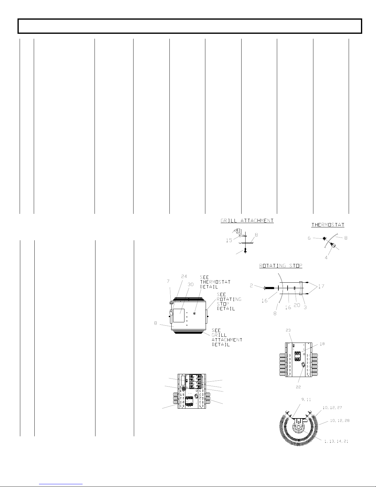
Ref
No.
Description 1024-1CA 1520-3A 1524-3E 1548-3E 1560-3A 3048-3A 3060-3A
1 Motor 8482001 (1) 8482001 (1) 8482001 (1) 8482002 (1) 8482003 (1) 8482004 (1) 8482005 (1)
2 Bolt carriage ½-13 x 2-3/4 2470132 (2) 2470132 (2) 2470132 (2) 2470132 (2) 2470132 (2) 2470132 (2) 2470132 (2)
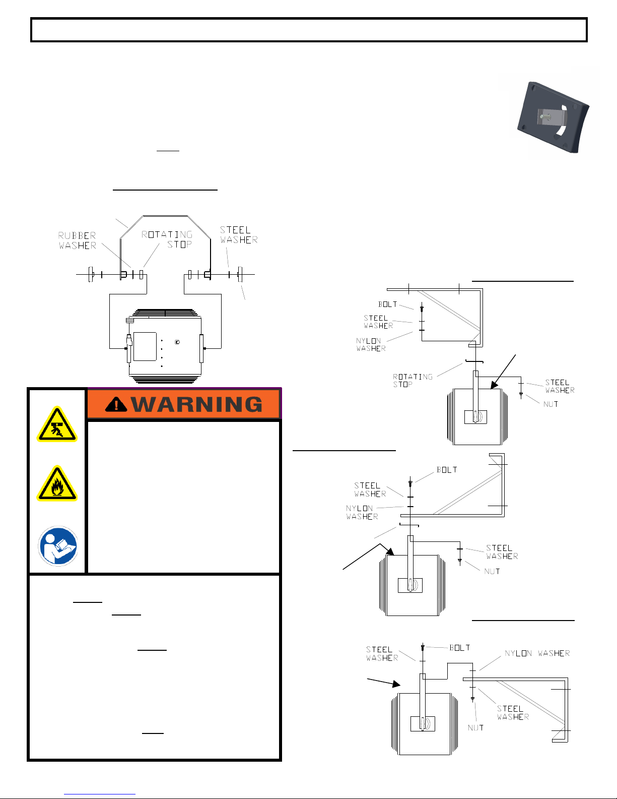
3 Rotating stop 8481223 (2) 8481223 (2) 8481223 (2) 8481223 (2) 8481223 (2) 8481223 (2) 8481223 (2)
4 Thermostat 2470300 (1) 2470300 (1) 2470300 (1) 2470300 (1) 2470300 (1) 2470300 (1) 2470300 (1)
5 Washer Reducing (not
shown) N/A N/A N/A 2485400 (2) 2485400 (2) N/A N/A
6 Knob thermostat 2470500 (1) 2470500 (1) 2470500 (1) 2470500 (1) 2470500 (1) 2470500 (1) 2470500 (1)
7 Strap 2470800 (1) 2470800 (1) 2470800 (1) 2470800 (1) 2470800 (1) 2470800 (1) 2470800 (1)
8 Shroud 8480 10 (1) 8480 10 (1) 8480 10 (1) 8480 10 (1) 8480 10 (1) 8481110 (1) 8481110 (1)
Motor mount bracket 8480801 (1) 8480801 (1) 8480801 (1) 8480801 (1) 8480801 (1) 8480800 (1) 8480800 (1)
10 Screw 10-32x 5/16 SEMS 2470 32 (8) 2470 32 (12) 2470 32 (12) 2470 32 (12) 2470 32 (12) 2470 32 (24) 2470 32 (24)
11 Mount motor end 8480700 (2) 8480700 (2) 8480700 (2) 8480700 (2) 8480700 (2) 8480700 (2) 8480700 (2)
12 Washer /16 341 500 (8) 341 500 (12) 341 500 (12) 341 500 (12) 341 500 (12) 341 500 (24) 341 500 (24)
13 Nut hex ¼-20 3426000 (4) 3426000 (4) 3426000 (4) 3426000 (4) 3426000 (4) 3426000 (4) 3426000 (4)
14 Washer ¼ 3427 00 (8) 3427 00 (8) 3427 00 (8) 3427 00 (8) 3427 00 (8) 3427 00 (8) 3427 00 (8)
15 Grill 8480621 (2) 8480621 (2) 8480621 (2) 8480621 (2) 8480621 (2) 8480621 (2) 8480621 (2)
16 Washer 2472032 (4) 2472032 (4) 2472032 (4) 2472032 (4) 2472032 (4) 2472032 (4) 2472032 (4)
17 Screw 8-18 x ½ 3444456 3444456 3444456 3444456 3444456 3444456 3444456
18 Contactor 8480402 (1) 8480402 (1) 8480400 (1) 8480401 (1) 8480403 (1) 8480401 (1) 8480403 (1)
1 Cordset – not shown 3171701 (1) ------
------ ------ ------ ------ ------
20 Nut ½-13 3460200 (2) 3460200 (2) 3460200 (2) 3460200 (2) 3460200 (2) 3460200 (2) 3460200 (2)
21 Screw ¼-20 x ¾ 34 4156 (4) 34 4156 (4) 34 4156 (4) 34 4156 (4) 34 4156 (4) 34 4156 (4) 34 4156 (4)
22 Over temperature switch 3183 00 (1) 3183 00 (1) 3183 00 (1) 3183 00 (1) 3183 00 (1) 41041001 (1) 41041001 (1)
23 Ground Lug 41254001 (1) 41254001 (1) 41254001 (1) 41254001 (1) 41254001 (1) 41254001 (1) 41254001 (1)
24 Connector 7714122 (1) 7714122 (1) 7714122 (1) 2485300 (1) 2485300 (1) 7714122 (1) 7714122 (1)
25 Baffle – not shown 8483800 (1) 8483800 (1) 8483800 (1) 8483800 (1) 8483800 (1) 8483800 (1) 8483800 (1)
26 Bussbar – not shown 8421600 (4) 8421600 (8) 8421600 (8) 8421600 (5) 8421600 (5) 8421600 (10) 8421600 (10)
27 Element inner 8481401 (2) 8481403 (3) 8481401 (3) 8481401 (3) 8481405 (3) 8481401 (6) 8481405 (6)
28 Element outer 8481402 (2) 8481404 (3) 8481402 (3) 8481402 (3) 8481406 (3) 8481402 (6) 8481406 (6)
2
30
Blade fan – not shown
Cover
8422300 (1)
8481010 (1)
8422300 (1)
8481010 (1)
8422300 (1)
8481010 (1)
8422300 (1)
8481010 (1)
8422300 (1)
8481010 (1)
8422300 (1)
8481010 (1)
8422300 (1)
8481010 (1)
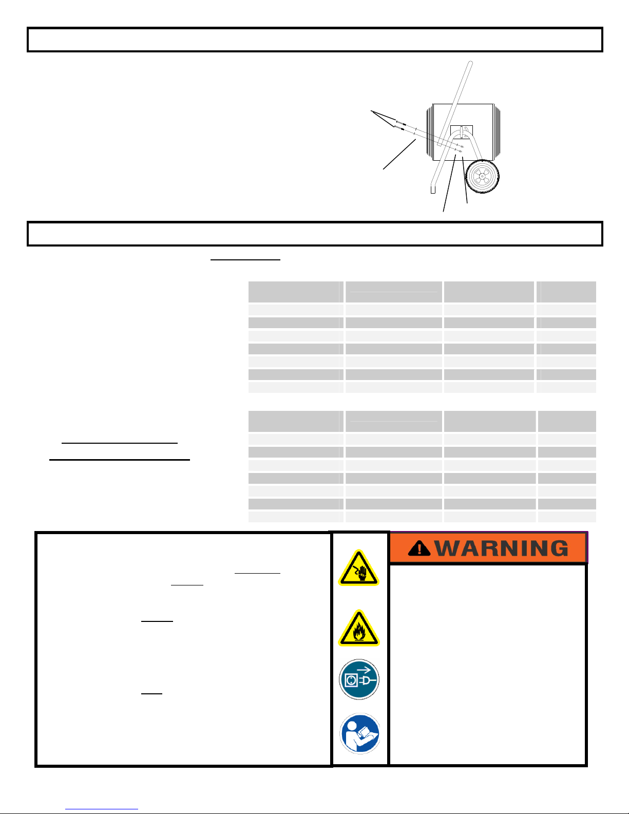
5
43
44
23
22
34
45
38
Ref
No.
Description 1524-1A
1 Motor 8482001 (1)
2 Bolt carriage ½-13 x 2-3/4 2470132 (2)
3 Rotating stop 8481223 (2)
4 Thermostat 2470300 (1)
5 Washer reducing (not
shown) N/A
6 Knob thermostat 2470500 (1)
7 Strap 2470800 (1)
8 Shroud 8481110 (1)
Motor mount bracket 8480800 (1)
10 Screw 10-32x 5/16 SEMS 2470 32 (12)
11 Mount motor end 8480700 (2)
12 Washer /16 341 500 (12)
13 Nut hex ¼-20 3426000 (4)
14 Washer ¼ 3427 00 (10)
15 Grill 8480621 (2)
16 Washer 2472032 (4)
17 Screw 8-18 x ½ 3444456
18 Contactor 8480406 (1)
1
20 Nut ½-13 3460200 (2)
21 Screw ¼-20 x ¾ 34 4156 (4)
22 Over temperature switch 3183 00 (1)
23 Ground Lug 41254001 (1)
24 Connector 7714122 (1)
25 Baffle-not shown 8483800 (1)
26 Bussbar – not shown 8421600 (8)
27 Element inner 8481401 (3)
28 Element outer 8481402 (3)
2 Blade fan – not shown 8422300 (1)
30 Cover 8481010 (1)
31 Bracket fuse block 8481700 (1)
32 Fuse block 8481600 (2)
33
34
Fuse type FLNR-40 250V
Terminal block
71031471 (4)
51243002 (1)
FES REPLACEMENT PARTS LIST& EXPLODED VIEWS
17