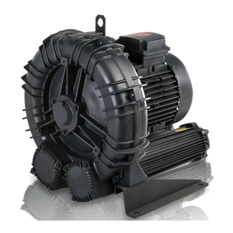
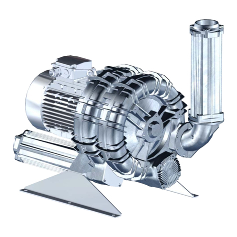
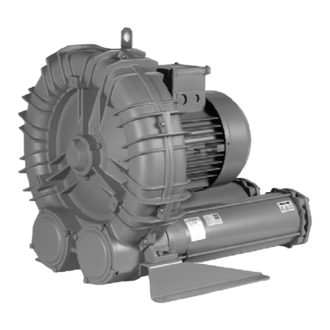
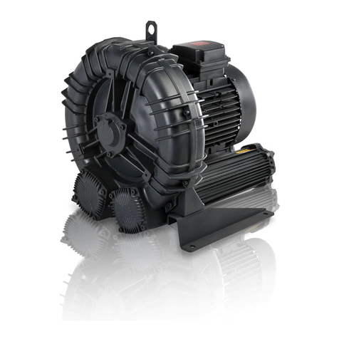
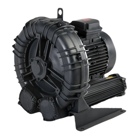
FPZ SCL TS Series User manual

FPZ S.p.A.
Via F.lli Cervi 16
20863 Concorezzo (MB), ITALIA
Tel. +39 039 69098 1
FPZ-MI-K TS-MOR-USA-15-R03
PLEASE READ CAREFULLY ALL INSTRUCTIONS AND KEEP THEM FOR FUTURE
REFERENCE
EN
SIRVASE LEER CUIDADOSAMENTE TODAS LAS INSTRUCCIONES Y
CONSERVARLAS PARA FUTURA REFERENCIA
ES
LIRE ATTENTIVEMENT TOUTES LES INSTRUCTIONS ET LES CONSERVER
FR
LEGGERE ATTENTAMENTE TUTTE LE ISTRUZIONI E CONSERVARLE
IT
SCL K05 / K06 / K07 / K08 / K09 / K10 / K11 / K12
TS-MOR
LATERAL CHANNEL BLOWERS-EXHAUSTERS
INSTRUCTIONS
EN
COMPRESORES – ASPIRADORES DE CANAL LATERAL
INSTRUCCIONES
ES
COMPRESSEURS – ASPIRATEURS A CANAL LATERAL
INSTRUCTIONS
FR
COMPRESSORI-ASPIRATORI A CANALE LATERALE
ISTRUZIONI
IT

FPZ-MI-K TS-MOR-USA-15-R03 2 / 79

FPZ-MI-K TS-MOR-USA-15-R03 3 / 79

FPZ-MI-K TS-MOR-USA-15-R03 4 / 79
COMPRESSION
PERFORMANCE TABLE
EN
1COMPRESIÓN
DATOS CARACTERÍSTICOS
ES
COMPRESSION
CARACTÉRISTIQUES TECHNIQUES
FR
23COMPRESSIONE
DATI CARATTERISTICI
IT
Model N
3500 rpm
[HP]
N
2900 rpm
[HP]
Q max
3500 rpm
[cfm]
Q max
2900 rpm
[cfm]
ΔP max
3500 rpm
[In WG]
ΔP max
2900 rpm
[In WG]
Leq¹
3500 rpm
(Lp) [dB(A)]
Leq¹
2900 rpm
(Lp) [dB(A)]
Weight²
max
[Lbs]
K05-TS
3
3
290
240
30
45
72
70
85.98
4
4
290
240
46
70
73.5
71.5
89.29
5.5
5.5
290
240
72
100
75.5
73.5
93.7
K06-TS
5.5
5.5
399
331
36
55
77.2
75.2
104.72
7.5
7.5
399
331
55
65
77.5
75.5
141.09
10
10
399
331
85
93
77.8
75.8
149.91
K07-TS
7.5
7.5
587
486
36
48
83.9
81.9
197.31
10
10
587
486
60
71
84.2
82.2
206.13
15
15
587
486
110
121
84.8
82.8
223.77
K08-TS
7.5
7.5
715
592
18
30
80.8
78.8
205.47
10
10
715
592
37
50
80.9
78.9
214.29
15
15
715
592
75
87
83.3
81.3
231.92
K09-TS
15
15
941
780
52
62
83
81
270.06
20
20
941
780
80
90
85
83
350.53
25
25
941
780
110
120
87
85
383.6
K10-TS
15
15
1093
905
41
51
87.8
85.8
274.47
20
20
1093
905
65
75
88.1
86.1
354.94
25
25
1093
905
80
95
88.4
86.4
388.01
K11-TS
25
25
1253
1038
50
69
89.4
87.4
429.02
30(*)
30
1253
1038
70
90
90
88
434.53
K12-TS
30
30
1410
1168
45
80
90.6
88.6
436.75
(*)K11-TS 30HP vertical assembly only, K11-TS 30HP montaje solo en posicion vertical, K11-TS, 30HP positionnement en vertical seulement, K11-TS 30HP montabile solo in
posizione verticale
1Noise measured at 1 m distance with inlet and outlet ports piped, in accordance to ISO 3744
Rumorosidad medida a 1 m de distancia de los puertos de admisión y descarga, según la Normativa ISO 3744.
Niveau de bruit mesuré a 1 m de distance, conduits d’aspiration et refoulement raccordés selon la norme ISO 3744
Rumorosità misurata alla distanza di 1 m con aspirazione e mandata canalizzate, secondo la Normativa ISO 3744
2Value refers to the weight of the machine with 3 Phase motor if MOR range, without motor if GOR or GVR range.
El valor indicado se refiere al equipo con motor trifásico para la ejecución MOR. Sin el motor eléctrico para las ejecuciones GOR y GVR.
Le valeur se refère à la turbine 3-phasé en execution MOR et GOR/GVR pour la turbine sans moteur.
Il valore indicato è riferito alla macchina con motore trifase per esecuzione MOR, senza il motore elettrico per esecuzioni GOR e GVR.
N: Installed motor power
Q: Flow rate
ΔP: Differential pressure
Leq: Noise
Ps max A: Maximum absolute pressure
N: Potencia instalada
Q: Caudal
ΔP: Presión diferencial
Leq: Rumorosidad
Ps max A: Pressão máxima absoluta
N: Puissance installé
Q: Débit
ΔP: Pression différentielle
Leq: Niveau sonore
Ps max A: Pression absolute maxi
N: Potencia instalada
Q: Caudal
ΔP: Presión diferencial
Leq: Rumorosidad
Ps max A: Pressão máxima absoluta

FPZ-MI-K TS-MOR-USA-15-R03 5 / 79
ASPIRATION
PERFORMANCE TABLE
EN
ASPIRACIÓN
DATOS CARACTERÍSTICOS
ES
ASPIRATION
CARACTÉRISTIQUES TECHNIQUES
FR
ASPIRAZIONE
DATI CARATTERISTICI
IT
Model N
3500 rpm
[HP]
N
2900 rpm
[HP]
Q max
3500 rpm
[cfm]
Q max
2900 rpm
[cfm]
ΔP max
3500 rpm
[In Hg]
ΔP max
2900 rpm
[In Hg]
Leq¹
3500 rpm
(Lp) [dB(A)]
Leq¹
2900 rpm
(Lp) [dB(A)]
Weight²
max
[Lbs]
K05-TS
3
3
290
240
2.2
3.3
71.6
69.6
85.98
4
4
290
240
3.4
5.1
73.1
71.1
89.29
5.5
5.5
290
240
5.3
6.6
75.1
73.1
93.7
K06-TS
5.5
5.5
399
331
2.7
4
76.8
74.8
104.72
7.5
7.5
399
331
4
4.8
77.1
75.1
141.09
10
10
399
331
6.3
6.8
77.4
75.4
149.91
K07-TS
7.5
7.5
587
486
2.6
3.5
84.5
82.5
197.31
10
10
587
486
4.4
5.2
84.8
82.8
206.13
15
15
587
486
8.1
8.9
85.4
83.4
223.77
K08-TS
7.5
7.5
715
592
1.3
2.2
80.9
78.9
205.47
10
10
715
592
2.7
3.7
81.2
79.2
214.29
15
15
715
592
5.5
6.4
82.9
80.9
231.92
K09-TS
15
15
941
780
3.8
4.5
82.2
80.2
270.06
20
20
941
780
5.9
6.6
84.1
82.1
350.53
25
25
941
780
8.1
8.8
86.1
84.1
383.6
K10-TS
15
15
1093
905
3
3.6
89.1
87.1
274.47
20
20
1093
905
4.8
5.5
89.4
87.4
354.94
25
25
1093
905
5.9
7
89.7
87.7
388.01
K11-TS
25
25
1253
1038
3.7
5
90.7
88.7
429.02
30(*)
30
1253
1038
5.1
6.6
91.3
89.3
434.53
K12-TS
30
30
1410
1168
3.3
5.9
91.9
89.9
436.75
(*)K11-TS 30HP vertical assembly only, K11-TS 30HP montaje solo en posicion vertical, K11-TS, 30HP positionnement en vertical seulement, K11-TS 30HP montabile solo in
posizione verticale
1Noise measured at 1 m distance with inlet and outlet ports piped, in accordance to ISO 3744
Rumorosidad medida a 1 m de distancia de los puertos de admisión y descarga, según la Normativa ISO 3744.
Niveau de bruit mesuré a 1 m de distance, conduits d’aspiration et refoulement raccordés selon la norme ISO 3744
Rumorosità misurata alla distanza di 1 m con aspirazione e mandata canalizzate, secondo la Normativa ISO 3744
2Value refers to the weight of the machine with 3 Phase motor if MOR range, without motor if GOR or GVR range.
El valor indicado se refiere al equipo con motor trifásico para la ejecución MOR. Sin el motor eléctrico para las ejecuciones GOR y GVR.
Le valeur se refère à la turbine 3-phasé en execution MOR et GOR/GVR pour la turbine sans moteur.
El valor indicado se refiere al equipo con motor trifásico para la ejecución MOR. Sin el motor eléctrico para las ejecuciones GOR y GVR
N: Installed motor power
Q: Flow rate
ΔP: Differential pressure
Leq: Noise
Ps max A: Maximum absolute pressure
N: Potencia instalada
Q: Caudal
ΔP: Presión diferencial
Leq: Rumorosidad
Ps max A: Pressão máxima absoluta
N: Puissance installé
Q: Débit
ΔP: Pression différentielle
Leq: Niveau sonore
Ps max A: Pression absolute maxi
N: Potenza installata
Q: Portata
ΔP: Pressione differenziale
Leq: Rumorosità
Ps max A: Pressione max assoluta

FPZ-MI-K TS-MOR-USA-15-R03 6 / 79
DIMENSIONS
( K05-TS / K06-TS/ K07-TS / K08-TS / K09-TS / K10-TS / K11-TS / K12-TS )
DIMENSIONES
DIMENSIONS
DIMENSIONI
Dimensions in in, Medidas in In, Dimensions en In, Dimensioni in In
Model
a
b
c
d
e
f
G
H
K05-TS
12.87
16.61
10.16
3.03
15.91
14.72
3" NPT
18.64
K06-TS
14.80
17.72
10.31
2.95
15.91
14.72
3" NPT
22.60
K07-TS
16.69
20.91
12.56
3.86
18.43
17.24
4" NPT
24.55
K08-TS
17.99
21.57
12.56
3.86
18.82
17.64
4" NPT
24.55
K09-TS
19.37
24.02
14.37
4.41
20.00
18.82
5.12
30.79
K10-TS
20.31
24.53
14.37
4.41
20.00
18.82
5.12
30.79
K11-TS
21.34
25.59
14.96
4.17
21.26
20.08
5.12
31.38
K12-TS
21.57
25.67
14.96
4.17
21.26
20.08
5.12
31.50
Model
i
k
m
n
o
p1
p2
K05-TS
5.91
-
0.51
11.81
13.58
24.96
9.80
K06-TS
6.10
-
0.51
11.81
13.58
26.06
10.55
K07-TS
7.17
-
0.51
9.84
21.65
31.57
12.40
K08-TS
7.17
-
0.51
9.84
21.65
31.57
12.40
K09-TS
8.27
8.27
0.51
9.84
21.65
33.46
17.60
K10-TS
8.27
8.27
0.51
9.84
21.65
33.46
17.60
K11-TS
8.98
8.27
0.51
9.84
21.65
34.25
18.19
K12-TS
8.98
8.27
0.51
9.84
21.65
34.37
18.19
Model
q
r
s
t
u
v
w
x
z
K05-TS
0.98
12.91
0.16
M8
7.87
17.17
18.94
6.93
0.75
K06-TS
0.98
13.19
0.16
M8
9.45
17.91
18.94
7.68
0.75
K07-TS
0.98
11.77
0.20
M8
11.61
20.55
22.87
10.87
0.63
K08-TS
0.98
11.77
0.20
M8
12.20
20.55
22.87
10.87
0.63
K09-TS
-
12.40
0.20
M8
14.17
21.97
23.94
13.27
0.63
K10-TS
-
12.40
0.20
M8
14.17
21.97
23.94
13.27
0.63
K11-TS
-
12.60
0.20
M8
15.35
22.56
23.94
13.86
0.63
K12-TS
-
12.60
0.20
M8
15.35
22.56
23.94
13.86
0.63

FPZ-MI-K TS-MOR-USA-15-R03 7 / 79
REPOSITIONING OF SILENCERS
( K05-TS / K06-TS / K07-TS / K08-TS / K09 / K10 –TS / K11-TS/ K12-TS)
COLOCACIÓN DE LOS SILENCIADORES
REPOSITIONNEMENT DES SILENCIEUX
RIPOSIZIONAMENTO SILENZIATORE
Ver. 0
Ver. 0-A
Ver. 1
Ver. 2
Ver. 3 - Ver 3 90°D/90°S
Ver. 4 - 90°D
Ver. 4 - 90° S

FPZ-MI-K TS-MOR-USA-15-R03 8 / 79
INSTALLATION DIAGRAM
EN
ESQUEMA DE INSTALACIÓN
ES
SCHÉMA D'INSTALLATION
FR
SCHEMI DI INSALLAZIONE
IT
PRESSURE SERVICE
COMPRESOR
SOUFFLANTE
COMPRESSORE
SERIES PRESSURE SERVICE
COMPRESOR EN SERIE
SOUFFLANTE EN SÉRIE
COMPRESSORE IN SERIE
PARALLEL PRESSURE SERVICE
COMPRESOR EN PARALELO
SOUFFLANTE EN PARALLÉLE
COMPRESSORE IN PARALLELO
VACUUM SERVICE
ASPIRADOR
POMPE À VIDE
ASPIRATORE

FPZ-MI-K TS-MOR-USA-15-R03 9 / 79
PARALLEL VAACUM SERVICE
ASPIRADOR EN PARALELO
POMPE À VIDE EN PARALLÈLE
ASPIRATORE IN PARALLELO
KEY – ACCESSORIES, TABLA DE ACCESORIOS, LÉGENDE ACCESSOIRES, LEGENDA
Item
Composant
Name
Denominación
Désignation
Denominazione
Item
Name
Denominación
Désignation
Denominazione
1
Filter - Inline filter
Filtro - Filtro en línea
Filtre - Filtre en ligne
Filtro - Filtro in linea
7
Check valve
Válvula de retención
Clapet anti-retour
Valvola di ritegno
(2)
Silencer
Silenciador
Silencieux
Silenziatore
8
Valve
Válvula
Vanne
Valvola
3
Flexible sleeve
Manguito flexible
Manchon flexible
Manicotto flessibile
(9)
Cooler
Intercambiador
Échangeur
Scambiatore
4
Pressure gauge - Vacuum gauge
Manómetro – Vacuómetro
Manomètre – Vacuomètre
Manometro – Vuotometro
(10)
Thermometer
Termómetro
Thermomètre
Termometro
5
Pressure switch – Vacuum switch
Presostato – Vacuóstato
Pressostat – Vacuostat
Pressostato – Vuotostato
(11)
Thermostat
Termostato
Thermostat
Termostato
6
Pressure relief valve
Válvula limitadora
Soupape de limitation
Valvola limitatrice
(x) IF NECESSARY
(x) SI NECESARIO
(x) SI NÉCESSAIRE
(x) SE NECESSARIO

FPZ S.p.A.
Via F.lli Cervi 16
20863 Concorezzo (MB), ITALIA
Tel. +39 039 69068 1
FPZ-MI-K TS-MOR-USA-15-R03
1GENERAL INFORMATION .............................................................................................................................................................11
PURPOSE OF THE MANUAL..................................................................................................................................................111.1
UNIT AND MANUFACTURER'S IDENTIFICATION .................................................................................................................111.2
TESTING, WARRANTY AND LIABILITY..................................................................................................................................111.3
2SAFETY RULES .............................................................................................................................................................................12
GENERAL NOTES ON SAFETY AND FOR THE USER..........................................................................................................122.1
CONDITIONS OF INSTALLATION AND NORMAL OPERATION ............................................................................................122.2
FAULT CONDITION AND MAINTENANCE..............................................................................................................................132.3
RESIDUAL RISKS...................................................................................................................................................................132.4
3FORESEEN USE............................................................................................................................................................................14
CONDITIONS OF USE............................................................................................................................................................143.1
SPECIAL VERSIONS..............................................................................................................................................................153.2
PROHIBITIONS.......................................................................................................................................................................153.3
REASONABLY FORESEEABLE IMPROPER USE..................................................................................................................153.4
4STORAGE AND TRANSPORT........................................................................................................................................................16
RECEPTION AND CHECK OF CONTENTS............................................................................................................................164.1
PACKING ................................................................................................................................................................................164.2
TRANSPORT AND HANDLING...............................................................................................................................................174.3
STORAGE...............................................................................................................................................................................174.4
5INSTALLATION...............................................................................................................................................................................17
INSTALLATION CONDITIONS................................................................................................................................................175.1
HORIZONTAL INSTALLATION................................................................................................................................................195.2
INSTRUCTIONS FOR REPOSITIONING SILENCER HOUSINGS ..........................................................................................195.3
5.3.1 90° MANIFOLD (accessory) USE...................................................................................................................................20
VERTICAL INSTALLATION ON THE COVER .........................................................................................................................205.4
ELECTRIC MOTOR.................................................................................................................................................................205.5
5.5.1 CONNECTION...............................................................................................................................................................21
5.5.2 INVERTER POWERED ELECTRIC MOTOR .................................................................................................................21
5.5.3 ROTATION DIRECTION................................................................................................................................................21
6STARTUP .......................................................................................................................................................................................22
PRELIMINARY CHECKS.........................................................................................................................................................226.1
OPERATION............................................................................................................................................................................226.2
STOPPING..............................................................................................................................................................................226.3
7MAINTENANCE..............................................................................................................................................................................23
PERIODICAL CHECKS ...........................................................................................................................................................237.1
PERIODICAL MAINTENANCE AND TROUBLESHOOTING....................................................................................................247.2
REPLACING THE SOUND ABSORBING MATERIAL..............................................................................................................247.3
LIFE OF BEARINGS................................................................................................................................................................257.4
OPERATION PROBLEMS.......................................................................................................................................................257.5
FPZ-MI-K TS-MOR-USA-15-R03 11 / 79
1GENERAL INFORMATION
PURPOSE OF THE MANUAL1.1
•The purpose of the manual is to provide the operator and maintenance personnel with "instructions for use" to prevent and
minimise risks during the interaction of man and unit.
•The information was prepared by the manufacturer in the original language (ITALIAN) according to the principles of professional
writing and in compliance with the applicable regulations.
•To facilitate its reading and understanding, the principles of communication best suited to the characteristics of the recipients have
been adopted as far as possible.
•Keep the manual and enclosed documentation for the entire service life of the unit in a known and easy to access place so that it is
always at hand for reference.
•To easily find specific information, see the table of contents.
•Any observations made by recipients can be an important contribution to improving the after-sales services provided by the
manufacturer.
•Some information may not entirely match the actual configuration of the work unit delivered.
•Some parts of the text, or those of considerable importance, are indicated by symbols, whose meaning is described:
These are generic or specific DANGER symbols and indicate hazards that can cause even serious accidents to
people if the required precautions are not taken.
This is the PROHIBITED symbol and indicates operations that must not be carried out because they can result in
even serious accidents to people.
ATTENTION
The word ATTENTION is used to provide additional information and in particular to point out hazards that can
cause
serious damage
.
NOTES FOR
THE USER
NOTES are used to provide information allowing the user to make best use of the unit, with best performance, and
for safety and respecting the environment.
UNIT AND MANUFACTURER'S IDENTIFICATION1.2
The nameplate gives all the unit's identification details, which should always appear in all correspondence between the user and
manufacturer.
The nameplate is placed on the machine:
TESTING, WARRANTY AND LIABILITY1.3
Testing and inspection
•The entire unit is sent to the customer prearranged for installation, after passing the tests and inspections required by the
manufacturer, in conformity with the applicable laws.
Warranty
•Warranties are defined in the general terms and conditions of sale.
Liability
•FPZ S.p.A. cannot be held liable for operation faults or generic failures caused by improper use of the unit or operations carried out
by persons not authorised by FPZ S.p.A.
It is strictly forbidden to remove or tamper
with the nameplate.

FPZ-MI-K TS-MOR-USA-15-R03 12 / 79
2SAFETY RULES
GENERAL NOTES ON SAFETY AND FOR THE USER2.1
•Do not start the unit until its operation is clearly understood.
•If any doubts arise, despite having read this manual carefully and completely, contact FPZ S.p.A.
•Make sure all personnel involved in the use of the unit are informed regarding the safety requirements.
•Before starting the unit, the operator must check the efficiency of the safety devices and for any obvious defects in the unit. In case
of any defects, immediately notify FPZ S.p.A.
•Check the proper operation of all the safety devices every day.
•The safety devices must never be removed or disabled.
•During maintenance or repair work it may be necessary to exclude some safety devices from the service. This operation must be
carried out by authorised personnel.
•Never attempt rash solutions.
•All installation, commissioning and maintenance operations must be carried out exclusively by qualified personnel.
•Do not modify the electrical connections on the unit.
•Do not wear clothes, jewellery or accessories that can get caught in moving parts.
•Always keep the area around the unit free of obstructions.
•Use appropriate PPE such as boots, gloves, goggles and work clothes.
•Pay attention to all danger and caution signs placed on the unit.
•Always apply and enforce the safety rules; in case of any doubts, always consult this manual before acting.
•The unit must be used only and exclusively for its intended purpose and in accordance with that contractually established with FPZ
S.p.A.
CONDITIONS OF INSTALLATION AND NORMAL OPERATION2.2
Startup and operation must occur only under the following conditions:
•The unit must be completely assembled and intact, i.e. not damaged or tampered with.
•The silencer must be properly connected to the system piping.
•The machine must be securely fixed in place.
•The motor must be connected to a suitable control panel.
•If installed outdoors, protect the unit against the sun and weather.
The instructions listed below must be read carefully and become a fundamental part of daily
procedures in the use and maintenance of all the equipment, in order to prevent any kind of
accident, injury or damage.
Non-compliance with the unit's intended use can cause serious accidents
The unit must only be started:
•In conformity with the purposes of use, transport and handling specified in "FORESEEN USE",
•respecting the values given in the "SPECIFICATIONS" and RATING DATA.
Risk of injury due to shearing, crushing, entanglement!
During work on the unit there are risks of injury due to shearing, crushing or entanglement!
Therefore it must be carried out by technicians who handle and install the machine, taking the necessary safety measures and
following the instructions given in this manual.
Danger due to escaping process fluids!
Danger due to overpressure with sudden release of process fluids (injury to the skin and eyes)!
Start the machine only if properly connected.
Danger due to electricity!
Improper behaviour can cause serious accidents!
Work on the electrical equipment must only be carried out by qualified and authorised electricians!
Before starting work on the unit or system, take the following precautions:
- disconnect the mains power;
- open the terminal box only after making sure the power is disconnected;
- take steps to prevent the power from being reconnected.

FPZ-MI-K TS-MOR-USA-15-R03 13 / 79
FAULT CONDITION AND MAINTENANCE2.3
Before starting routine maintenance on the unit, or for a fault, take the following safety measures:
•Disconnect the unit from the power supply via the main the switch.
•Place a sign: “DANGER! Maintenance work in progress." on the system control and the unit's control elements.
•Allow the unit to cool!
•Wait until the unit has completely stopped, i.e. that the impeller is not rotating, checking the electric motor fan.
•Ensure the absence of vacuum or overpressure in the unit and in the piping to be disconnected and that no fluid can escape from
the unit and/or system!
•Follow the maintenance instructions in this manual.
RESIDUAL RISKS2.4
When designing the machines or systems on which the blower is to be installed, the following residual risks must be considered.
Danger of suction!
Danger due to negative pressure: sudden drawing in of hair and clothing! Start the machine only if properly connected.
Danger due to seizing of the impeller caused by performance values being exceeded
Use the blower, making sure the operating conditions comply with the values given in the SPECIFICATIONS.
Never operate the unit even temporarily with the inlet and/or outlet port closed.
Install a pressure-relief valve or equivalent circuit that can prevent excessive vacuum and/or overpressure and that enables
compliance with the values given in the SPECIFICATIONS in this manual and the RATING DATA.
Turn the unit off immediately in case of any abnormal impeller noise! Then schedule maintenance.
Danger of burns caused by contact with hot surfaces of the unit!
In operation, in conformity with the values given in the "SPECIFICATIONS" and RATING DATA, the blowers / exhausters can reach
high surface temperatures.
Use suitable PPE against the risk of burns. (Also see the section residual risks.)
Danger due to rotating impellers: cutting or shearing.
The rotating impeller can be accessed through the openings of the body and cover of the machine, once the manifolds or blind
flanges are removed!
Never put hands or anything through these openings.
Danger due to electricity!
Improper behaviour can cause serious accidents!
Work on the electrical equipment must only be carried out by qualified and authorised electricians!
Before starting work on the unit or system, take the following precautions:
- disconnect the mains power;
- take steps to prevent the power from being reconnected;
- open the terminal box only after making sure the power is disconnected.
Danger due to hot surfaces!
In operation the unit may overheat, exposing the operator to contact with hot surfaces.
Do not touch the unit when in operation.
Before carrying out any operation after shutdown allow the unit to cool by waiting at least 20 minutes.
Danger due to rotating parts: electric motor cooling fan.
Although designed to reduce any danger, the machine has residual risks linked to the rotation of the fan.
Precautions to be taken:

FPZ-MI-K TS-MOR-USA-15-R03 14 / 79
0
1
2
3
4
5
6
7
8
9
10
11
12
13
65 70 75 80 85 90 95 100 105 110 115
reduction % of the outlet
pressure
ambient temperature °F
3FORESEEN USE
FPZ side channel blowers / exhausters are designed to generate vacuum and overpressure and for conveying non-explosive, non-
flammable, non-toxic and non-aggressive gases and air in continuous duty in a non-explosive environment.
FPZ side channel blowers / exhausters are designed and built for use in industrial plants and are equipped with three-phase or single-
phase asynchronous bipolar electric motors in compliance with IEC 60034-1.
CONDITIONS OF USE3.1
The maximum permissible pressure differentials given in the "SPECIFICATIONS” must never be exceeded. They are valid only under
the following conditions;
as a blower:
gas intake temperature 20°C (+68°F) and atmospheric pressure 1013 mbar (abs.) (29.92 In Hg ) measured at the inlet port
as an exhauster:
gas intake temperature 20°C (+68°F) measured at the inlet port and atmospheric backpressure 1013 mbar (abs.) (29.92 In
Hg).
The ambient temperature, and the conveyed gas intake temperature, is
permissible inside the range -15°C (+5°F) ÷ +40°C (+104°F) with the
following provisions;
•for ambient temperature +30°C (+86°F) reduce the maximum
pressure differentials given in the "SPECIFICATIONS” by 5%;
•for ambient temperature +40°C (+104°F) reduce the
maximum pressure differentials given in the
"SPECIFICATIONS” by 10%.
The graph to be used to reduce the maximum pressure differentials in
case of ambient temperature between +21°C and +40°C (+70°F and
+104°F) is given below
For installations above 1000m (3300ft) a.s.l.; contact the FPZ after-sales service
- Do not wear loose fitting clothes
- Do not go near the machine with long and loose hair
Danger due to noise from the unit!
Some machines can produce high noise levels, even exceeding 80 dB(A).
The reference values are given in the specifications, which do not consider environmental reverberation.
Precautions to be taken:
Check the actual sound pressure of the machine in the place, and if necessary:
- Report the foreseen noise risk
- Arrange the use of PPE
- Insulate the place
Non-compliance with the unit’s intended use can cause serious accidents.
•This manual:
MUST be read carefully and understood before carrying out any operations on the unit;
MUST be strictly complied with;
MUST always be at hand in the place where the unit is used.
•Installation must only be carried out by qualified personnel.
ATTENTION! If installation is outdoors, protect the unit from the sun.
ATTENTION! If the flow rate has to be reduced, use a bypass valve instead of throttling the suction or delivery.

FPZ-MI-K TS-MOR-USA-15-R03 15 / 79
•in case of suction in the place or on the system, protect the intake pipe using a suitable filter with maximum filtration of 25µm.
For the use of filters with filtration different from 25µm, ask FPZ. Check compliance with the maximum pressure / vacuum data
given in the SPECIFICATIONS (max ∆p).
•for use as a blower deduct the pressure loss (Pa) from the maximum compression indicated (max ∆P ), i.e. Pworking≈ max ∆P -
Pa(for Tambient=20°C and Pambient=1013 mbar)
•for use as an exhauster make sure the maximum vacuum at the inlet port is not exceeded.
SPECIAL VERSIONS3.2
FPZ side channel blowers/exhausters can be manufactured in special or custom versions; the instructions given in this manual still
apply to some of them.
The special versions manufactured, and for which that given above applies, are:
•BPA version
Machines built to work in harsh environments and/or for conveying aggressive fluids, where aggressive means the presence
of elements that can affect standard machine operation, such as humidity; as specified in point 2, conveying flammable,
explosive or toxic gases, or installation in potentially explosive places, is not permitted.
•TMS version
Machines that ensure mechanical seal between the parts that convey air or fluids, minimising leakage.
•Special electric motors
On request, blowers/exhausters can be manufactured with motors having one or more of the following characteristics:
-Special voltages
-Higher levels of protection against solid bodies and/or liquids (standard IP55)
-Higher insulation classes (standard Class F)
-Protection devices such as thermal switches, heaters, PTC, PT100
•Energy Efficient motors
The side channel blowers/exhausters can be manufactured using high efficiency, premium efficiency.
Further customisation must be requested and agreed when ordering, subject to a feasibility appraisal by the Technical Department.
PROHIBITIONS3.3
THE FOLLOWING IS STRICTLY PROHIBITED:
-Using the unit in installations for unforeseen use.
-The suction and conveying of aggressive, corrosive and/or harmful fluids.
-Using the unit in conditions different from the values given in the "SPECIFICATIONS" and RATING DATA.
-Using the unit without having installed the suction filter.
-Operation with inlet and/or outlet port closed.
-Making conversions or changes to the unit, maintenance or repair work
on own initiative or not envisaged in the manual.
Maintenance work can be carried out only in compliance with that described in this user manual, exclusively by qualified personnel.
IT IS COMPULSORY TO:
- Check and comply with the intended use of the machine.
- Check and comply with the conditions of use specified in this manual.
- Comply with the installation conditions specified in this manual.
- Carry out the preliminary checks as specified in the section "STARTUP".
- Carry out maintenance as specified in section 7.
REASONABLY FORESEEABLE IMPROPER USE3.4
•Listed below are some examples of improper use identified by risk analysis and practical experience, according to the conditions
they can create.
ATTENTION! For maintenance of special version machines, contact FPZ.
Non-compliance with the unit’s intended use can cause serious accidents.
Failure to comply with the prohibitions/obligations can result in technical faults, damage to the system or accidents.
Danger of serious injury!
IMPROPER USE
CONSEQUENCES
RISKS
IMPROPER USE LINKED TO NORMAL OPERATION
Failure to comply with the distance for the
motor air intake
Motor overheating and possible damage to
the blower
RISK FOR THE MACHINE
Presence of operators and possible contact
Operator coming into contact with hot parts
RISK FOR THE OPERATOR

FPZ-MI-K TS-MOR-USA-15-R03 16 / 79
4STORAGE AND TRANSPORT
RECEPTION AND CHECK OF CONTENTS4.1
•Upon receipt of the unit, check that the packaging is intact and without signs of damage
due to transport or storage conditions.
•If the packaging is damaged, immediately notify the forwarder and the manufacturer.
•Always check that the material received matches that specified in the consignment note.
PACKING4.2
Depending on its size and weight, the unit is packed in the following ways:
•in a single box;
•on wooden platform with cardboard covering;
•in a wooden crate;
with the machine
of the machine
Use of loose clothing or untied long hair
Possible catching or suction in the machine
or in the motor fan
RISK FOR THE OPERATOR
IMPROPER USE LINKED TO METHODS OF USE
Failure to comply with the operating
conditions (par. 2.2):
- Ambient temperature outside the limits
or incorrect
- Altitude above 1000 m (3300ft)
-
Failure to consider system and filter
pressure losses
Machine performance different from the data
given, possible motor faults and seizing of
the impeller
RISK FOR THE MACHINE
Failure to install the filter (for use with
suction in the place)
Particles entering the blower with seizing of
the impeller
RISK FOR THE MACHINE
Operation outside curve (P/Q)
(Pressure /Flow rate)
Machine performance different from the data
given, possible motor faults and seizing of
the impeller
RISK FOR THE MACHINE, SYSTEMS
AND OPERATORS
Rigid connection between the machine and
system
Abnormal vibrations for the machine and/or
system with possible seizing of the impeller.
RISK FOR THE MACHINE, SYSTEMS
AND OPERATORS
Use of the unit with current values not
corresponding to nominal
Possible overheating of the machine and
motor when powered by an inverter.
RISK FOR THE MACHINE
IMPROPER USE LINKED TO MAINTENANCE WORK
Failure to clean the filter
Seizing of the impeller
RISK FOR THE MACHINE
Failure to eliminate of layers of surface dust
Machine overheating
RISK FOR THE MACHINE, SYSTEMS
AND OPERATORS
FAULT CONDITIONS / EMERGENCY CONDITIONS
Not stopping the machine when making an
abnormal noise.
Damage with possible seizing of the
impeller, machine overheating and possible
motor damage.
RISK FOR THE MACHINE, SYSTEMS
AND OPERATORS
The wood of the platforms, pallets and crates can be reused or recycled in accordance with the current
laws in the country where the unit is installed. Other materials, such as cardboard, plastic or protective film,
must be disposed of in accordance with local regulations.

FPZ-MI-K TS-MOR-USA-15-R03 17 / 79
TRANSPORT AND HANDLING4.3
=== m < 25 kg (55lb) m > 25 kg (55lb) m > 25 kg (55lb)
STORAGE4.4
•Store the machine in a dry place, if possible keeping it in its packaging.
•Do not remove the protection from the openings.
5INSTALLATION
INSTALLATION CONDITIONS5.1
•Make sure the conditions of use as described in section 3 are complied with, then proceed with installation of the machine as
specified below.
Manual handling and transport are permitted only in accordance with the current applicable
regulations.

FPZ-MI-K TS-MOR-USA-15-R03 18 / 79
•The unit's support surface must be flat, sturdy,
stable and as level as possible.
•The unit must be installed on a structure that does not transmit
vibrations. Do not install the unit on structures that can transmit or
amplify the noise.
•Installation of the unit must always be done using vibration dampers.
•Installation of the unit must ensure that motor ventilation is not
impeded by obstacles placed in the immediate vicinity. Therefore, the
motor air intake must remain free, ensuring a distance of at least
50mm between the motor fan cover and any structure.
•Connect the pipes using flexible sleeves, without resting the weight of
the pipes on the unit, with the exception of a possible filter in case of
suction in the place.
•Determine the dimensions a, b, c to allow adequate space for
installation of the unit with its accessories (Dimensions available in the
first section).
Size the pipes and choose accessories that minimise pressure losses; therefore:
•do not fit pipes narrower than the ports of the machine.
•when installing several machines in parallel, suitably size the manifold and the main line.
•use large-radius curves and not elbows.
•do not install valves with a smaller flow than nominal and check valves with shutter opposed by spring (the check valve with
lowest pressure loss is the lightened non-return valve).
•when used for oxygenation, choose diffusers with low flow resistance (low pressure loss).
See INSTALLATION DIAGRAMS in the first section.
Danger due to limited visibility in the place where the unit is installed!
Make sure to always have the installed unit under control when carrying out any operation in the installation area.
The control elements must be placed so that the installed unit can be seen.
Danger due to vibration!
Regularly check the fixing of the unit to the support structure.
Excessive vibration of the unit can seriously damage the machine.
NOTE FOR THE USER The vibration dampers are not included but are available on request.
ATTENTION!
When installed outdoors, protect the unit
against the sun and weather.
To avoid overloads caused by pressure fluctuations, install a bypass pressure-relief valve on the suction
pipe in case of operation as an exhauster, and on the delivery when operating as a blower.
If the flow rate has to be reduced, use a bypass valve instead of throttling the suction or delivery.
Protect the suction pipe with a filter with max. degree of filtration 25µm. For the use of filters with filtration
different from 25µm, ask FPZ. Foreign bodies are: dust, sand, gravel, dirt in the pipes, cutting burrs and
shavings, welding slag and spatter, metal burrs and sealant residuals produced when connecting the pipes.
Change the filters regularly.
Danger due to foreign bodies and dirt entering the unit!
The ingress of even tiny foreign bodies causes serious damage to the unit with probable breakage of the impeller blades and the danger
of debris being thrown out!
2 in

FPZ-MI-K TS-MOR-USA-15-R03 19 / 79
HORIZONTAL INSTALLATION5.2
•Units supplied with standard set-up are ready to be installed in the horizontal position
by means of the feet.
•The feet have holes for fixing; use all the holes and choose the appropriate type of
screw.
•Remove the protection on the ports before checking the rotation direction and before
final connection.
•To connect the unit to the piping, remove the flanges from the silencer housings to
make the appropriate connections using flexible sleeves, thereby avoiding rigid
connections which can cause stress and harmful vibrations.
•Refit the flanges on the silencer housings complete with gaskets and tighten.
Check the motor rotation direction (see par. 5.5.3 ROTATION DIRECTION)
INSTRUCTIONS FOR REPOSITIONING SILENCER HOUSINGS5.3
•The SCL K MOR series has been designed for maximum flexibility in positioning the silencer housings in order to allow different
installation configurations.
•The blower is normally supplied with silencers positioned as shown in figure A.
•If this arrangement has to be changed, establish the required arrangement of the silencer housings.
See the diagram provided in the first section of this manual
•Remove and refit the housings and blind flanges according to the following diagram to obtain the desired configuration
Removing the blind flange (B)
•Place the unit horizontal, resting the feet on a flat and stable surface.
•Undo the screws and remove the blind flange and gasket
Removing the silencer housing (C)
•Undo the screws.
•Remove the silencer housing with gasket.
(C) K05 - K06 - K07 - K08 / TS (C) K09 – K10 – K11 – K12 / TS
(A)
(B) K05 - K06 / TS
(B) K07 - K08 - K09 - K10 - K11 - K12 / TS

FPZ-MI-K TS-MOR-USA-15-R03 20 / 79
5.3.1 90° MANIFOLD (accessory) USE
•For different connection configurations, use the 90° manifold installed
only on the cover openings.
•See the possible configurations as previously illustrated.
Fitting the 90° manifold
•Remove the silencer as previously described.
•Insert the gaskets between the cover and manifold.
•Tighten the respective screws
•Assemble the silencer by proceeding in reverse order.
See par. 5.1 for INSTALLATION CONDITIONS
VERTICAL INSTALLATION ON THE COVER5.4
The units can be installed with the working axis vertical, as follows:
•Using vibration dampers fitted directly on the cover, without manifold.(E)
•Using a special foot for vertical fixing, available as an accessory.(F)
ELECTRIC MOTOR5.5
Danger due to rotating parts: impeller!
The danger of shearing due to the rotating impeller can exist even when the machine off, if it is started manually.
Therefore use suitable work clothes and personal protection equipment.
NOTE FOR THE USER
The position of the silencer housing can be changed by using the manifold (on request).
See silencer housing repositioning diagrams in the first section.
Non-
compliance with the unit’s intended use can cause serious
injury.
Regularly check the fixing of the unit to the support structure.
Excessive vibration of the unit can seriously damage the machine.
ATTENTION!
Avoid the possibility of water stagnation, especially in case of
installation of the unit with vertical axis.
ATTENTION! Check the motor rotation direction. (see par. 5.5.3 ROTATION
DIRECTION)
NOTE FOR THE USER
A special foot is available as an accessory for fixing the unit vertically
on the cover. The foot has holes for fixing; use all the holes and
choose the appropriate type of screw.
NOTE FOR THE USER The vibration dampers are not included but are available on request.
Danger due to electricity!
•Improper behaviour can cause serious injury.
•Work on the electrical equipment (installation, maintenance) must only be carried out by qualified and authorised electricians!
•Before starting work on the unit or system, take the following precautions:
- make sure the machine is NOT powered;
- take steps to prevent the power from being reconnected;
- open the terminal box only after making sure the power is disconnected!
•The terminal box must not contain:
- foreign bodies;
- impurities;
- moisture.
E
F
This manual suits for next models
19
Table of contents
Languages:
Other FPZ Blower manuals

FPZ
FPZ SCL K-TD MOR Series User manual

FPZ
FPZ MOR EX2 User manual

FPZ
FPZ SCL K08R User manual

FPZ
FPZ SCL KO3-MS MOR User manual

FPZ
FPZ SCL K-MS MOR Series User manual

FPZ
FPZ SCL K07-MS MOR User manual

FPZ
FPZ SCL K04 TD-MOR User manual

FPZ
FPZ MOR EX3 User manual

FPZ
FPZ SCL K07R Quick guide

FPZ
FPZ MOR Series User manual