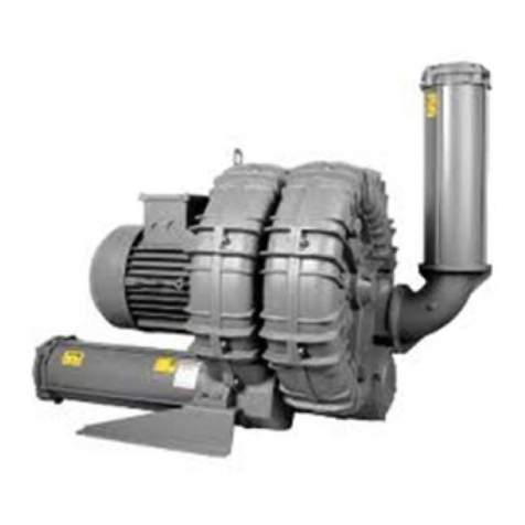
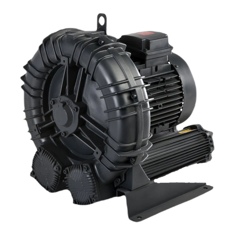
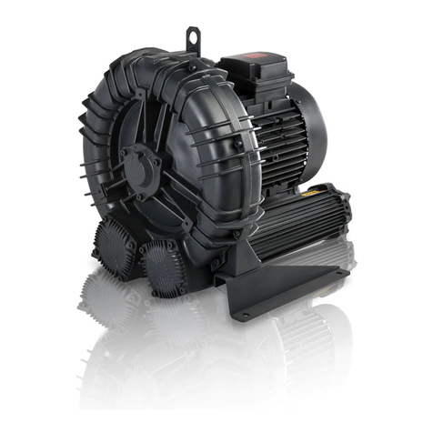
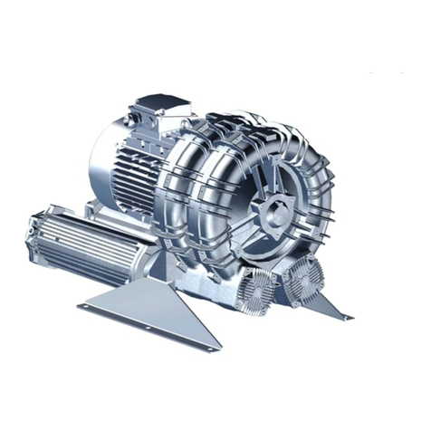
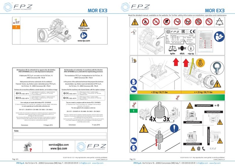
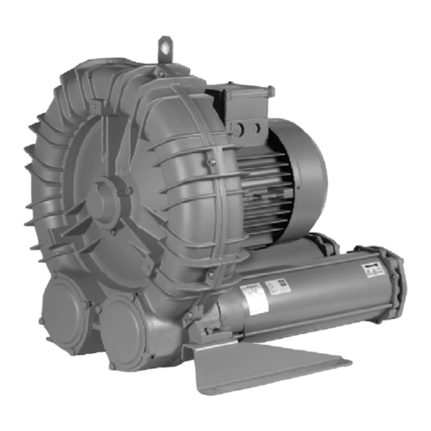
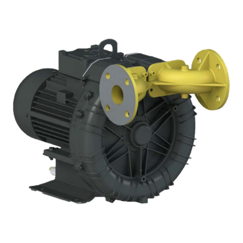
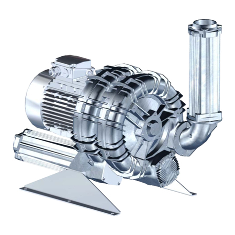
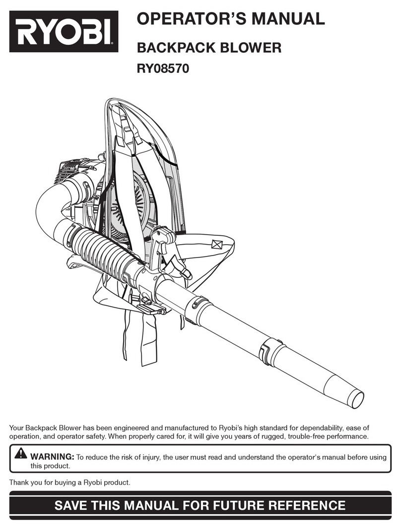
FPZ SCL K-MS MOR Series User manual

COMPRESSORI - ASPIRATORI A CANALE LATERALE ‘SCL K-MS MOR’ ISTRUZIONI I
LATERAL CHANNEL BLOWERS – EXHAUSTERS ‘SCL K-MS MOR’ INSTRUCTIONS GB
COMPRESSEURS - ASPIRATEURS A CANAL LATERAL ‘SCL K-MS MOR’ INSTRUCTIONS F
SEITENKANALVERDICHTER - VAKUUMPUMPEN BAUREIHE ‘SCL K-MS MOR’ BETRIEBSANLEITUNG D
COMPRESORES - ASPIRADORES DE CANAL LATERAL ‘SCL K-MS MOR’ INSTRUCCIONES E
LEGGERE ATTENTAMENTE TUTTE LE ISTRUZIONI E CONSERVARLE I
PLEASE READ CAREFULLY ALL INSTRUCTIONS AND KEEP THEM FOR FUTURE REFERENCE GB
LIRE ATTENTIVEMENT TOUTES LES INSTRUCTIONS ET LES CONSERVER F
ALLE ANLEITUNGEN SIND SORGFÄLTIG ZU LESEN UND AUFZUBEWAHREN! D
SIRVASE LEER CUIDADOSAMENTE TODAS LAS INSTRUCCIONES Y CONSERVARLAS PARA FUTURA REFERENCIA E
SN 1968-2
®
SCL K07 / K75 / K08 / K09 / K10 / K11
F.P.Z. effepizeta s.r.l.
Via F.lli Cervi 16/18
20049 Concorezzo - (MI) - ITALIA
Tel. +39 039 604 1820
Fax +39 039 604 1296
www.fpz.com

2/39
DICHIARAZIONE DI CONFORMITÁ ALLA DIRETTIVA MACCHINE
DECLARATION OF CONFORMITY TO THE MACHINERY DIRECTIVE
Unità tipo - Unit type
SCL K07-MS MOR - SCL K75-MS MOR - SCL K08-MS MOR
SCL K09-MS MOR - SCL K10-MS MOR - SCL K11-MS MOR
1. L’unità è in conformità con:
- DIRETTIVA MACCHINE CE 98/37;
- DIRETTIVA EMC CE 89/336 come modificata dalle Direttive CE 92/31 e CE 93/68;
- DIRETTIVA BASSA TENSIONE CE 73/23 come modificata dalla Direttiva CE 93/68.
È tuttavia vietata la messa in servizio prima che la macchina in cui sarà incorporata sia dichiarata
conforme con le citate Direttive.
2. Sottoposta a collaudo funzionale è risultata conforme alle caratteristiche richieste.
1. The unit conforms to the:
- MACHINERY DIRECTIVE CE 98/37;
- EMC DIRECTIVE CE 89/336 as ammended by the CE Directives 92/31 and 93/68;
- LOW VOLTAGE DIRECTIVE CE 73/23 as ammended by the CE Directive 93/68.
Nevertheless it is forbidden to put the unit in service before the machine in which will be incorporated
is declared in conformity with the above Directives.
2. The unit has been tested and meets its operating performances.
10.06
®

DATI CARATTERISTICI I
PERFORMANCE TABLE GB
CARACTÉRISTIQUES TECHNIQUES F
LEISTUNGDATEN D
DATOS CARACTERISTICOS E
Modello
Model
Modèle
Modell
Modelo
Potenza installata
Installed power
Puissance installé
Installierte Motorleistung
Potencia instalada
Pressione massima differenziale
Maximum differential pressure
Pression différentielle maxi
Druckdifferenz
Presión diferencial máxima
Rumorosità massima
Max noise level
Max niveau sonore
Max Schalldruckpegel
Rumorosidad máxima
Pressione massima assoluta
Maximum absolute pressure
Pression absolute maxi
Maximal absoluter druck
Presión absoluta máxima
Massa
Weight
Masse
Gewicht
Peso
kW hPa ( mbar ) Lp / Lw (1) dB (A) Ps max A M
50 Hz 60 Hz 50 Hz 60 Hz 50 Hz 60 Hz
2900 min-1 3500 min-1 2900 min-1 3500 min-1 2900 min-1 3500 min-1 MPa (bar) kg
2.2
2.55 - 130 / + 130 - 100 / + 100 76.4 78.4 0.28 (2.8) 46.5
3.0 3.45 - 200 / + 200 - 175 / + 175 76.7 78.7 0.28 (2.8) 47.5
4.0 4.6 - 280 / + 280 - 250 / + 250 77.0 79.0 0.28 (2.8) 51.0
5.5 6.3 - 325 / + 400 - 375 / + 375 77.3 79.3 0.28 (2.8) 61.5
SCL K07-MS
- 8.7 - / - - / + 450 - 79.6 0.28 (2.8) 66.5
4.0 4.6 - 150 / + 150 - 100 / + 100 77.4 79.4 0.28 (2.8) 51.5
5.5 6.3 - 250 / + 250 - 200 / + 200 77.7 79.7 0.28 (2.8) 62.0
7.5 8.7 - / + 325 - 300 / + 300 78.0 80.0 0.28 (2.8) 67.0
SCL K75-MS
9.2 10.6 - / - - / + 400 - 80.3 0.28 (2.8) 76.5
3.0 3.45 - 125 / + 125 - 100 / + 100 77.4 79.4 0.28 (2.8) 49.0
4.0 4.6 - 180 / + 180 - 150 / + 150 77.7 79.7 0.28 (2.8) 52.5
5.5 6.3 - 275 / + 275 - 250 / + 250 78.0 80.0 0.28 (2.8) 63.0
7.5 8.7 - 350 / + 400 - 375 / + 375 78.3 80.3 0.28 (2.8) 68.0
SCL K08-MS
9.2 10.6 - / + 450 - / + 450 78.6 80.6 0.28 (2.8) 77.5
4.0 4.6 - 130 / + 130 - 85 / + 85 78.0 80.0 0.28 (2.8) 62.0
5.5 6.3 - 210 / + 210 - 150 / + 150 78.2 80.2 0.28 (2.8) 72.5
7.5 8.7 - 290 / + 290 - 250 / + 250 78.5 80.5 0.28 (2.8) 77.5
9.2 10.6 - 350 / + 350 - 325 / + 325 78.7 80.7 0.28 (2.8) 87.0
11 12.7 - / + 450 - 375 / + 400 79.0 81.0 0.28 (2.8) 87.5
SCL K09-MS
- 17.4 - / - - / + 500 - 81.3 0.28 (2.8) 92.5
5.5 6.3 - 160 / + 160 - 115 / + 115 78.1 80.1 0.28 (2.8) 75.0
7.5 8.7 - 250 / + 250 - 200 / + 200 78.5 80.5 0.28 (2.8) 80.0
9.2 10.6 - 300 / + 300 - 270 / + 270 79.0 81.0 0.28 (2.8) 89.5
11 12.7 - 350 / + 400 - 375 / + 375 79.4 81.4 0.28 (2.8) 90.0
SCL K10-MS
15 17.4 - / + 500 - / + 500 79.6 81.6 0.28 (2.8) 95.0
5.5 - - 100 / + 100 - / - 78.5 - 0.28 (2.8) 78.5
7.5 8.7 - 175 / + 175 - 130 / + 130 80.0 82.0 0.28 (2.8) 83.5
9.2 10.6 - 230 / + 230 - 175 / + 175 80.5 82.5 0.28 (2.8) 93.0
11 12.7 - 300 / + 300 - 250 / + 250 81.0 83.0 0.28 (2.8) 93.5
15 17.4 - 350 / + 400 - 350 / + 350 81.8 83.8 0.28 (2.8) 98.5
SCL K11-MS
18.5 21.5 - / + 500 - / + 500 83.6 85.6 0.28 (2.8) 128.5
SI - Unità / Units / Unités / Einheiten / Unidades
(1) Rumorosità misurata alla distanza di 1 m con aspirazione e mandata canalizzate, secondo la Normativa ISO 3744.
(1) Noise measured at 1 m distance with inlet and outlet ports piped, in accordance to ISO 3744.
(1) Niveau de bruit mesuré a 1 m de distance, conduits d’aspiration et refoulement raccordés selon la norme ISO 3744.
(1) Schalldruckpegel, mit angeschlossener Schlauchleitung am Ein- und Auslass, im Abstand von 1 m gemäß ISO 3744 gemessen.
(1) Rumorosidad medida a la distancia de 1 m con vías de acceso de aspiración e impulsión canalizadas, según la Normativa ISO 3744.
3/39

DATI CARATTERISTICI I
PERFORMANCE TABLE GB
CARACTÉRISTIQUES TECHNIQUES F
LEISTUNGDATEN D
DATOS CARACTERISTICOS E
Modello
Model
Modèle
Modell
Modelo
Potenza installata
Installed power
Puissance installé
Installierte Motorleistung
Potencia instalada
Pressione massima differenziale
Maximum differential pressure
Pression différentielle maxi
Druckdifferenz
Presión diferencial máxima
Rumorosità massima
Max noise level
Max niveau sonore
Max Schalldruckpegel
Rumorosidad máxima
Pressione massima assoluta
Maximum absolute pressure
Pression absolute maxi
Maximal absoluter druck
Presión absoluta máxima
Massa
Weight
Masse
Gewicht
Peso
Hp In Hg / In WG Lp / Lw (1) dB (A) Ps max M
60 Hz 50 Hz 60 Hz 50 Hz 60 Hz 50 Hz
3500 rpm 2900 rpm 3500 rpm 2900 rpm 3500 rpm 2900 rpm In Hg lbs
4 4 - 3.7 / + 50 - 4.6 / + 63 78.7 76.7 82.7 104.50
5 ½ 5 ½ - 5.6 / + 75 - 6.3 / + 86 79.0 77.0 82.7 112.20
7 ½ 7 ½ - 9.6 / + 130 - 8.9 / + 138 79.3 77.3 82.7 135.20
SCL K07-MS
10 10 - 11.1 / + 181 - / + 161 79.6 77.6 82.7 146.30
5 ½ 5 ½ - 2.9 / + 40 - 4.8 / + 65 79.4 77.4 82.7 113.30
7 ½ 7 ½ - 4.8 / + 65 - 7.4 / + 100 79.7 77.7 82.7 136.30
10 10 - 7.4 / + 100 - / + 130 80.0 78.0 82.7 147.40
SCL K75-MS
15 15 - 8.8 / + 160 - / - 80.3 78.3 82.7 168.40
5 ½ 5 ½ - 2.9 / + 40 - 3.8 / + 52 79.7 77.7 82.7 115.70
7 ½ 7 ½ - 5.9 / + 80 - 6.6 / + 90 80.0 78.0 82.7 138.90
10 10 - 8.5 / + 115 - 9.2 / + 125 80.3 78.3 82.7 150.00
SCL K08-MS
15 15 - 11.1 / + 181 - / + 181 80.6 78.6 82.7 170.80
7 ½ 7 ½ - 3.7 / + 50 - 4.6 / + 63 80.2 78.2 82.7 159.80
10 10 - 5.9 / + 80 - 7.0 / + 95 80.5 78.5 82.7 170.90
15 15 - 10.3 / + 140 -10.4 / + 155 81.0 79.0 82.7 192.90
SCL K09-MS
20 20 - 11.1 / + 181 - / + 181 81.3 79.3 82.7 203.90
7 ½ 7 ½ - 2.7 / + 36 - 3.8 / + 51 80.1 78.1 82.7 165.30
10 10 - 4.7 / + 64 - 5.9 / + 80 80.5 78.5 82.7 176.40
15 15 - 8.8 / + 120 - 9.9 / + 135 81.0 79.0 82.7 198.40
20 20 - 11.1 / + 167 - / + 191 81.4 79.4 82.7 253.00
SCL K10-MS
25 25 - / + 211 - / + 201 81.6 79.6 82.7 319.10
10 10 - 2.9 / + 40 - 3.9 / + 53 82.0 80.0 82.7 184.10
15 15 - 6.0 / + 82 - 7.1 / + 97 82.5 80.5 82.7 206.10
20 20 - 9.2 / + 125 - 10.4 / + 141 83.0 81.0 82.7 217.20
SCL K11-MS
25 25 - 11.1 / + 162 - / + 162 85.6 83.6 82.7 283.30
(1) Rumorosità misurata alla distanza di 1 m con aspirazione e mandata canalizzate, secondo la Normativa ISO 3744.
(1) Noise measured at 1 m distance with inlet and outlet ports piped, in accordance to ISO 3744.
(1) Niveau de bruit mesuré a 1 m de distance, conduits d’aspiration et refoulement raccordés selon la norme ISO 3744.
(1) Schalldruckpegel, mit angeschlossener Schlauchleitung am Ein- und Auslass, im Abstand von 1 m gemäß ISO 3744 gemessen.
(1) Rumorosidad medida a la distancia de 1 m con vías de acceso de aspiración e impulsión canalizadas, seg+ún la Normativa ISO 3744.
US - Unità / Units / Unités / Einheiten / Unidades
4/39

INDICE
1. ISTRUZIONI GENERALI 6
1.1 CONDIZIONI DI UTILIZZO 6
1.2 IMMAGAZZINAGGIO / TRASPORTO 6
1.3INSTALLAZIONE 6
1.3.1 COMPRESSORE / ASPIRATORE – SCL K - 6
1.3.2MOTOREELETTRICO 7
1.3.2.1 RILIEVI AMPEROMETRICI 7
1.4 MESSA IN FUNZIONE 7
1.5REGOLAZIONE 7
1.6MANUTENZIONE 7
2. SCHEMI DI INSTALLAZIONE 8
2.1 COMPRESSORE 8
2.2 COMPRESSORE IN PARALLELO 8
2.3 COMPRESSORE IN SERIE 8
2.4 ASPIRATORE 8
2.5 ASPIRATORE IN PARALLELO 8
2.6 LEGENDA ACCESSORI 8
3. ISTRUZIONI PER LA PULIZIA INTERNA 9
3.1PULIZIAINTERNA 9
3.2 SOSTITUZIONE DEI PANNI FONOASSORBENTI 9
4. ISTRUZIONI PER IL POSIZIONAMENTO DEI FUSTI SILENZIATORI 10
4.1 UTILIZZO DEL KIT COLLETTORE A 90° TIPO CK 10
5. PROBLEMI DI FUNZIONAMENTO 11
I - 5/39

1. ISTRUZIONI GENERALI
ATTENZIONE!
I compressori - aspiratori ‘SCL K’ sono stati
progettati e costruiti, per applicazione in ambito
industriale da parte di personale qualificato, come
unità destinate ad essere incorporate in una
macchina così come definito dalla Direttiva
Macchine CE.
Come tutti i macchinari e le apparecchiature con
parti in moto o poste sotto tensione, possono
essere fonte di grave pericolo se non propriamente
utilizzate e/o protette.
Viene demandato all'utilizzatore il garantire che:
Tutte le operazioni di trasporto, montaggio,
installazione, allacciamento, manutenzione e
riparazione vengano eseguite da personale
qualificato, intendendo quel personale che per
formazione, istruzione, esperienza, come per
conoscenza di norme, prescrizioni, provvedimenti
antinfortunistici e condizioni di utilizzo e servizio,
sia in grado di effettuare ogni intervento
necessario riconoscendo ed evitando ogni
possibile pericolo e/o danno.
Tali persone dispongano di tutte le istruzioni ed informazioni
del caso, comprese eventuali prescrizioni locali e che a
queste si attengano per lo svolgimento di qualsiasi
operazione.
Qualsiasi operazione anche indiretta su macchine ed
apparecchi sia interdetta al personale non qualificato.
Vengano soddisfatte in fase di installazione tutte le misure di
prevenzione prescritte, comprese eventuali prescrizioni locali
e/o particolari, e ne venga inibita la messa in servizio prima
che le macchine che le incorporano siano dichiarate conformi
alla Direttiva Macchine CE.
Sia considerato che, esaminate le peculiarità costruttive e
funzionali, tali unità:
• in condizioni di esercizio possono raggiungere
temperature superficiali elevate (fino a 160 °C);
• non sopportano pressioni interne elevate, comunque non
superiori al valore Ps max riportato in DATI
CARATTERISTICI - pag. 3/4;
• sono soggette a piccole perdite del fluido convogliato;
• possono presentare una rumorosità non accettabile per
determinate condizioni di installazione.
1.1 CONDIZIONI DI UTILIZZO
I compressori - aspiratori ‘SCL K’ sono adatti al convogliamento in
servizio continuo di aria e gas non esplosivi, non infiammabili, non
aggressivi, in atmosfera non esplosiva.
Corpi solidi anche di piccole dimensioni e sporcizia possono
provocare gravi danni, vanno quindi separati dal flusso mediante
adeguati filtri in aspirazione (le macchine prive di adeguato filtro
NON SONO GARANTITE).
I differenziali massimi di pressione ammessi ( Pressione massima
differenziale di DATI CARATTERISTICI - pag. 3/4) non devono
mai essere superati.
EVITARE ASSOLUTAMENTE IL FUNZIONAMENTO A BOCCA
CHIUSA IN PARTICOLARE PER LE MACCHINE CON
CAPACITA' DI DIFFERENZIALI ELEVATI.
Proteggere con adeguata valvola di sicurezza.
Le caratteristiche sono soggette a variazione in funzione dei
seguenti fattori:
• variazione della pressione assoluta di aspirazione o di scarico
rispetto alla condizione di riferimento (1013 mbar);
• funzionamento a sistema misto (depressione in aspirazione e
contemporanea contro-pressione in mandata);
• convogliamento di gas avente peso specifico e/o temperatura
diversi dai dati di riferimento (1.23 kg/m3; 15 °C);
• variazione della velocità di rotazione rispetto al valore di
riferimento.
La temperatura ambiente, come la temperatura di aspirazione del
fluido convogliato, é ammessa nel campo di -15 ÷ +40 °C.
Va sempre assicurata una buona ventilazione delle unità
particolarmente se sottoposte a condizioni di esercizio gravose.
Le unità sottoposte a frequenti avviamenti o ad elevate
temperature ambientali possono essere soggette a problemi di
surriscaldamento.
Richiedere ulteriori informazioni relative le possibili specializzazioni
costruttive nel caso di esercizio in tali condizioni, come per
l'esercizio in ambienti dove sia possibile la presenza di gas
infiammabili.
1.2 IMMAGAZZINAGGIO - TRASPORTO
Immagazzinare in luogo asciutto possibilmente conservando
nell'imballo.
Non rimuovere le protezioni delle bocche.
Evitare di sovrapporre carichi agli imballi.
Se imballate, movimentare le scatole su una base di appoggio il
più larga possibile per ottenere la massima stabilità.
In ogni caso movimentare con delicatezza evitando urti, strappi e
scossoni.
Disimballate, le unità di massa superiore ai 25 kg sono fornite di
occhielli di sospensione per la movimentazione.
La massa è riportata come valore M in DATI CARATTERISTICI -
pag. 3/4.
1.3 INSTALLAZIONE
1.3.1 COMPRESSORE - ASPIRATORE ‘SCL K’
E' importante che l'installazione avvenga in ambiente bene aerato
e dove la temperatura non superi i 40°C.
Se all'aperto, proteggere contro l'esposizione solare, evitare la
possibilità di ristagno di acqua particolarmente nel caso di
installazione dell'unità con asse verticale.
IMPORTANTE !
L'ingresso nella soffiante di corpi estranei, anche di piccolissime
dimensioni, provoca gravi danni.
Corpi estranei sono: polvere, sabbia, calcinacci, impurità nei tubi,
bave da taglio e filettatura, gocce e scorie di saldatura, bave
metalliche e residui di sigillanti prodotti durante la connessione
delle condotte.
La macchina può essere installata con l'asse in qualsiasi
posizione.
E’ stabile e non trasmette sensibili vibrazioni, è in ogni modo
buona norma fissarla eventualmente mediante antivibranti.
Per connettere la macchina alla conduttura smontare le flange
della stessa e collegare mediante manicotti flessibili, evitando
collegamenti rigidi che possono indurre tensioni e innescare
dannose vibrazioni. Guarnire e serrare.
Proteggere l'aspirazione con adeguato filtro.
Nella necessità di regolazione della portata montare una valvola in
derivazione (ref. par. 1.5).
Togliere le protezioni alle bocche solo per il collegamento
definitivo.
I - 6/39

Dimensionare le tubazioni e scegliere accessori che contengano al
minimo le perdite di carico, pertanto:
• non montare tubi di diametro inferiore a quello delle bocche
della macchina; installando più macchine in parallelo,
dimensionare in proporzione il collettore e la linea principale;
• non impiegare gomiti, ma curve ad ampio raggio;
• non installare valvole con passaggio ridotto rispetto al
nominale e valvole di ritegno con otturatore contrastato da
molla (la valvola di ritegno con minore perdita di carico é quella
a clapet alleggerito);
• nei casi di impiego per l'ossigenazione, scegliere diffusori a
bassa resistenza di passaggio (bassa perdita di carico) e non
dimenticare che le candele e i setti porosi aumentano le
perdite di carico nel tempo a causa del progressivo
intasamento.
Per evitare sovraccarichi causati da variazioni della pressione,
installare una valvola di sicurezza.
Collegare il motore e controllare il senso di rotazione prima della
connessione alle condotte.
I compressori - aspiratori ‘SCL K’ sono già muniti nelle costruzioni
standard di silenziatori di aspirazione e mandata (i valori Lp / Lw di
rumorosità, con flusso di mandata ed aspirazione convogliato,
sono riportati in DATI CARATTERISTICI - pag. 3/4); nel caso di
aspirazione o scarico in atmosfera il rumore del flusso libero può
essere smorzato con attenuatori supplementari.
In ogni condizione é comunque da evitare l'installazione delle unità
su strutture che possono trasmettere o amplificare il rumore
(serbatoi, piastre in lamiera ecc.).
Vedere nella pagina seguente gli schemi di installazione.
Richiedere ulteriori informazioni come nel caso di necessità di
abbattimento generale della rumorosità mediante cabina afona.
1.3.2 MOTORE ELETTRICO
ATTENZIONE: PRIMA DI ESEGUIRE QUALSIASI OPERAZIONE
ASSICURARSI CHE LA LINEA NON SIA SOTTO TENSIONE.
Il motore elettrico è dimensionato per funzionare in ambiente con
temperatura di -15 ÷ +40 °C ad un’altitudine massima di 1000 m.
Verificare che i dati di targa siano compatibili con tensione e
frequenza di linea.
E' ammesso uno scostamento di tensione rispetto al valore
nominale pari al ± 10%.
In condizioni diverse il motore non può essere impiegato a pieno
carico e possono sorgere difficoltà d’avviamento particolarmente
nel caso d’alimentazione monofase.
Procedere al collegamento facendo riferimento allo schema
contenuto nella scatola morsettiera.
Connettere il cavo di messa a terra al relativo morsetto e verificare
la capacità di dispersione.
I fusibili non costituiscono una protezione per il motore, ma solo
proteggono contro i corti circuiti.
La protezione con salvamotore (termico o amperometrico) é
indispensabile contro i rischi di sovraccarico, in mancanza di una
fase in rete, frequenza d’avviamenti troppo elevata, eccessiva
variazione della tensione o blocco del rotore.
Regolare il salvamotore sulla corrente nominale di targa come
valore massimo.
Dimensionare i fusibili tenendo in considerazione le correnti di
spunto, particolarmente nel caso d’avviamento diretto.
IN MANCANZA DI PROTEZIONE, DECADE IN TOTO LA
GARANZIA.
1.3.2.1 RILIEVI AMPEROMETRICI
I valori d’assorbimento s’intendono per l'esercizio nelle condizioni
nominali, tali scostamenti possono comportare variazioni fino al
10%.
Si possono riscontrare piccole differenze tra i valori di misura delle
fasi tollerabili fino a differenze del 9% (ref. IEC 34-1).
1.4 MESSA IN FUNZIONE
Alla messa in funzione dell'unità:
• Controllare la pressione o depressione d’esercizio; è
opportuno prevedere l'impiego di un adeguato manometro o
vuotometro.
• Controllare la taratura della valvola di sicurezza.
• Misurare l'assorbimento del motore e verificare rispetto al
valore di targa (ref. par. 1.3.2.1).
• Tarare il salvamotore di conseguenza.
• Dopo un'ora di funzionamento, controllare che la corrente
assorbita non superi i valori ammessi.
1.5 REGOLAZIONE
I compressori - aspiratori ‘SCL K’ sì auto regolano sul valore di
pressione differenziale richiesto all'utilizzo.
A pressioni differenziali crescenti corrispondono valori maggiori di
potenza assorbita ed incremento di temperatura, fino a
raggiungere condizioni di crisi per la macchina e/o il motore nel
caso di supero dei valori di pressione massimi consentiti.
Le perdite di carico delle condotte sono frequentemente
sottovalutate, quando sono fattori importanti per la pressione
differenziale d’esercizio.
La regolazione della pressione differenziale d’esercizio può essere
ottenuta, se non eliminando ostruzioni e strozzamenti,
parzializzando la portata.
Per diminuire la portata non strozzare l'aspirazione o la mandata
ma montare una valvola in derivazione.
1.6 MANUTENZIONE
Durante l'esercizio, ogni 10/15 gg., pulire la cartuccia del filtro.
In ambiente molto polveroso sostituirla con frequenza.
La cartuccia sporca determina forte resistenza in aspirazione in
conseguenza aumentano: il differenziale di pressione, la potenza
assorbita, la temperatura d’esercizio.
Controllare che il differenziale di pressione non subisca modifiche
nel tempo.
E' importante che le unità in esercizio siano periodicamente
sottoposte, da parte di personale qualificato, ad ispezioni al fine di
evitare guasti che possano direttamente o indirettamente
provocare danni.
Variazioni delle normali condizioni di lavoro (incrementi di potenza
assorbita, rumorosità anomala, vibrazioni) sono indizi di un non
corretto funzionamento.
Vedere il paragrafo 5 PROBLEMI DI FUNZIONAMENTO per
intervenire e/o prevenire possibili rotture o guasti.
Nelle normali condizioni di esercizio (valori riportati in DATI
CARATTERISTICI - pag. 3/4) i cuscinetti della macchina devono
essere sostituiti, da parte del personale qualificato, dopo max.
25.000 ore di esercizio o al più tardi dopo 4 anni.
In caso di problemi richiedere la nostra assistenza o quella del ns.
rivenditore.
Le riparazioni eseguite da terzi non sono garantite.
Rimuovere periodicamente eventuali depositi dalle superfici
esterne che possono impedire il corretto scambio di calore.
Impegni, accordi o rapporti giuridici sono regolati dal
contratto di vendita corrispondente. I suddetti non sono in
alcun modo limitati dal contenuto del presente manuale.
La qualità, dei materiali e delle lavorazioni, è garantita come
da condizioni generali di vendita.
La garanzia decade per: danni subiti durante il trasporto; per
cattiva conservazione; inconvenienti da errato montaggio;
imperizia d'uso; superamento dei limiti di prestazione;
eccessive sollecitazioni meccaniche e/o elettriche.
Conservare l'imballo per eventuali impieghi futuri
I - 7/39
2. SCHEMI DI INSTALLAZIONE
2.1 COMPRESSORE
2.2 COMPRESSORE IN PARALLELO
2.3 COMPRESSORE IN SERIE
2.6 LEGENDA ACCESSORI
2.4 ASPIRATORE
2.5 ASPIRATORE IN PARALLELO
I - 8/39
Item Denominazione Item Denominazione
1
Filtro - Filtro in linea 7
Valvola
(2)
Silenziatore (8)
Scambiatore
3
Manicotto flessibile (9)
Termometro
4
Manometro – Vuotometro (10)
Termostato
5
Valvola di sicurezza
6
Valvola di ritegno (x) SE NECESSARIO

3. ISTRUZIONI PER LA PULIZIA INTERNA
ATTENZIONE!
Depositi interni ai compressori – aspiratori possono
provocare:
• variazioni delle caratteristiche di funzionamento;
• annullamento dei giochi con conseguente grippaggio;
• sbilanciamento del rotore.
3.1 PULIZIA INTERNA
Nel caso si renda necessaria una pulizia interna procedere come
segue:
1. Rimuovere in ordine le viti 915 e 902 poste sul coperchio
162.
2. Rimuovere il coperchio 162 utilizzando gli appositi 2 fori
filettati presenti sul coperchio stesso.
3. Rimuovere la vite 900 e la rondella 365.
4. Rimuovere il cuscinetto 321 e il coperchietto cuscinetto 360
operando mediante estrattore.
N.B.: Le eventuali rondelle di spessoramento 935 azzerano il
gioco assiale della macchina, fare attenzione a non perderle.
5. Rimuovere la girante 230 eventualmente mediante
estrattore.
6. Pulire e riassemblare operando in ordine inverso.
Ricostituire sigillatura 423 mediante Loctite 598 o similare dopo
aver accuratamente pulito i piani dalla precedente sigillatura.
3.2 SOSTITUZIONE PANNI FONOASSORBENTI
Rendendosi necessaria la sostituzione dei panni fonoassorbenti
dei silenziatori procedere come segue:
1. Rimuovere le flangie 723 (con relativi O-Ring 426) togliendo
le viti 908.
2. Rimuovere i tiranti 906.
3. Asportare i silenziatori 700 dall’unità facendo attenzione di
non perdere le guarnizioni 424.
4. Estrarre i panni 720 dai fusti silenziatori.
5. Recuperare i retini di sostegno 710.
6. Sostituire i panni fonoassorbenti e riassemblare operando in
ordine inverso non dimenticando le guarnizioni 424 e l’O-
Ring 426.
Eventualmente ricostituire sigillatura 425 mediante Loctite 598 o
similare dopo aver accuratamente pulito i piani dalla precedente
sigillatura.
I - 9/39
162 230 902
360
915
321
365
900
423
424 700 908
906
426
723
425720710
935
Fori estrazione coperchio

4. ISTRUZIONI PER IL POSIZIONAMENTO DEI FUSTI SILENZIATORI
La serie ‘SCL K-MS’ è stata progettata per avere la massima
flessibilità nel posizionamento dei fusti silenziatori in modo da
poter consentire diverse configurazioni d’ installazione.
La soffiante è fornita con i silenziatori posizionati come in fig. 1.
Nel caso questa disposizione dovesse essere modificata,
procedere come segue:
1. Individuare la disposizione che interessa; fig. 2, fig. 3, fig. 4.
2. Smontaggio del fusto silenziatore:
2.1 Rimuovere le viti 908 asportando la flangia 723 con la
guarnizione O-Ring 426.
2.2 Rimuovere i tiranti 906.
2.3 Asportare il silenziatore 700 dall’unità con la guarnizione
424.
3. Smontaggio della flangia cieca 730:
3.1 Rimuovere le viti 909 asportando la flangia 730 con la
guarnizione 427.
Riassemblare operando in ordine inverso non dimenticando le
guarnizioni 424, 426, 427.
Eventualmente ricostituire sigillatura 425 mediante Loctite 598 o
similare dopo aver accuratamente pulito i piani dalla precedente
sigillatura.
4.1 UTILIZZO DEL KIT COLLETTORE A 90° TIPO CK
(accessorio)
Il collettore 90° può essere installato solo sulle bocche del
coperchio 162 e come illustrato nelle figure sotto, le
configurazioni d’ installazione diventano molteplici,
Il kit collettore a 90° tipo CK è composto da
n° 1 collettore
n° 1 guarnizione e
n° 4 viti M8x25 UNI 5739.
Per il montaggio del collettore 90° procedere come segue:
1. Smontare il fusto silenziatore (vedi punto 2).
2. Porre la guarnizione tra il coperchio 162 e il collettore 90° e
serrare con le viti M8x25 UNI 5739.
Assemblare il fusto silenziatore operando in ordine inverso non
dimenticando le guarnizioni 424 e 426.
I - 10/39
Fig.1 Fig.4
collettore 90°
Fig.4 con collettore 90°
Fig.3
Fig.3 con 2 collettori 90°
collettori 90°
Fig.2
Fig.2 con collettore 90°
collettore 90°
723
426
425
906
908700162909
730
424
427

5. PROBLEMI DI FUNZIONAMENTO
Problema Causa Soluzione
L’unità non si avvia Il cablaggio elettrico è errato;
Tensione di alimentazione non idonea;
La girante è bloccata.
Controllare il collegamento elettrico facendo
riferimento allo schema contenuto nella scatola
morsettiera.
Verificare che la tensione di alimentazione, misurata
ai morsetti del motore, sia nel +/-5% della tensione
nominale..
Far eseguire la riparazione della macchina a
personale qualificato.
Portata d’aria nulla o
insufficiente
Senso di rotazione errato;
Il filtro d’aspirazione è intasato.
Verificare che il senso di rotazione sia quello
indicato sul copriventola del motore.
Pulire o sostituire la cartuccia.
Assorbimento di corrente
superiore al valore
ammesso
Cablaggio errato;
Caduta di tensione di alimentazione;
Il filtro d’aspirazione è intasato;
L’unità ha accumulato depositi interni;
L’unità sta operando ad una pressione e/o
depressione superiore al valore ammesso.
Controllare il collegamento elettrico facendo
riferimento allo schema contenuto nella scatola
morsettiera.
Ripristinare la tensione di alimentazione ai morsetti
nei valori consentiti.
Pulire o sostituire la cartuccia.
Far eseguire la pulizia interna della macchina a
personale qualificato.
Intervenire sull’impianto e/o sulla valvola di
regolazione per diminuire i differenziali di pressione.
Temperatura dell’aria di
mandata elevata
L’unità sta operando ad una pressione/depressione
superiore al valore ammesso;
Il filtro d’aspirazione è intasato;
I’unità ha accumulato depositi interni;
Tubazioni di aspirazione e/o mandata ostruite;
Temperatura dell’aria in aspirazione superiore ai
40°C.
Intervenire sull’impianto e/o sulla valvola di
regolazione per diminuire i differenziali di pressione.
Pulire o sostituire la cartuccia.
Far eseguire la pulizia interna della macchina a
personale qualificato.
Eliminare le ostruzioni.
Utilizzare scambiatori di calore per diminuire la
temperatura dell’aria in aspirazione.
Rumorosità anomala Il panno fonoassorbente è danneggiato;
La girante sfrega contro la carcassa;
a. L’unità sta operando ad una
pressione/depressione superiore al valore
ammesso;
b. Diminuzione dei giochi di assemblaggio a
causa di depositi interni (polvere, impurità dei
tubi, residui di processo, ecc.);
Cuscinetto usurato;
Posizione d’intallazione dell’unità non idonea.
Sostituire il panno fonoassorbente.
Intervenire sull’impianto per diminuire i differenziali
di pressione.
Far eseguire la pulizia interna della macchina a
personale qualificato.
Sostituire il cuscinetto.
Installare le unità su strutture che non possano
trasmettere o amplificare il rumore (serbatoi, piastre
in lamiera, ecc.).
Vibrazioni anomale La girante è danneggiata;
La giranti ha accumulato depositi;
Fissaggio dell’unità errata.
Sostituire la girante.
Far eseguire la pulizia interna della macchina a
personale qualificato.
Fissare l’unità mediante antivibranti.
I – 11/39

INDEX
1. GENERAL INSTRUCTIONS 13
1.1CONDITIONSOFUSE 13
1.2 STORAGE AND SHIPPING 13
1.3INSTALLATION 13
1.3.1 SCL K BLOWER - EXHAUSTER 13
1.3.2 ELECTRIC MOTOR 14
1.3.2.1 CURRENT MEASUREMENT 14
1.4COMMISSIONING 14
1.5 OPERATING ADJUSTMENTS 14
1.6MAINTENANCE 14
2. INSTALLATION SKETCHES 15
2.1 PRESSURE SERVICE 15
2.2 PARALLEL PRESSURE SERVICE 15
2.3 SERIES PRESSURE SERVICE 15
2.4 VACUUM SERVICE 15
2.5 PARALLEL VACUUM SERVICE 15
2.6 LIST ACCESSORIES 15
3. INTERNAL CLEANING INSTRUCTIONS 16
3.1 CLEANING INSTRUCTIONS 16
3.2 REPLACEMENT SOUND-ABSORBING PANELS 16
4. SILENCER HOUSING MOUNTING INSTRUCTIONS 17
4.1 USING THE 90° MANIFOLD KIT TYPE CK 17
5. TROUBLESHOOTING 18
GB - 12/39

1. GENERAL INSTRUCTIONS
CAUTION!
The ‘SCL K’ blowers - exhausters have been
designed and manufactured for use in an industrial
environment, operated by qualified personnel and
as a unit to be incorporated in a machine, which
conforms to the CE Machinery Directive.
The ‘SCL K’ blowers - exhausters, like all
machinery and equipment with live and moving
parts, can be a source of serious hazards unless
properly used and protected.
The user is committed to ensure that:
All handling, assembly, installation, connection,
maintenance and repair operations are undertaken
by qualified personnel. Such people who by their
background, training and experience as well as
through their knowledge of statutory regulations,
legislation, safety measures and operating
conditions are able to carry out any necessary
steps avoiding all possible risks to health and
damage.
Such personnel should have received all the instructions and
information, including any local legislation, and will follow
them during the performance of any operation.
It shall be forbidden for unqualified personnel to carry out any
operation, even indirectly, on the machines and equipment.
During the installation, all the prescribed working conditions,
including any possible local requirements, shall be observed.
Additionally it is forbidden to put the unit in service before the
machines of which they are a part are declared to conform to
the CE Machinery Directive.
The user must be aware that in operation:
• the surface temperatures can reach 160°C;
• the unit cannot contain high internal pressures, no greater
than Ps max referred to in PERFORMANCE TABLE - page
3-4;
• there is small loss of the fluid handled;
• the level of noise may be unacceptable in certain
applications.
1.1 CONDITIONS OF USE
The ‘SCL K’ blowers - exhausters are designed for the continuous
movement of air or non-explosive, non-hazardous and non-
flammable gases and for service in non-explosive environments.
Solid particles, however small, including dirt can cause serious
damage; therefore it is essential that such substances should be
removed from the gas by suitable filters upstream of the inlet.
(Units which do not have an adequate filter ARE NOT COVERED
BY THE GUARANTEE).
The maximum driving pressure must never be exceeded
(Maximum differential pressure of PERFORMANCE TABLE - page
3-4).
UNDER NO CIRCUMSTANCES OPERATE THE UNIT WITH THE
GAS INLET OR OUTLET CLOSED. IN PARTICULAR THIS
APPLIES TO THE UNITS WITH THE CAPACITY FOR HIGHER
DRIVING PRESSURES.
Protect the units with an appropriate safety valve.
The performance characteristics are liable to variations due to the
following factors:
• Differences of the suction or discharge pressures from the
reference conditions (1013 mbar);
• Operation in a system with both a low suction pressure and a
high back pressure;
• Operation with a gas at a different temperature or of a different
specific gravity from the reference data (1.23 kg/m3; 15 °C);
• Variations in the rotational velocity of the fan with respect to
the reference value.
Both the gas inlet temperature and the ambient temperature must
be in the range of -15°C to +40°C.
At the same time, ensure that the unit has good ambient
ventilation, especially when subjected to severe operating
conditions.
A unit subjected to frequent starting or to high ambient
temperatures may be prone to overheating and in such cases
further information should be requested.
Similarly, where flammable gases may be present, information
must be requested for alternative models certified for the Ex.
environment.
1.2 STORAGE AND SHIPPING
Store the unit in a dry place, preferably in original packaging.
Do not remove the protection plugs from the ports.
Avoid stacking anything on top of the packaging.
To move the packed boxes, use the largest pallet or support base
possible to obtain the maximum stability.
On all occasions handle the units with care and avoid sudden
impacts.
Lifting eyes are provided to unpack units weighting more than
25 kg.
(The weight of the unit is M in PERFORMANCE TABLE - page 3-
4).
1.3 INSTALLATION
1.3.1 ‘SCL K’ BLOWER - EXHAUSTER
It is important that the unit is installed in a well-ventilated
environment where the temperature does not exceed 40°C.
If outside, protect the unit from direct sunlight and avoid the
possibility of water collecting in the external crevices especially
when installed with the axis vertical.
IMPORTANT!
Ingress of foreign matter, however small, will cause serious
damage.
Such matter includes dust, sand, masonry debris, impurities in the
tubes, cutting burrs or filings, welding or soldering slag and
splatter, metal burrs and any residues from sealing and making the
tube connections.
The unit can be mounted with the axis in any position.
As supplied, the unit is balanced and will not transmit vibrations,
however it is recommended that it be mounted on vibration
damping supports.
To connect the machine to the piping, remove the flanges and
connect using flexible hoses. Do not use rigid connections as
these may cause stress and harmful vibrations. Insert gaskets and
tighten.
Remember to protect the inlet with suitable filters.
If it is necessary to regulate the flow, install a bypass valve (refer to
section 1.5).
Only remove the plugs on the ports when making the final
connections.
GB - 13/39

Select the tube size and the couplings to minimize the pressure
drop, in particular:
• Do not use tubing of a smaller diameter than the ports of the
unit; When installing units in parallel, size the manifold and
main conduit accordingly;
• Utilise large radius bends and avoid using elbows;
• Avoid using valves which have a reduced orifice relative to the
general system; Use swing check valves (utilising lightweight
discs) which have the lowest pressure drop, rather than spring
loaded check valves;
• For oxygenation select low loss diffusers (lowest pressure
drop) and note that the pressure drop across plugs and porous
membranes will increase over time due to progressive
clogging.
A safety relief valve should be installed to avoid overloading the
unit as a result of pressure differential variations.
Make the electrical connections to the motor and check the
direction of rotation before connecting the conduit.
The ‘SCL K’ blowers - exhausters are already supplied as standard
with silencers in the suction and exhaust ports (the noise levels Lp
/ Lw, with piped inlet and outlet flow, are detailed in
PERFORMANCE TABLE - page 3-4).
For operation into free air (either suction or discharge) the free flow
noise can be muffled with additional silencers.
In every situation avoid installing the unit on a structure, which can
transmit or amplify any noise (tanks, sheet metal etc.).
Installation sketches - please refer to next page.
Further information should be requested regarding additional noise
reduction by installing the unit in soundproof enclosures.
1.3.2 ELECTRIC MOTOR
WARNING
BEFORE UNDERTAKING ANY OPERATION ENSURE THAT
THE UNIT IS DISCONNECTED FROM THE ELECTRICITY
SUPPLY.
The electric motor has been selected for service in an ambient
temperature between -15°C and +40°C at an altitude no higher
than 1000 m. Ensure that the information on the nameplate is
consistent with the supply voltage and frequency.
Variations in the supply voltage up to ± 10% are acceptable.
Outside the normal operating conditions the motor cannot deliver
full power and problems can arise with starting, especially for
single-phase motors.
Make the electrical connections referring to the wiring diagram in
the terminal box, connecting an earth cable of adequate capacity
to the earth terminal.
The fuses are designed only for short circuit protection and not to
safeguard the motor. Therefore overload cut-outs (temperature or
current) are essential to guard against the risk of overloads on the
motor --- for example failure of one line in a three phase supply, an
excessively high start up frequency, unacceptable variations in the
supply voltage, stalled rotor, etc.
Set the overload cutouts at the nominal current specified on the
nameplate.
The fuses should be rated for the peak currents or use “slow blow”
fuses especially in applications of direct starting.
THE ENTIRE GUARANTEE SHALL CEASE TO APPLY WHEN
INADEQUATE PROTECTION IS PROVIDED.
1.3.2.1 CURRENT MEASUREMENT
The current drawn refers to normal operating conditions.
Departures from the nominal operating conditions can result in
variations of 10%.
There can be small differences in the measured value of each
phase. These are tolerable up to a maximum deviation of 9% (ref.
IEC 34-1).
1.4 COMMISSIONING
To commission the unit:
• Set the operating pressure or vacuum using a suitable gauge.
• Check the relieving pressure of the safety valve.
• Measure the current drawn by the motor and verify that it is
within the limit stated on the name plate (refer to Para.
1.3.2.1).
• Adjust the overload cutouts accordingly.
• After one hour's operation, repeat the current measurements
and verify that they are still within the stated limits.
1.5 OPERATING ADJUSTMENTS
The ‘SCL K’ blowers - exhausters will automatically generate the
driving pressure required at the point of use.
Since the power absorbed and the operating temperature is
primarily a function of the driving pressure, it is possible that these
can exceed the permitted operating conditions for the unit.
Frequently the pressure losses of the tubing are overlooked as the
major factor determining the driving pressure.
The driving pressure can be reduced by eliminating all possible
obstructions and restrictions in the flow path.
If it is still too high, the flow can be reduced by installing a bypass
valve.
Never choke the flow by throttling the suction or the discharge.
1.6 MAINTENANCE
After every 10-15 days of use clean the cartridge filter.
Replace the cartridge frequently in dusty environments.
A dirty filter will create a strong suction resistance and
consequently a higher driving pressure, a higher operating
temperature and an increase in the absorbed power.
Check that the driving pressure does not change over time.
It is important that a unit in service is subjected to periodic
inspections by qualified personnel to insure against failures, which,
directly or indirectly, could cause damage.
Departures from the normal operating conditions (e.g. a rise in the
absorbed power, unusual operating noises, vibrations, etc.) are a
sign of abnormal operation, which can lead to failure.
See paragraph 5 - TROUBLESHOOTING to be dealt with and/or
avoiding possible breakage or faults.
Under normal working conditions (refers to PERFORMANCE TABLE -
page 3-4) the machine’s bearings should be replaced by qualified
personnel after 25,000 working hours max or 4 years.
In the event of difficulties please contact F.P.Z. or the relevant
sales agent.
Please note that repairs undertaken by a third party will invalidate
the guarantee.
Periodically remove any surface deposits which otherwise can
cause the operating temperature to rise.
Commitments, agreements or legal relationships are governed
by the corresponding sales contract. The above items are in
no way limited by the contents of this manual.
The quality of the materials and of the workmanship is
guaranteed as set out by the standard conditions of sales.
The guarantee is not valid for the following: damage incurred
during transport; inadequate storage; faulty installation;
incorrect use; exceeding performance limits; electrical or
mechanical miss-use.
Store the packaging for possible future use.
GB - 14/39

2. INSTALLATION SKETCHES
2.1 PRESSURE SERVICE
2.2 PARALLEL PRESSURE SERVICE
2.3 SERIES PRESSURE SERVICE
2.6 LIST ACCESSORIES
2.4 VACUUM SERVICE
2.5 PARALLEL VACUUM SERVICE
Item Denomination Item Denomination
1
Filter – Inline filter 7
Valve
(2)
Silencer (8)
Cooler
3
Flexible coupling (9)
Thermometer
4
Pressure – Vacuum gauge (10)
Temperature switch
5
Safety valve
6
Non return valve (x) IF NECESSARY
GB - 15/39

3. INTERNAL CLEANING INSTRUCTIONS
CAUTION!
Internal deposit build up can cause:
• performance variations;
• alteration in clearances resulting in seizing;
• out of balance rotor.
3.1 CLEANING INSTRUCTIONS
In case it is necessary to clean the inside of the blower, proceed
as follows:
1. Remove in order #915 and #902 screws placed on #162
cover.
2. Remove #162 cover by using the two threaded holes placed
on cover itself.
3. Remove the #900 screw and #365 washer.
4. Remove the #360 bearing cover and extract the #321
bearing using a bearing puller.
N.B.: The #935 shims washers are included when necessary to
accomodate the axial clearance. Be careful not to misplace.
5. Remove the #230 impeller, using a puller if necessary.
6. Clean and reassemble in reverse order.
If needed, reconstruct #423 seal using Loctite 598 or similar,
after cleaning the sealing surfaces of any existing sealant.
3.2 REPLACEMENT SOUND-ABSORBING PANELS
If needed, replace the foam sound-absorbing panels, proceed as
follows:
1. Remove #723 flange and related #426 O-Ring by removing
#908 screws.
2. Remove #906 screws.
3. Take away the #700 silencers from the unit, being careful
not to lose the #424 gaskets.
4. Extract the #720 panels from the silencer housings.
5. Clean up the #710 retaining screen.
6. Replace and reassemble proceeding in reverse order,
remembering to include the #424 and #426 gaskets.
If needed, reconstruct #425 seal using Loctite 598 or similar,
after cleaning the sealing surfaces of any existing sealant.
GB - 16/39
162 230 902
360
915
321
365
900
423
424 700 908
906
426
723
425720710
935
Cover extraction’s
threaded holes

4. SILENCER HOUSING MOUNTING INSTRUCTIONS
The ‘SCL K-MS’ series was designed to provide maximum
flexibility in the positioning of the silencer housings to meet
various installation configurations.
The blower is supplied with the silencers configured as in Fig. 1
If this configuration needs to be modified, proceed as
follows:
1. Identify the desired configuration (Fig. 2, Fig. 3, Fig. 4).
2. Disassembly of the silencer housing:
2.1 Remove #908 screws, taking away #723 flange with the
#426 O-ring.
2.2 Remove the #906 screws.
2.3 Take away the #700 silencer from the unit along with the
#424 gasket.
3. Disassembly of the #730 blind flange:
3.1 Remove the #909 screws, taking away the #730 flange
along with the #427 gasket.
Reassemble in reverse order-do not forget the #424 #426 and
#427 gaskets.
If needed, reconstruct #425 seal using Loctite 598 or similar,
after cleaning the sealing surfaces of any existing sealant.
4.1 USING THE 90° MANIFOLD KIT TYPE CK (accessory)
The 90° manifold can only be installed on the #162 cover ports
and as shown in the Figures below, there are multiple
configurations.
The 90° manifold kit type CK comes supplied with;
1 x manifold
1 x gasket and
4 x M8x25 UNI 5739 screws.
To mount the 90° manifold, proceed as follows:
1. Disassemble the silencer housing (see point 2)
2. Place the gasket between the #162 cover and the 90°
manifold and seal with the M8x25 UNI 5739 screws.
Assemble the silencer housing in reverse order-do not forget the
#424 and #426 gaskets.
GB - 17/39
Fig.1 Fig.4
90° manifold
Fig.4 with 90° manifold
Fig.3
Fig.3 with two 90° manifolds
90° manifolds
Fig.2
Fig. 2 with 90° manifold
90° manifold
723
426
425
906
908700162909
730
424
427

5. TROUBLESHOOTING
Problem
Cause Solution
The unit does not start The electric wiring is incorrect.
The power supply voltage is not suitable.
The impeller is stuck.
Check the electric wiring against the wiring diagram in
the terminal board box.
Check that the power supply voltage, measured at the
motor’s terminals, is within ± 5% of the nominal
voltage.
Get trained personnel to repair the machine.
Air flow rate zero or
insufficient
Rotation direction incorrect.
Intake filter clogged.
Check that the direction of rotation is as indicated on
the motor’s fan cowling.
Clean or replace the cartridge.
Power absorption exceeds
the maximum allowed
Wiring incorrect.
Voltage drop on the power supply.
Intake filter clogged.
Deposits have built up inside the unit.
The unit is operating at a pressure and/or vacuum
that exceeds that allowed.
Check the electric wiring against the wiring diagram in
the terminal board box.
Return the power supply voltage at the terminals to
within the values allowed.
Clean or replace the cartridge.
Get trained personnel to clean the machine internally.
Adjust the plant and/or the regulating valve to reduce
the pressure differentials.
Delivery air temperature
high
The unit is operating at a pressure / vacuum that
exceeds that allowed.
Intake filter clogged.
Deposits have built up inside the unit.
Intake and/or delivery piping clogged.
Air temperature at intake exceeds 40°C.
Adjust the plant and/or the regulating valve to reduce
the pressure differentials.
Clean or replace the cartridge.
Get trained personnel to clean the machine internally.
Remove the obstructions.
Use a heat exchanger to reduce the air temperature
at the intake.
Excessive noise The soundproofing fabric is damaged.
The impeller is scraping against the chassis:
a. The unit is operating at a pressure / vacuum
that exceeds that allowed.
b. The play allowed during assembly has been
reduced due to internal deposits (dust,
impurities in the pipes, process residue, etc.).
Bearing worn.
Installation position of the unit not suitable.
Replace the soundproofing fabric.
Adjust the plant to reduce the pressure differentials.
Get trained personnel to clean the machine internally.
Replace the bearing.
Install the units on structures that cannot transmit or
amplify the noise (tanks, steel plating, etc.).
Abnormal vibrations The impeller is damaged.
Deposits have built up on the impeller.
The unit is fixed incorrectly.
Replace the impeller.
Get trained personnel to clean the machine internally.
Fix the unit on anti-vibration supports.
GB - 18/39

SOMMAIRE
1. INSTRUCTIONS GENERAUX 20
1.1 CONDITIONS D'UTILISATION 20
1.2 STOCKAGE - TRANSPORT 20
1.3INSTALLATION 20
1.3.1 COMPRESSEURS - ASPIRATEURS 'SCL K' 20
1.3.2 MOTEUR ELECTRIQUE 21
1.3.2.1 MESURES PAR AMPEREMETRE 21
1.4 MISE EN SERVICE 21
1.5REGULATION 21
1.6MAINTENANCE 21
2. SCHÉMA DE INSTALLATION 22
2.1SOUFFLANTE 22
2.2 SOUFFLANTE EN PARALLÈLE 22
2.3 SOUFFLANTE EN SÉRIE 22
2.4POMPEÀVIDE 22
2.5 POMPE À VIDE EN PARALLÈLE 22
2.6 LISTE DES ACCESSOIRES 22
3. INSTRUCTIONS POUR LE NETTOYAGE INTERIEUR 23
3.1 NETTOYAGE INTERIEUR 23
3.2 REPLACEMENT DES MOUSSES 23
4. INSTRUCTIONS POUR LE POSITIONNEMENT DES CORPS DE SILENCIEUX 24
4.1 UTILISATION DE L’ADAPTATEUR 90° 24
5. PROBLEMES DE FONCTIONNEMENT 25
F - 19/39

1. INSTRUCTIONS GENERAUX
ATTENTION!
Les compresseurs - aspirateurs 'SCL K' ont été
conçus et construits par des personnels qualifiés,
pour des applications dans le domaine industriel,
comme unités destinées à être incorporées dans une
machine en conformité à la Directive Machines CE.
Comme toute machinerie et appareillage qui
comportent des parties en mouvement ou qui sont
placés sous tension, elles peuvent être la source de
graves dangers si elles ne sont pas correctement
utilisés et/ ou protégés.
L'utilisateur doit veiller à ce que:
Toutes les opérations de transport, montage,
installation, raccordement, maintenance et réparation
soient exécutées par un personnel qualifié, c'est-à-
dire un personnel qui par sa formation, son
instruction, son expérience, ainsi que par sa
connaissance des normes, prescriptions, dispositions
de prévention des accidents et conditions d'utilisation
et d'entretien, soit en mesure d'effectuer toute
intervention nécessaire, et savoir reconnaître et éviter
tout danger et/ ou dommage possibles.
Ces personnels disposent de toutes les instructions et
informations relatives au cas concerné, y compris les éventuelles
prescriptions locales et s'y conforment pour le déroulement de
toute opération quelle qu'elle soit.
Toute opération quelle qu'elle soit, même indirecte sur des
machines et appareils, sont interdites à des personnels non
qualifiés.
Dans la phase d'installation, toutes les mesures de prévention
prescrites soient satisfaites, y compris les éventuelles
prescriptions locales et/ ou particulières, et que leur mise en
service soit interdite avant que les machines qui les incorporent
n'aient été déclarées conformes à la Directive Machines CE.
Après examen de leurs particularités de construction et de
fonctionnement, il devra prendre en considération le fait que ces
unités:
• Peuvent atteindre, dans certaines conditions de
fonctionnement, des températures superficielles élevées
(jusqu'à 160°C);
• Ne supportent pas des pressions internes élevées, c'est-à-
dire des pressions supérieures à la valeur Ps max indiquée
dans CARACTÉRISTIQUES TECHNIQUES - page 3/4;
• Sont sujettes à de petites pertes du fluide acheminé;
• Peuvent dans certaines conditions d'installation déterminées,
présenter un niveau sonore non acceptable.
1.1 CONDITIONS D'UTILISATION
Les compresseurs - aspirateurs 'SCL K' sont adaptés à
l'acheminement en service continu d'air et de gaz non explosifs,
ininflammables, non agressifs, dans une atmosphère non explosive.
Des corps solides même de petites dimensions et légèrement sales
peuvent provoquer de graves dommages, ils sont par conséquents a
séparer du flux par des filtres adéquats en aspiration( les machines
dépourvues du filtre adéquat NE SONT PAS COUVERTES PAR LA
GARANTIE ).
Les différentiels maximums admis de pression (Pression différentielle
maxi de CARACTÉRISTIQUES TECHNIQUES - page 3/4) ne doivent
jamais être dépassés.
EVITER ABSOLUMENT LE FONCTIONNEMENT A ORIFICES
FERMES, EN PARTICULIER SUR LES MACHINES A CAPACITES
DE DIFFERENTIELS ELEVES.
Protéger avec des vannes de sécurité (adaptées).
Les caractéristiques sont sujettes à variations en fonction des facteurs
suivants:
• Variations de la pression absolue d'aspiration ou de décharge par
rapport à la condition de référence (1013 mbar);
• Fonctionnement par système mixte (dépression en aspiration et en
même temps contre-pression en refoulement);
• Acheminement de gaz ayant un poids spécifique et/ou une
température différente des données de référence (1.23 kg/m3;
15 °C);
• Variation de la vitesse de rotation par rapport à la valeur de
référence.
La température ambiante ainsi que la température d'aspiration du
fluide acheminé, sont admises dans un éventail de -15 à +40 °C.
Une bonne ventilation des unités doit toujours être assurée, en
particulier si elles sont soumises à des conditions difficiles de
fonctionnement.
Les unités soumises à de fréquentes mises en route ou à des
températures ambiantes élevées peuvent être soumises à des
problèmes de surchauffe.
En cas de fonctionnement dans de telles conditions, demander des
informations supplémentaires sur les spécifications de construction
possibles, ainsi que sur le fonctionnement dans les lieux qui peuvent
contenir du gaz inflammable.
1.2 STOCKAGE - TRANSPORT
Stocker l'unité dans un lieu sec, si possible dans l'emballage.
Ne pas ôter les protections des orifices.
Eviter de placer d'autres éléments sur les emballages.
Si les unités sont emballées, déplacer les boîtes sur des bases de
support qui soient le plus large possible, afin d'assurer un maximum de
stabilité.
Dans tous les cas, déplacer avec soin, en évitant les coups, les à-
coups, et les secousses violentes.
Une fois déballées, les unités dont le poids est supérieur à 25 kg sont
pourvues d'oeillets de manutention qui permettent d'assurer leur
déplacement.
Dans CARACTÉRISTIQUES TECHNIQUES - page 3/4, la masse est
indiquée par la valeur M.
1.3 INSTALLATION
1.3.1 COMPRESSEURS - ASPIRATEURS 'SCL K'
Il est important que l'installation soit réalisée dans un lieu bien aéré et
où la température ne soit pas supérieure à 40 °C.
Si elle réalisée à ciel ouvert, protéger l'unité contre l'exposition solaire,
éviter la possibilité de stagnation d'eau, en particulier dans le cas
d'une installation sur un axe vertical.
IMPORTANT!
L'entrée de corps étrangers, même de très petites dimensions, dans le
ventilateur, provoque de graves dégâts.
Les corps étrangers dont il s'agit sont: la poussière, le sable, les
gravats, les impuretés dans les tubes, les bavures de coupe et de
filetage, les gouttes et scories de soudure, les bavures métalliques et
les résidus de produits de scellement résultant de la connexion des
conduits.
La machine peut être installée avec l'axe placé indifféremment dans
toutes les positions.
Elle est stable et ne transmet pas de vibrations sensibles, il est
cependant opportun de la fixer si possible au moyen de dispositifs anti-
vibratoires.
Pour brancher la machine aux conduites, démonter les brides de ces
dernières et raccorder à l’aide de manchons flexibles. Eviter les
branchements rigides car ils peuvent provoquer des tensions et des
vibrations néfastes. Mettre les joints et serrer.
Protéger l'aspiration à l'aide du filtre adéquat.
En cas de nécessité de régulation de la charge, monter une vanne en
dérivation (se reporter au paragraphe 1.5).
N'ôter les protections des orifices que pour la liaison définitive.
F - 20/39
This manual suits for next models
6
Table of contents
Languages:
Other FPZ Blower manuals

FPZ
FPZ SCL K07-MS MOR User manual

FPZ
FPZ MOR EX3 User manual

FPZ
FPZ SCL KO3-MS MOR User manual

FPZ
FPZ SCL K07R Quick guide

FPZ
FPZ SCL K05 MS-MOR User manual

FPZ
FPZ SCL K08R User manual

FPZ
FPZ SCL K04 TD-MOR User manual

FPZ
FPZ MOR EX2 User manual

FPZ
FPZ SCL K-TD MOR Series User manual

FPZ
FPZ MOR Series User manual
Popular Blower manuals by other brands

Wetrok
Wetrok Speedmatic Zyklon operating instructions

Zenoah
Zenoah Zenoah EB4300 owner's manual

Howden
Howden Roots 2500 Series WHISPAIR MAX Installation, operation and maintenance manual

Snap Fresh
Snap Fresh BBT-YOR03 user manual

Gardena
Gardena PowerJet 18V P4A Operator's manual

Kärcher
Kärcher KM 70/20 C quick start guide