Fraba Vitector OSE-C 2300 User manual

B E T R I E B S A N L E I T U N G O S E - C 2 3 0 0 / 2 3 0 1 V 3 . 0
Ausgabe: 2016-07-13 Fraba GmbH 1 / 8
Zeppelinstr. 2, D - 50667 Köln
Tel.: +49 (0) 221 - 9 62 13-0, Telefax +49 (0) 221 - 9 62 13-60, www.vitector.de, info@vitector.de
D
Gültigkeitsbereich
Diese Betriebsanleitung gilt für die externe Auswerteein-
heit OSE-C 2300 (230 V) oder OSE-C 2301 (24V), in
Verbindung mit den Optoedge Sensoren OSE-T und
OSE-R, bzw. Raytector RAY-T und RAY-R.
Beschreibung
Die externe Auswerteeinheit OSE-C 2300 / OSE-C 2301
wurde entwickelt nach den Anforderungen der Sicher-
heitskategorie 3 und Performance Level c nach DIN EN
ISO 13849-1. Sie kann damit entsprechend den Normen
DIN EN 12453 und EN 12978 für Tore eingesetzt werden.
Die Ausgangs-Relaiskontakte (Klemmen 33/34 „OSE“,
ausgelegt nach Sicherheitskategorie 3) öffnen, wenn
mindestens eine der angeschlossenen Sicherheitseinrich-
tungen betätigt wird. Eine Unterscheidung zwischen den
Sicherheitseinrichtungen ist nicht möglich.
Nach Öffnen der Ausgangsrelais wird ein
Reversierungskontakt (Klemmen 23/24 „Rev“) kurzzeitig
geschlossen. Damit kann die Wiederauffahrt des Tores
eingeleitet werden. Einschaltverzögerung: 50 ms, Ein-
schaltdauer: 0,5 s.
Nach dem Einschalten werden die Sicherheitseinrichtun-
gen geprüft, Zeitbedarf 5 s. Das LED Display zeigt 20
Sekunden lang die Leistungszustände und eventuelle
Fehler der Sicherheitseinrichtungen an. Anschließend
wechselt das Display in den Normalbetrieb zur Anzeige
der Betätigungen der Sicherheitseinrichtungen.
Gehäusemontage
Das Gehäuse kann mit Schrauben durch die vorgesehe-
nen Löcher auf jedem ebenen, schwingungsfreien Unter-
grund montiert werden.
34 33 24 23 A1 A2
OSE Rev Power
2 x OSE
1 x OSE
OSE-C 2300
Relaiskontakte:
Reversierung
Stromversorgung
Anschluss für
OSE 1 und 2
R
e
l
a
i
s
1
Relais 3
Relais 2
Transformator
1 BN
2 WE
4 GN1
5
6 GN2
LED Anzeige
Freigabe

B E T R I E B S A N L E I T U N G O S E - C 2 3 0 0 / 2 3 0 1 V 3 . 0
Ausgabe: 2016-07-13 Fraba GmbH 2 / 8
Zeppelinstr. 2, D - 50667 Köln
Tel.: +49 (0) 221 - 9 62 13-0, Telefax +49 (0) 221 - 9 62 13-60, www.vitector.de, info@vitector.de
D
Klemmenbelegung/Anschluss einer oder zwei Sicherheitseinrichtungen
Klemmenbezeichnung
Funktion
Power A1, A2 Versorgungsspannung:
OSE-C 2300: 230 V AC +/- 10%; Schutzklasse II (DIN EN 60529)
OSE-C 2301: 24 V DC +/- 20 %
1 BN 12 V – Spannungsversorgung der Sicherheitseinrichtungen (braune Leitung)
2 WE 0 V – Versorgung der Sicherheitseinrichtungen (weiße Leitung)
4 GN1 Signalleitung für Anschluss der ersten Sicherheitseinrichtung (grüne Leitung)
5 Bei Anschluss von einer Sicherheitseinrichtung: Brücke zu Klemme 6
Bei Anschluss von zwei Sicherheitseinrichtungen: ohne Brücke
6 GN2 Bei Anschluss von einer Sicherheitseinrichtung: Brücke zu Klemme 5
Bei Anschluss von zwei Sicherheitseinrichtungen: Signalleitung (grün) der zweiten Sicherheitseinrichtung
1 BN
2 WE
4 GN1
5
6 GN2
1 BN
2 WE
4 GN1
5
6 GN2
Funktionsdiagnose/Fehleranalyse/Störbehebung (Anzeige 5 s nach Einschalten)
LED Anzeige
Betriebsz
u
stand
Mögliche Ursachen
Abhilfe
Sicherheitseinrichtung 1 an Klemme 4 wird durch langsames Blinken des Displays dargestellt
Sicherheitseinrichtung 2 an Klemme 6 wird durch schnelles Blinken des Displays dargestellt
Sicherheitseinrich-
tung in Ordnung
niedrige Sendeleistung nicht notwendig
Sicherheitseinrich-
tung ausreichend
mittlere Sendeleistung nicht notwendig
Sicherheitseinrich-
tung schlecht
maximale Sendeleistung;
ggf. Profil mangelhaft
Profilmontage und Profilqualität prüfen
Sicherheitseinrich-
tung defekt
Defekt;
Sensor, Kabel, dauerhafte Betätigung
Kontrollieren und ggf. erneuern: Verkabelung,
Sensoren, Profil
Segmente
blinken
Störung Sicherheitsabschaltung,
ggf. Auswertung defekt
Aus- und wieder Einschalten, ggf. Auswer-
tung OSE-C 2300 / 2301 tauschen
Betriebsanzeige (im Dauerbetrieb)
LED Anzeige
Funktionsanzeige
Dezimal-
punkt
Betriebsbereitschaft
oberes
Segment
Sicherheitseinrichtung 1 an Klemme 4 in Ordnung und freigegeben
unteres
Segment
Sicherheitseinrichtung 2 an Klemme 6 in Ordnung und freigegeben
beide
Segmente
Bei Verwendung von nur einer Sicherheitseinrichtung an Klemme 4 zeigen beide Segmente die Freigabe
dieser Leiste an (Brücke zwischen Klemme 5 und 6!).

B E T R I E B S A N L E I T U N G O S E - C 2 3 0 0 / 2 3 0 1 V 3 . 0
Ausgabe: 2016-07-13 Fraba GmbH 3 / 8
Zeppelinstr. 2, D - 50667 Köln
Tel.: +49 (0) 221 - 9 62 13-0, Telefax +49 (0) 221 - 9 62 13-60, www.vitector.de, info@vitector.de
D
Sicherheitshinweis
Öffnen des Gehäuses nur durch unterwiesenes Personal!
Spannungsführende Teile!
Sicherheitsbestimmungen
-Das Sicherheitsschaltgerät darf nur von Personen
installiert und in Betrieb genommen werden, die mit
dieser Bedienungsanleitung, der Benutzerinformation,
den geltenden Vorschriften über Arbeitssicherheit, Un-
fallverhütung, VDE- und die örtlichen Vorschriften
(Schutzmaßnahmen) vertraut sind. Die Gesamtsicher-
heit von Maschine und Schutzeinrichtung ist von der
Zuverlässigkeit der dazwischenliegenden Schnittstelle
abhängig.
-Erschütterungen, die größer als 5 g/33 Hz sind (VDE
0160) sind zu vermeiden.
-Austausch und Verwendung von nicht vom Hersteller
zugelassenen Komponenten kann die Funktion der
Einrichtung beeinträchtigen. Durch Öffnen des Ge-
häuses, eigenmächtige Umbauten erlischt jegliche
Gewährleistung.
-Ausreichende Schutzbeschaltung der Ausgangskon-
takte bei kapazitiven und induktiven Lasten.
-Freigabepfade nach DIN VDE 0110 Teil 1 sicher ge-
trennt bis 300 V.
Instandhaltung
Die Schaltleiste muss einmal jährlich mit einer optischen
Sichtprüfung auf Beschädigung kontrolliert werden. Bei
Beschädigung muss die Schaltleiste getauscht werden
weil die Sicherheitswirkung nicht mehr vollständig ge-
währleistet ist. Es müssen die folgenden Kontrollen
durchgeführt werden:
-Überprüfung des Gummiprofils auf Beschädigung z.B.
Risse
-Überprüfung des Gummiprofils auf zu geringe Elastizi-
tät wegen z.B. Alterung
-Überprüfung auf festen Sitz der Befestigung
-Auslösen der Schaltleiste durch Betätigung des Gum-
miprofils per Hand

B E T R I E B S A N L E I T U N G O S E - C 2 3 0 0 / 2 3 0 1 V 3 . 0
Ausgabe: 2016-07-13 Fraba GmbH 4 / 8
Zeppelinstr. 2, D - 50667 Köln
Tel.: +49 (0) 221 - 9 62 13-0, Telefax +49 (0) 221 - 9 62 13-60, www.vitector.de, info@vitector.de
D
Sicherheitskenngrößen
Die Sicherheitskenngrößen gelten nur für die Schaltleiste an Kontakt 33/34 ("OSE"). Der Kontakt 23/24 ("Rev") besitzt
keine Sicherheitskategorie. Die Sicherheitskenngrößen gelten für die Kombination aus
OSE-C 2300/2301, OSE-T 1100, OSE-R 1100 bzw. OSE-C 2300/2301, OSE-T 6521, OSE-R 6501. Sie beinhalten keine
Angaben des Gummihohlprofils.
Sicherheitskategorie 3 (EN 13849-1:2008)
Performance Level c (EN 13849-1:2008)
Max. Gebrauchsdauer (T
M
) 20 Jahre
MTTFd *) 44 Jahre
PFH *) 1,8 x 10
-
7
pro Stunde
DCav 63 %
Reaktionszeit 16 ms
*) gilt für B
10d
= 1,8 x 10
5
und N
op
≤4 pro Stunde
Allgemeine Technische Daten
Schutzart IP 65 (DIN VDE 0470)
Gehäusematerial Polykarbonat, grau RAL 7035, transparenter Deckel
Gehäusemaße Länge: 94 mm, Breite: 130 mm, Höhe: 60 mm (ohne Kabelverschraubungen)
Einsatztemperatur -20 °C bis +55 °C
Versorgungsspannung OSE-C 2300:
OSE-C 2301:
230 V AC ±10 %, 48 Hz – 64 Hz
24 V DC ±20 %
Leistungsaufnahme max. 2,8 VA
Externe Absicherung der
Stromversorgung
nicht vorgeschrieben
Überspannungskategorie III/4 kV nach DIN VDE 0110, Teil 1
Verschmutzungsgrad 2 gem. DIN VDE 0110, Teil 1
Masse 0,36 kg
Relais Daten
Ausgang 33/34
(
"OSE")
Ausgang
23/24
("Rev")
Kontaktmaterial Hartsilber, AgNi Hartsilber, AgNi
Schaltspannung max. 250 V AC/DC 250 V AC / 24 V DC
Grenzdauerstrom 4 A 6 A
Schaltstrom max. 4 A 6 A
Schaltleistung 1000 VA AC15: 230 V / 2 A
DC13: 24 V / 3 A
Mech. Lebensdauer 20 x 10
6
Schaltspiele 20 x 10
6
Schaltspiele
Absicherung 4 A träge (nicht im Gerät enthalten) 6 A träge (nicht im Gerät enthalten)

M A N U A L O S E - C 2 3 0 0 / 2 3 0 1 V 3 . 0
Revision: 2016-07-13 Fraba GmbH 5 / 8
Zeppelinstr. 2, D - 50667 Köln
Tel.: +49 (0) 221 - 9 62 13-0, Telefax +49 (0) 221 - 9 62 13-60, www.vitector.de, info@vitector.de
GB
Scope
This manual is intended for the external control unit
OSE-C 2300 (230V) or OSE-C 2301 (24V), in combination
with the Optoedge sensors OSE-T and OSE-R, or
Raytector RAY-T and RAY-R.
Description
The external control unit, OSE-C 2300 / 2301 has been
developed according to the requirements of safety-
category 3 and performance level c of
DIN EN ISO 13849-1. The device consequently can be
utilized for automated doors and gates in accordance to
the European standards EN 12453 and EN 12978.
After the opening of the output-relays, a reverse contact
(terminals 23/24 “Rev”) will be closed for a short period to
re-open the door. The time delay before the door reverses
is set to 50 ms. The relay is actuated for a duration of
0,5 s.
The function of the safety devices are tested for 5 se-
conds after the power was switched on. For 20 seconds
the LED display will show the transmitted power of the
safety devices and possible faults. Afterwards the display
switches into continuous operation to display the function
of the safety devices.
Mounting of the enclosure
The enclosure may be mounted with bolts on any even,
non-vibrating surface.
34 33 24 23 A1 A2
OSE Rev Power
2 x OSE
1 x OSE
OSE-C 2300
Relais contacts: reverse NOC
power supply
Clamp for
OSE 1 and 2
R
e
l
a
i
s
1
Relais 3
Relais 2
Transformator
1 BN
2 WE
4 GN1
5
6 GN2
LED display
safety device
NCC

M A N U A L O S E - C 2 3 0 0 / 2 3 0 1 V 3 . 0
Revision: 2016-07-13 Fraba GmbH 6 / 8
Zeppelinstr. 2, D - 50667 Köln
Tel.: +49 (0) 221 - 9 62 13-0, Telefax +49 (0) 221 - 9 62 13-60, www.vitector.de, info@vitector.de
GB
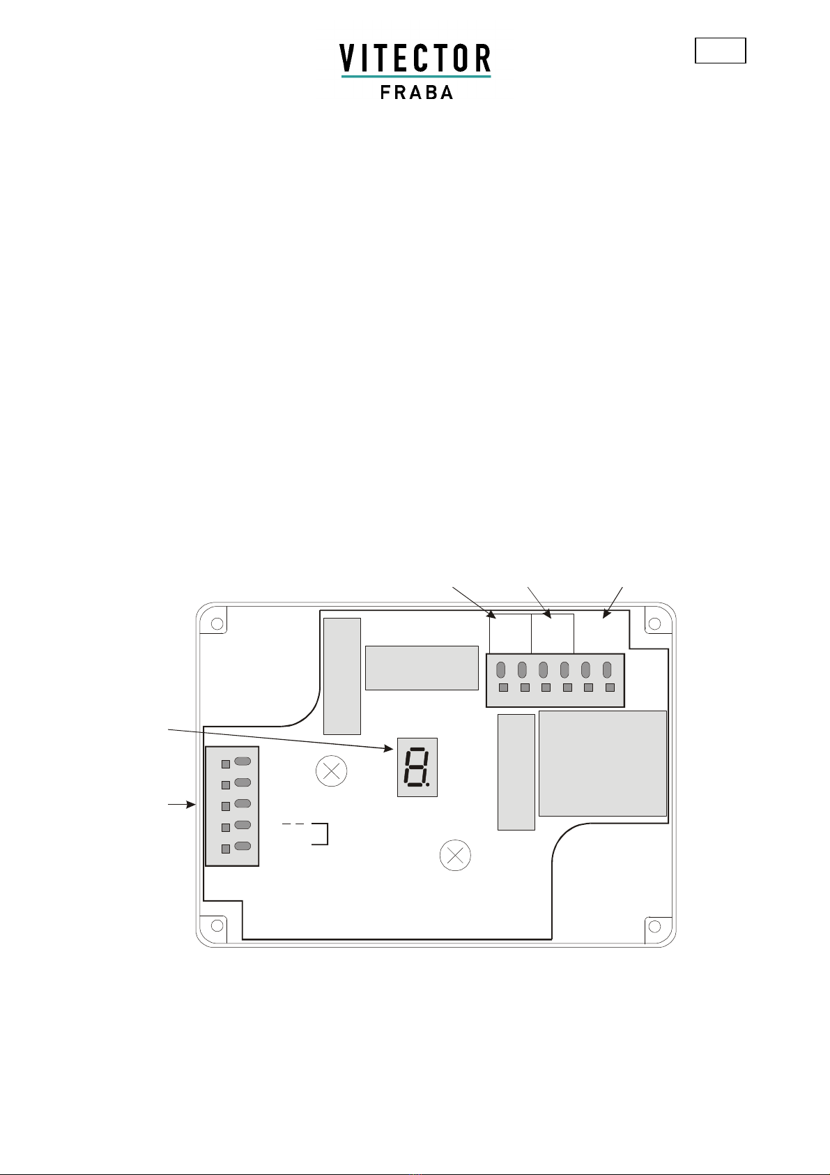
Terminal assignment/wiring for one or two safety devices
Terminal de
signation
Function
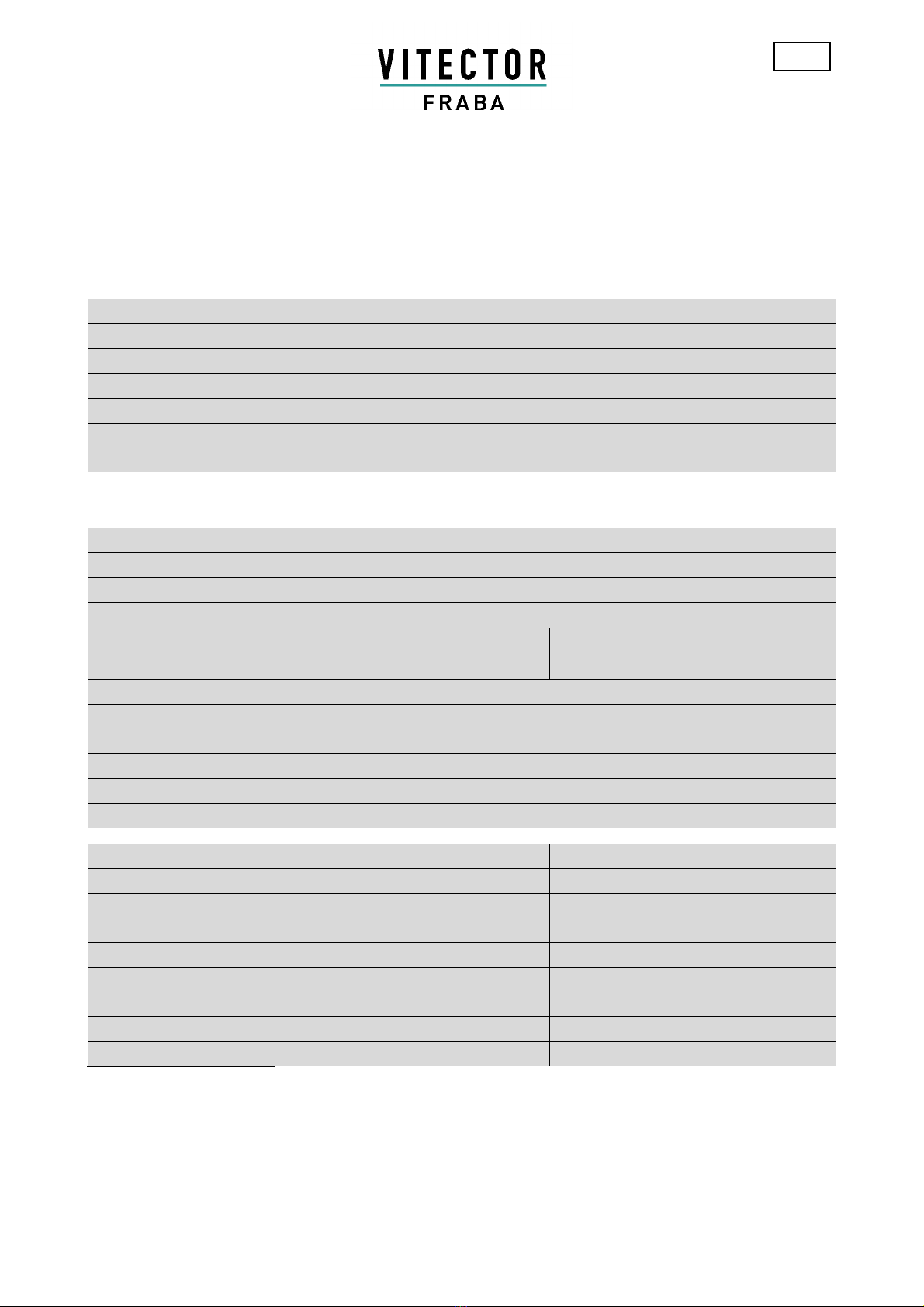
Power A1, A2 Power supply : OSE-C 2300: 230 V AC +/- 10%; protection class II (DIN EN 60529)
OSE-C 2301: 24 V DC +/- 20 %
1 BN 12 V – Power supply for the safety devices (brown lead)
2 WE 0 V – Supply for the safety devices (white lead)
4 GN1 Signal transmission for connection of the first safety device (green lead)
5 In case of connection of one safety device: wire bridge to terminal 6
In case of connection of two safety devices: without wire bridge
6 GN2 In case of connection of one safety device: wire bridge to terminal 5
In case of connection of two safety devices: Signal transmission (green) of 2nd safety device
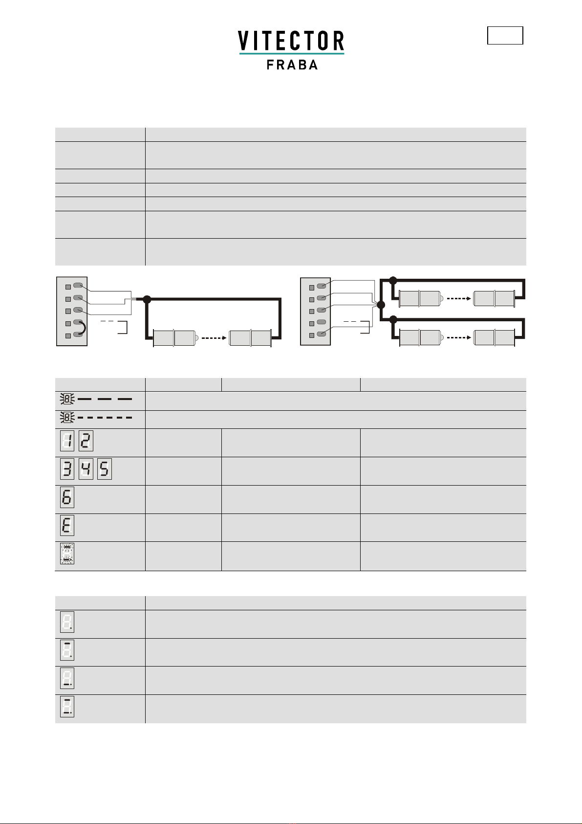
1 BN
2 WE
4 GN1
5
6 GN2
1 BN
2 WE
4 GN1
5
6 GN2
Operating status, fault diagnosis, trouble-shooting (displayed 5 s after power on)
LED display
Operating status
Possible cause
Remedy
Status of safety device 1 connected at terminal 4 is displayed by a slow flashing display
Status of safety device 2 connected at terminal 6 is displayed by a fast flashing display
safety device
OK
low transmission power not necessary
safety device
sufficient
medium transmission power not necessary
safety device
bad
maximum transmission power;
maybe rubber profile bad
check assembly and quality of the rubber
profile
safety device
defect
defect;
sensor, cable, permanent actuation
check, maybe change: cabling, sensors,
rubber profil
segments
flashing
failure rapid shut-down,
maybe the control unit is defect
turn off and on again, maybe change contol
unit OSE-C 2300 / 2301
Indications (at continous operation)
LED display
Operating status
decimal
point
Ready for working
upper
segment
safety device 1 at terminal 4 in function and enabled
lower
segment
safety device 2 at terminal 6 in function and enabled
both
segments
By usage of one safety device at terminal 4 both segments are displaying the function of this safety device
(wire bridge from terminal 5 to 6!).

M A N U A L O S E - C 2 3 0 0 / 2 3 0 1 V 3 . 0
Revision: 2016-07-13 Fraba GmbH 7 / 8
Zeppelinstr. 2, D - 50667 Köln
Tel.: +49 (0) 221 - 9 62 13-0, Telefax +49 (0) 221 - 9 62 13-60, www.vitector.de, info@vitector.de
GB
Security advice
Only instructed persons are allowed to open the housing!
High voltage inside!
Safety regulations
-The unit should be installed and operated by persons,
who are familiar with these instructions and the current
regulations for safety at work and accident prevention.
Follow local regulations especially as regards preven-
tative measures. Safety level of machine and safety
equipment depends on reliability of the used interface.
-Avoid mechanical vibrations greater than
5 g/33 Hz both.
-Replacement and use of components, which are not
certified by the producer may cause safety risk. Any
guarantee is void following opening of the housing or
unauthorised modifications.
-Adequate fuse protection must be provided on all
output contacts with capacitive and inductive loads.
-The safety contacts are separated safely regarding to
DIN VDE 0110 part 1 up to 300 V.
Maintenance
The safety edge shall be tested yearly by optical inspec-
tion concerning defects. In case of any defect the safety
edge shall be changed because the safety function is not
guaranteed completely. The following inspections shall be
done:
-Inspection of the rubber profile concerning defects e.g.
cracks
-Inspection of the rubber profile concerning decreased
elasticity e.g. due to aging
-Inspection of a close mounted seat
-Triggering of the safety edge by hand obstructing the
rubber profile

M A N U A L O S E - C 2 3 0 0 / 2 3 0 1 V 3 . 0
Revision: 2016-07-13 Fraba GmbH 8 / 8
Zeppelinstr. 2, D - 50667 Köln
Tel.: +49 (0) 221 - 9 62 13-0, Telefax +49 (0) 221 - 9 62 13-60, www.vitector.de, info@vitector.de
GB
Safety Properties
The safety properties are valid for the safety edge connected at contact 33/34 ("OSE"). The contact 23/24 ("Rev") does
not contain any safety category. The safety properties are valid for the combination of
OSE-C 2300/2301, OSE-T 1100, OSE-R 1100 and OSE-C 2300/2301, OSE-T 6521, OSE-R 6501. They do not include
values of the rubber profile.
Category 3 (EN 13849-1:2008)
Performance level c (EN 13849-1:2008)
Maximum usage duration 20 years
MTTFd *) 44 years
PFH *) 1,8 x 10
-
7
per hour
DC 63 %
Reaction time 16 ms
*) valid for B
10d
= 1,8 x 10
5
and N
op
≤4 per hour
General Technical Data
Protection class IP 65 (DIN VDE 0470)
Housing material PC, grey RAL 7035, transparent cover
Dimensions LWH: 94 x 130 x 60 mm (without wire fittings)
Operating temperature -20 °C to +55 °C
Supply voltage OSE-C 2300:
OSE-C 2301:
230 V AC ±10 %, 48 Hz – 64 Hz
24 V DC ±20 %
Power consumption max. 2,8 VA
External fuse for power
supply
not required
Overvoltage category III/4 kV according to DIN VDE 0110, part 1
Pollution degree 2 according to DIN VDE 0110, part 1
Weight 0,36 kg
Rela
y Data
Output
33/34 ("OSE")
Output
23/24 ("Rev")
Contact material Hard silver, AgNi Hard silver, AgNi
Switching voltage max. 250 V AC/DC 250 V AC / 24 V DC
Max. current load 4 A 6 A
Switching current max. 4 A 6 A
Max. switching capacity 1000 VA AC15: 230 V / 2 A
DC13: 24 V / 3 A
Mechanical service life 20 x 10
6
operating cycle 20 x 10
6
operating cycle
Fusing 4 A slow blowing (not part of unit) 6 A träge (not part of unit)
This manual suits for next models
1
Table of contents
Languages:
Other Fraba Control Unit manuals
Popular Control Unit manuals by other brands

DAS SOLAR
DAS SOLAR WH108PA user manual

PA
PA VB 200 quick start guide

Hamamatsu Photonics
Hamamatsu Photonics C10507 Series instruction manual

Arbor Technology
Arbor Technology EmETXe-i2309 Quick installation guide

Vaillant
Vaillant auroMATIC VRS 560 OPERATING AND INSTALLATION Manual

Samson
Samson 3323 Mounting and operating instructions