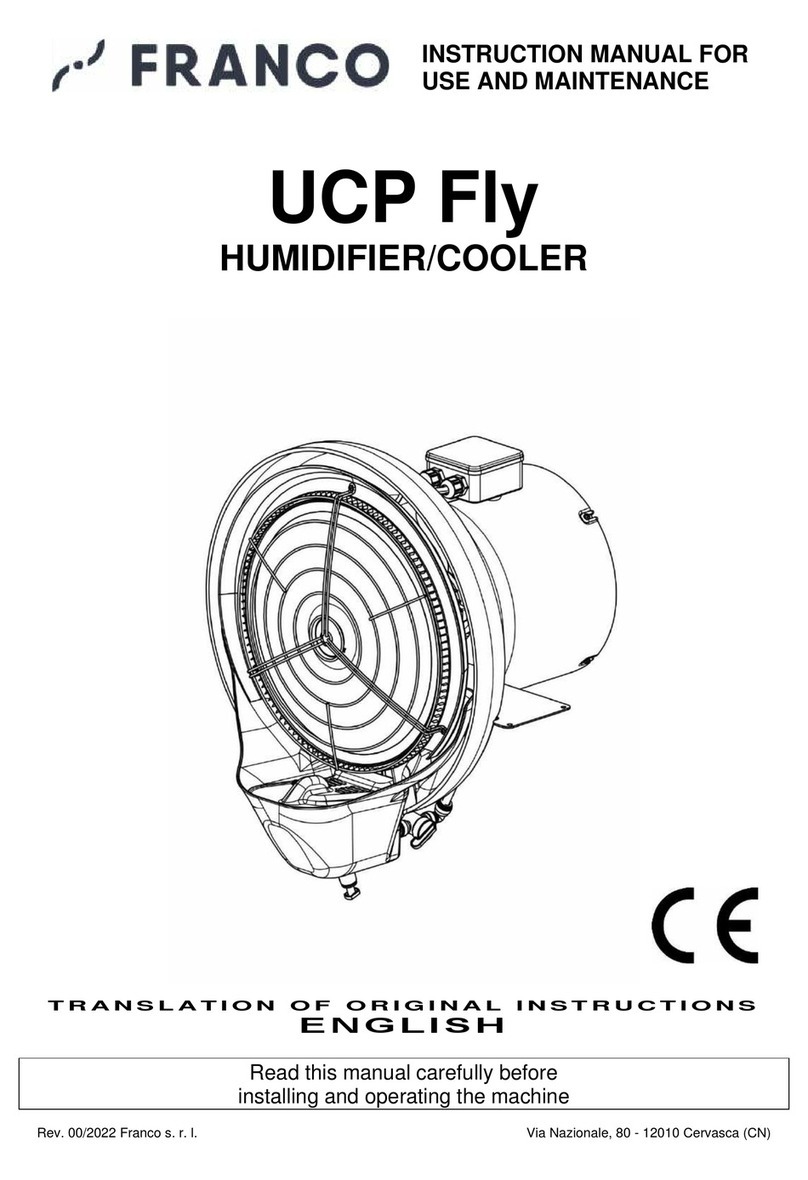
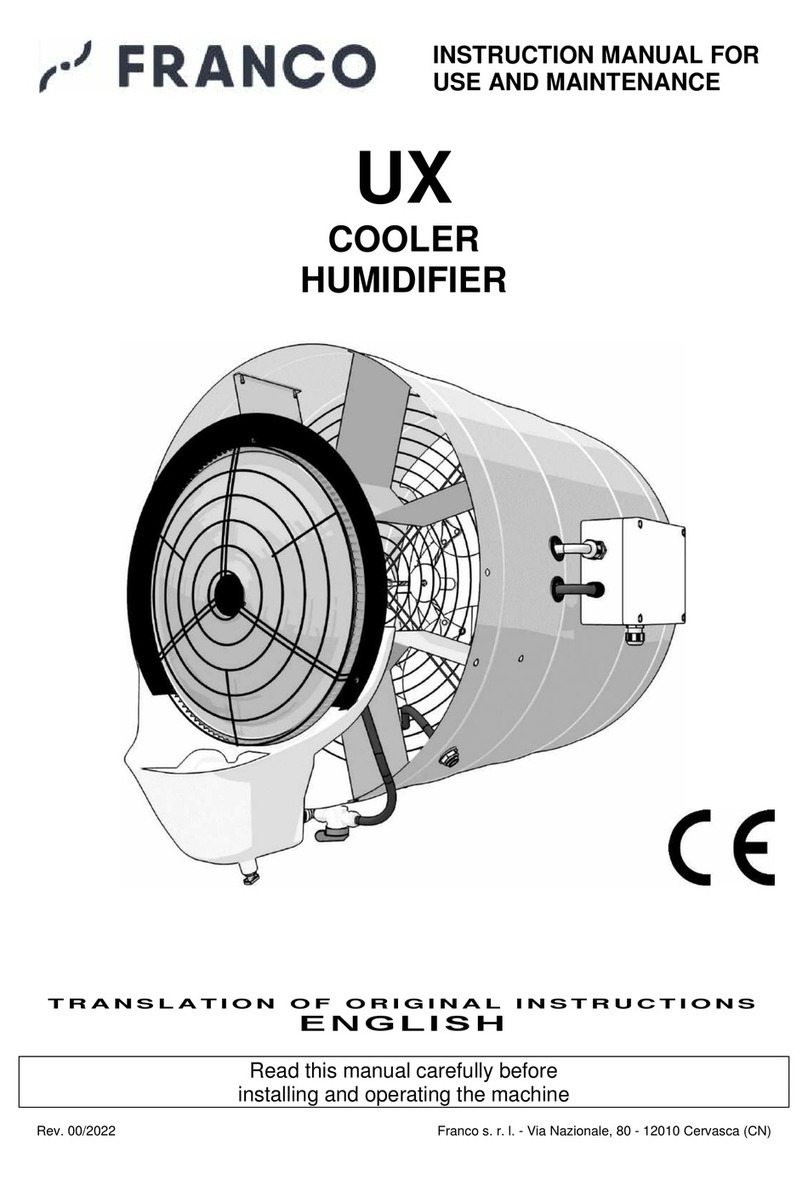
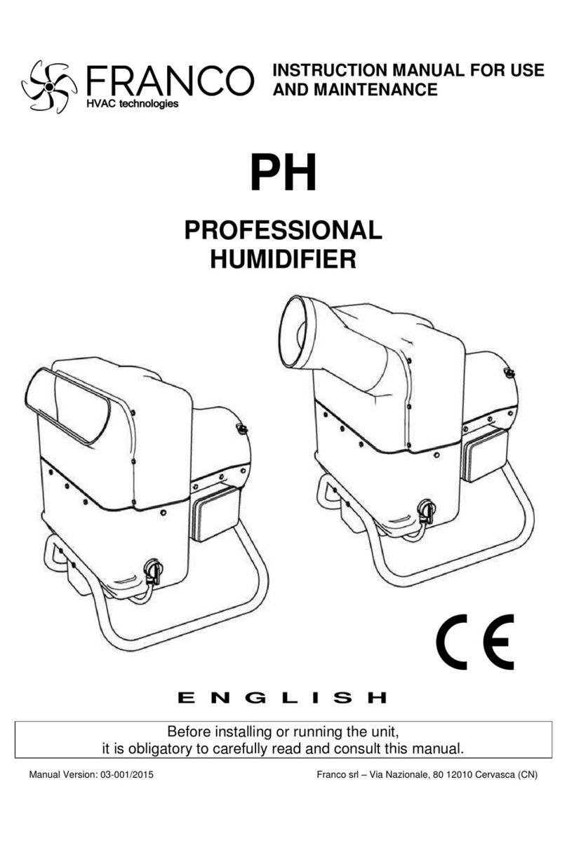
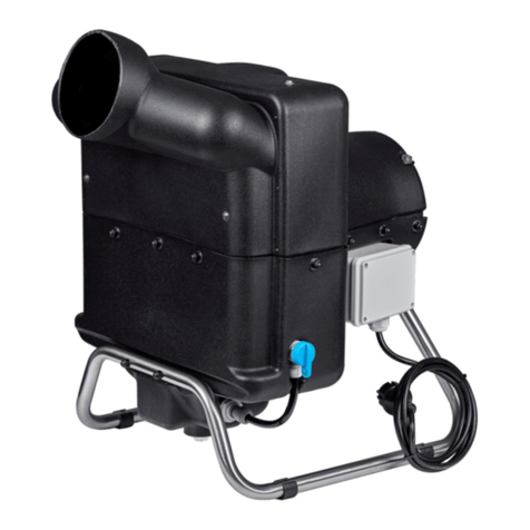
FRANCO UCP-1 User manual

INSTRUCTION MANUAL
FOR USE AND MAINTENANCE
UCP
CENTRIFUGAL HUMIDIFIER
TRANSLATION OF ORIGINAL INSTRUCTIONS
ENGLISH
Read this manual carefully before
installing and using the machine
Rev. 00/2021 Franco s.r.l. - Via Nazionale, 80 - 12010 Cervasca (CN)

UCP Instruction Manual
2
INDEX
1 - INTRODUZIONE 3
1.1 General safety warnings 3
1.2 Guidelines for the correct disposal of the product 3
1.3 Conventions used in this manual 3
1.4 Storage and update of the instruction manual 4
1.5 Target readers 4
1.6 Pictograms 5
1.7 Applications 7
1.8 Versions 7
1.9 Machine identification and data label 7
1.10 Appliance description 8
1.11 Transport and handling 8
1.12 Warranty 9
1.13 Manufacturer's identification data 9
1.14 Declarations 9
1.15 CE Declaration of Conformity 10
2 - INSTALLATION 11
2.1 Preliminary operations 11
2.2 Positioning 11
2.3 Electrical connections 13
2.4 Hydraulic connections 13
3 - OPERATION 14
3.1 Preliminary operations 14
3.2 First start-up 14
3.3 Start-up 14
3.4 Water flow adjustment 14
4 - MAINTENANCE 15
4.1 Cleaning the disc 15
4.2 Cleaning the water tank 15
4.3 Replacing and cleaning the pump 16
4.4 Replacing the rotating disc 16
4.5 Replacing the float 18
4.6 Replacing the nozzle 18
4.7 Accessories 18
5 - TECHNICAL SPECIFICATIONS 19
5.1 Technical Data 19
5.2 Wiring diagrams 20
6 –TROUBLESHOOTING GUIDE 21
7 - SPARE PART LIST 22

UCP Instruction Manual
3
1 - INTRODUCTION
1.1 General safety warnings
This appliance must be used only for the function for which it has been designed: "Adiabatic humidifier /
cooler". Any other use is to be considered improper and dangerous. Franco s.r.l. cannot be held responsible
for any damageresultingfrom improper, incorrect and unreasonableuse or if the appliance is used insystems
that do not comply with current safety standards.
- As you open the package, check that the machine is undamaged, especially paying attention to damages
or deformations of the plastic parts that may lead to breakage and/or malfunction during
use. In such cases, do not connect the machine to the power supply. Periodically carry out a general check
of the machine.
- Before connecting the appliance, make sure that the data on the data label correspond to those of your
electrical network. The data label (see par. 1.9) is located on the back of the unit.
- Observe the safety rules in force for electrical equipment and namely:
•Follow the installation instructions of the appliance
•Do not place objects on the humidifier
•Prevent children and/or incapacitated persons from using the device without proper supervision
•Do not touch the humidifier during operation or while the disc is stopping
•Never immerse the device in water or any other liquid
•Do not put any objects inside the tank as this could cause irreparable damages to the unit
•Do not use accessories, spare parts or components not specified or supplied by the manufacturer
•Avoid touching the unit with wet or damp hands
•Do not pull the power cords or expose them to a risk of shearing
•Do not leave the unit exposed to the weather (rain, sun, etc.).
•In case of failure or malfunction of the appliance, turn it off immediately and disconnect the power
supply. Do not attempt to open or tamper with the appliance: contact a qualified technician.
•Do not attempt to fill or empty the tank while the unit is in operation.
1.2 Guidelines for the correct disposal of the product
Pursuant to European Directive 2012/19/EU:
At the end of its service life, this product shall not be disposed of with urban waste.
It can be delivered to the special separate waste collection points set up by local
authorities, or to retailers who provide this service. Disposing of the product separately
avoids possible negative consequences for the environment and for health deriving from
its inappropriatedisposal and allows the recoveryof the materials of which it is composed,
in order to obtain an important saving of energy and resources. To emphasize the
obligation to dispose of electrical and electronic equipment separately, the product bears
the crossed-out wheeled bin mark.
1.3 Conventions used in this manual
The manual is divided into chapters, in which, where necessary, the type of operator to whom the instructions
are addressed is specified.
The sequence of chapters follows the life stages of the machine.
To make the text easier to understand, terms, abbreviations and pictograms are used, with the following
meaning:
UCP Instruction Manual
4
ABBREVIATIONS
Ch. = Chapter
Par. = Paragraph
Pag. = Page
Fig. = Figure
Tab. = Table
UNITS
The units of measurement used are those of the International System (SI).
1.4 Storage and update of the instruction manual
The instruction manual must be kept with care and must accompany the machine in all transfers of ownership
that it may have during its life. Parts must not be removed, torn or arbitrarily modified.The manual should be
stored in an environment protected from humidity and heat and in proximity of the machine to which it refers.
Upon request, the Manufacturer can provide additional copies of the instruction manual. You can request it
by writing to support@francosrl.com.
The Manufacturer reserves the right to modify the design and make improvements to the machine without
informing the Customers, and without updating the Manual already delivered to the user. However, in the
event of changes to the machine installed at the Customer's premises, agreed with the Manufacturer and
involving the modification of one or more chapters of the Instruction Manual, it will be the Manufacturer's
responsibility to send the users involved the chapters affected by the change. It is the responsibility of the
User to replace the old chapters, home page and table of contents with the new ones in all copies owned.
The Manufacturer is responsible for the original version in Italian language; in case of doubts about the
translated versions, please refer to the Italian language and contact the Manufacturer
(support@francosrl.com) for the due checks.
1.5 Target readers
This manual is intended for the Installer, the Operator and the Qualified Personnel authorised to operate
the machine.
OPERATOR: means the person(s) in charge of installing, operating, adjusting, cleaning, repairing and
moving a machine and performing the simplest maintenance operations;
QUALIFIED PERSONNEL / QUALIFIED WORKER: means those persons who have followed specialisation
courses, training, etc. and have experience in the installation, commissioning and maintenance, repair,
transport of the machine.
The machine is intended for industrial use, and therefore a professional and not a general use, so its use
must be entrusted to qualified persons, in particular who:
•Have reached the age of majority;
•Are physically and mentally able to carry out technically difficult works;
•Have been adequately trained in the use and maintenance of the machine;
•Have been judged by the employer to be suitable for the task assigned to them;
•Are able to understand and interpret the operator's manual and safety instructions;
•Know the emergency procedures and their implementation;
•Have the ability to operate the specific type of equipment;
•Are familiar with the relevant regulations;
•Have understood the operating procedures defined by the machine manufacturer.

UCP Instruction Manual
5
The equipment may be used by persons with reduced physical, sensory or mental capabilities, or lack of
experience or knowledge, provided they are supervised or have received instructions concerning the safe
use of the equipment and an understanding of the related hazards.
1.6 Pictograms
This section explains the meaning of the pictograms that describe the operator's qualification, the hazards
and the obligations/prohibitions to be respected. Pictograms allow to provide rapid and unambiguous
information necessary for the correct use of the machine in safe conditions.
PICTOGRAMS RELATED TO THE OPERATOR’S QUALIFICATION
Symbol
Description
General labourer:operator without specific skills, able to carry out only simple tasks
following the instructions by qualified technicians.
Driver of lifting and handling equipment: an operator qualified to use lifting and handling
equipment and machines (strictly in accordance with the manufacturer's instructions), in
accordance with the laws in force in the Country of destination of the machine.
Mechanical maintenance technician: a qualified technician, able to operate the machine
under normal conditions, to run it with jogging inching operation (JOG) with guards off, to
work on the mechanical parts to carry out the necessary adjustments, maintenance and
repairs. Typically, he is not qualified to work on live electrical installations.
Electrical maintenance technician: qualified technician, able to operate the machine
under normal conditions, to operate it with jogging inching operation (JOG) with protections
disabled, is in charge of all electrical interventions of adjustment, maintenance and repair.
He is able to operate inside live cabinets and junction boxes.
Manufacturer's technician: a qualified technician made available by the manufacturer to
carry out operations of a complex nature in particular situations or, in general, as agreed
with the end user. The skills are, depending on the case, mechanical and/or electrical and/or
electronic and/or software.

UCP Instruction Manual
6
SAFETY RELATED PICTOGRAMS (ISO 7010)
Pictograms contained in a triangle indicate DANGER.
Pictograms contained within a circle impose a PROHIBITION/OBLIGATION
Pictogram
Description
Dangerous electrical voltage.
General hazard.
Do not remove safety guards and devices.
Do not clean, oil, grease, repair or adjust moving
parts by hand.
Cut power before starting work or repairs.
Protective gloves are mandatory.
Mandatory safety footwear.
Helmet is mandatory.

UCP Instruction Manual
7
1.7 Applications
In industry, the UCP is installed inside air handling units or in front of a fan, with air speed > 3 m/s, in rooms
where it is necessary to maintain a certain level of humidity, for example in cold storage rooms for fruit and
vegetable preservation, in seasoning warehouses, in the paper and tobacco industries and in textile
companies.
In agriculture it is used to humidify mushroom farms and greenhouses, and for pest control treatments.
In zootechnics it is used to cool breeding premises and in plants to spray disinfectants or other chemical
products into the environment.
Other than as a humidifier, the device can also be used as an adiabatic cooler. A cooling effect is made
possible because the atomized water in contact with the ambient air tends to evaporate, subtracting heat and
lowering the temperature. The cooling capacity depends on many variables, such as temperature, ambient
humidity and air distribution.The water mains pressure should be 2 - 4 atm (0.2 - 0.4 MPa).
This machine should only be used for the purpose
for which it was designed:
HUMIDIFICATION / ADIABATIC COOLING
All other uses are considered improper and potentially dangerous.
1.8 Versions
The UCP centrifugal dehumidifer is available in the following versions:
1809001 UCP-1 230V ~50Hz single-phase
1809003 UCP-3 400V3 ~ 50Hz three-phase + neutral
1.9 Machine identification and data label
Each machine is identified by a CE data label on which the article number, the serial number and the technical
data are indelibly printed (Fig. 1.9.1).
Always quote these references when contacting the manufacturer or his service dealers.
Fig.1.9.1 CE Data label

UCP Instruction Manual
8
1.10 Appliance description
Components of the centrifugal humidifier (Fig. 1.10.1)
Fig.1.10.1
1.11 Transport and handling
The machine is packed in robust carton boxes.
Be very careful when opening the package to prevent damaging the components. Check the integrity of the
unit by checking that there are no visibly damaged parts. Do not disperse the packaging elements in the
environment: they must be placed in appropriate collection areas.
The UCP can be raised and suspended using the motor base as a support.
Rotating disc
Disc cap
Tank cover
Rear cover
Float valve
Water pump
Nozzle
Motor
Water inlet ½”
Regulating valve
Drain hole with quick connection ⅜”
and cap
Fixed disc
Protection grid
(accessory)
Water collection tank

UCP Instruction Manual
9
WARNING! Before moving:
a. stop the machine;
b. cut off the power supply;
c. cut off the water supply.
Use suitable lifting gear to lift the machine. The weight is indicated on the data label and in the technical
data table (see Par. 5.1). Lift the machine carefully, positioning the lifting belts appropriately.
1.12 Warranty
This appliance is guaranteed for 12 months from the date of manufacture for all faults attributable to a proven
manufacturing or material defect. The warranty does not cover all parts damaged by transport, bad or
incorrect maintenance, neglect, inability to use, improper use, tampering by unauthorised personnel and in
any case by causes beyond the control of Franco s.r.l. Cervasca (CN). During the warranty period, Franco
s.r.l. undertakes to supply free of charge those parts that may be defective at the origin. Any technical repair
must be carried out by an authorized and qualified technician.
1.13 Manufacturer's identification data
Manufacturer
FRANCO s.r.l.
Legal and administrative seat
VIA NAZIONALE, 80 - 12010 CERVASCA (CN) - ITALY
Contacts
Tel.: (0039) 0171 - 61.16.63
Email: support@francosrl.com
Web: francosrl.com
1.14 Declarations
The machine to which this manual refers is manufactured in compliance with the relevant European
Community legislation applicable at the time of its placing on the market.
The machine is not included among those mentioned in the Annex IV of Directive 2006/42/EC.

UCP Instruction Manual
10
1.15 CE Conformity Declaration
THE MANUFACTURER
FRANCO s.r.l.
Company
Via Nazionale, 80 12010 CN
Address Postal code Province
Cervasca Italy
City Country
DECLARES under his own responsibility that the machine
Humidifier / Cooler UCP-1 / UCP-3
Description Model
1809001 / 1809003
Item number
UCP Centrifugal Humidifier
Trade name
Humidification/Cooling in combination with dynamic ventilation system (air velocity > 3 m/s)
Intended use
complies with the following European Directives:
2006/42/CE Machinery Directive
(2014/35/UE) (Low Voltage Directive)
2014/30/EU Electromagnetic Compatibility Directive
Harmonized standards and reference specifications used:
EN 12100:2010
EN 60335-1:2012 + A11 +A13 +A1 + A14 + A2 +A15:2021
EN 60335-2-98:2003/A11:2019
EN 60335-2-41:2003/A2:2010
EN 60034-1:2010
EN 55014-1 :2017, EN 55014-2:2015, EN 61000-6-1:2016, EN 61000-6-3:2010
Legal entity authorized to compile the Technical File:
FRANCO s.r.l.
Name
Via Nazionale, 80 12010 CN
Address Postal code Province
Cervasca Italy
City Country
Place and date
The Manufacturer
Cervasca, 20/10/2021
Signature
Rev. 00/2021
Marco Fantino
Administrator

UCP Instruction Manual
11
2 - INSTALLATION
2.1 Preliminary operations
To make the UCP humidifier operational, you need:
•Electrical system with voltage and frequency suitable for the machine, with grounding and
protection devices;
•Water supply connection: required pressure 2-4 atm (0.2-0.4 MPa);
•Ambient temperature during operation: must be between 1°C and 40°C
•Temperature of water and liquids used: must not exceed 35°C.
•Drinking water with low fixed residue, or treated. The quality of the water affects the frequency of
maintenance operations and the correct functioning of the humidifier.
•Dynamic ventilation system (air speed > 3 m/s);
•It is suggested to provide a timed control for the tank drainage with bleed-off function, to keep the
machine in optimal working conditions.
The installation must comply with the applicable European, national and local standards in
force. In particular, follow the requirements of standard UNI 8884 "Characteristics and
treatment of water in cooling and humidification circuits" where conductivity is less than 100
S/cm and total hardness less than 5° fH (50 ppm CaCO3) or other equivalent national standards.
.
2.2 Positioning
To enable optimum humidification, the UCP unit should be installed in front of an air circulator or
integrated into a forced ventilation system.
It must be installed in a horizontal position, with the water collection tank at the bottom, raised off
the ground.
Use the holes on the motor feet to fasten the machine: the hole distances are shown in figure 2.2.1. The
fixing must be stable.
YES
NO
Fig. 2.2.1 - Hole distances for fastening
The UCP must be positioned respecting the minimum recommended distances that allow to operate the
machine properly and to carry out the required maintenance (see Fig. 2.2.2).
If the humidifier is used in combination with a fan, to avoid mist condensation on the walls, maintain a distance
of at least 1 m from ceiling and side walls. The distance from the wall in front of the machine should be
calculated according to the air throw of the ventilation system used. Choose the most suitable position for
room humidification or cooling, according to the type of installation chosen.
In case of installation inside air handling units or air distribution ducts, since the mist produced tends to
condense on the internal surfaces of the ducts, it is necessary to arrange a system for the discharge of the
condensation water and of the non-atomised water from the appliance. It is also recommended, in order to
improve the quality of the mist released intothe air, to provide a droplet separator downstream the humidifier.

UCP Instruction Manual
12
The UCP humidifier is equipped with a high speed rotating disc. Depending on the type of
installation, different types of protection guards are required (Fig. 2.2.2):
•installation inside ducts or air handling units not accessible from outside: no protection
guard required.
•installation in a room at a height > 2.5 m from the floor: mount the wide pitch protection grid (30
mm),part no. 1801031 available as an accessory. Fix the grille to the body of the appliance using 3
screws 4.2x9.5 part no. 6002004.
•installation in a room at a height < 2.5 m from the floor: fit the fine pitch protection grid (10 mm) part
no. 1801030 available as an accessory. Fix the grid to the body of the appliance using 3 screws
4.2x9.5 part no. 6002004.
Fig. 2.2.2 - Protection guards and safety distances
N.B. : In any case the safety distances from moving parts prescribed by the UNI EN ISO 13857:2008
standard must be respected. Do not remove the protection guards.
Fig. 2.2.3 –Fixing accessories
Bracket for fixing on
ducted fan
Bracket for fixing
on circulator fan
H > 2,5m
H < 2,5m
Minimum distance from walls
and ceiling: 1 m

UCP Instruction Manual
13
2.3 Electrical connections
•The electrical connection must be carried out by recognised and authorised
technicians in accordance with current regulations.
•Make sure that the characteristics of the electrical power supply comply with
those indicated on the data label of the appliance.
•It is mandatory to connect the equipment to an efficient grounding line.
The appliance is supplied with motor and pump power cables, which must be connected to the electrical
mains, referring to the wiring diagrams in Chapter5.2. The use of a humidistat or thermostat is recommended
to control the automatic start and stop of the machine depending on the humidity or ambient temperature;
alternatively, an ON/OFF switch can be used to manually start and stop the machine.
Dans tous les cas, un dispositif permettant de déconnecter l'appareil du réseau électrique doit être prévu. En
outre, un fusible de protection de taille appropriée du type retardé pour le démarrage du moteur doit
également être installé.
2.4 Hydraulic connections
Effectuer le raccordement aux conduites d'alimentation et d'évacuation de l'eau aux points
prévus à cet effet.
(Fig. 2.4.1) :
•Water inlet connection 1/2" M for a hose with threaded connection
•Quick-connect drainage duct with cap for connection of a Ø 3/8" hose
•A specific accessory (Fig. 2.4.1) is available for the quick connection or through a hose connector to
the above mentioned fitting.
N.B.: In order to prevent the float valve assembly from accidentally rotating while the supply pipe is
connected (or disconnected), hold the external fixing nut in place using a hexagonal wrench or other
suitable tool (Fig. 2.4.1).
Fig. 2.4.1 Fig. 2.4.2
To arrange for periodic bleed-off of water from the tank:
a) remove the drain plug by pushing up the stop ring. The operation can be made easier using a hex 10
wrench.
b) connect a flexible pipe to the drain duct, directly or by means of a hose connection (see Fig. 2.4.2)
providing an appropriate cut-off device (e.g. tap, timed solenoid valve, etc.) which must be normally
closed during operation.
Hose holder
fitting*
Quick
connection
fitting*
Fitting for
threaded pipe
½”
*Optional
accessories
Hose holder
fitting*
Quick connection
fitting 3/8”

UCP Instruction Manual
14
3 - OPERATION
3.1 Preliminary operations
Before operating the humidifier, check that:
•All connections, both electrical and hydraulic, have been made according to the instructions contained
in this manual;
•The humidifier is free and clean;
•The water supply tap is open;
3.2 First start-up
•Check that the air flow direction is correct (Fig. 3.2.1);
•On the three-phase model, check the direction of rotation of the centrifugal disc (Fig. 3.2.1);
•Make sure that all cables are properly positioned and that they are not pinched or pulled too tight;
•Make sure that all hydraulic connections have been made correctly;
•Open the water supply tap and check that there are no leaks along the circuit;
Fig. 3.2.1 - First start-up checks
Adjust the water flow rate on the flow regulator until no droplets are dragged from the rotating
disc.
N. B. Excessive water flow will result in increased droplet size.
The pump must never run without water
The temperature of the liquids used must not exceed 35°C.
3.3 Start-up
As soon as the machine is powered up, the motor and pump will start.
The pump willcirculate the water to therotating disc, which will spray the water, and themachine will continue
to operate as long as the power is on. If the machine stops during operation, refer to Chap. 6
"Troubleshooting".
3.4 Water flow adjustment
The quantity of atomised water can be adjusted by acting on the valve that regulates the flow of water to the
rotating disc (see Fig. 3.2.1). The machine can atomize up to a maximum of 40 l/h of water. The quantity of
water affects the mist quality.
Air flow
Correct
rotation
WARNING!
HIGH SPEED
ROTATING DISC
Min. air velocity:
3 m/s
OPEN
CLOSED

UCP Instruction Manual
15
4 - MAINTENANCE
The operations described in this chapter must only be carried out by authorised and qualified
personnel, using suitable personal protective equipment.
Before carrying out any work on the appliance, disconnect it from the mains
and from the water supply.
Periodically check that the quantity of water arriving at the centrifugal disc is correct. If necessary, adjust the
flow regulator. Keep discs, tank and internal components clean to prevent dirt from accumulating on the rear
cover.
4.1 Cleaning the disc
•Keep the disc clean to prevent scale or dirt buildup that could cause increased vibration or coarse
atomization.
•To clean the rotating disc, use a soft damp cloth and a non-toxic, solvent-free detergent, wiping
without pressing too hard.
•Do not use solvents.
•The fixed disc should be cleaned using a brush with stiff bristles. Rub the disc teeth carefully not to
damage them. Any scaling deposit can be removed with vinegar, lemon or another specific non-toxic
chemical that does not contain solvents.
4.2 Cleaning the tank
WARNING!
Stagnant water can cause the growth of harmful bacteria and microorganisms. It is therefore
necessary to prevent water stagnation.
As well as for safety reasons, regular water renewal is also necessary to keep the appliance clean
and free from limescale deposits, mould, etc. It is therefore recommended to provide for a periodic
automatic or manual draining of the water collection tank.
If the machine is only used occasionally, empty the water collection tank after each use. Never leave
water in the tank when the machine is not in use.
•Inspect and clean the drip tank periodically.
•To access it, unscrew the two screws on the cover
and pull gently, using the hook provided.
•To facilitate cleaning operations: remove the float
ball and the pump.
•To remove the ball: unscrew the plastic wing nut of
the float arm (see Fig. 4.2.1).
•To remove the pump: Use a hexagonal wrench to
hold down the stop ring in which the pump is
recessed and gently pull the pump out.
•After you have done this, you can clean the inside of
the tub with a cloth or sponge by gently rubbing the
walls. Do not use solvents.
•Periodically check the operation and cleanliness of
the pump and float. Every 2-3 months wash the internal parts of the pump with lukewarm water.
Fig. 4.2.1

UCP Instruction Manual
16
4.3 Replacing and cleaning the pump
To replace the pump, proceed as follows:
•Unscrew the two cover screws using a Phillips screwdriver and remove the cover.
•Unscrew the plastic wing nut from the float arm. Hold down the stop ring in which the pump is
connected with a fixed wrench (hex 13) and gently pull the pump out.
•Remove the pawl from the outlet of the removed pump and snap it onto the new one.
•Repeat the sequence in reverse, taking care to reposition the float so that the water level inside the
tank completely covers the pump.
The pump does not require any particular maintenance. It may be necessary to clean the internal rotating
parts periodically, also depending on the quality of the water used. In this case:
•Disconnect the pump as described above.
•Turn the swivel outlet fitting to the unlocked position and remove it.
•Remove the rotor and impeller and clean them with warm water and a brush. Any limescale deposits
can be removed with vinegar, lemon or specific products. Do not use solvents.
•Reinstall the fitting and reconnect the pump.
4.4 Replacing the rotating disc
•Remove the front protection grille, if used, by unscrewing the 3 fixing screws.
•Remove the central cap of the rotating disc by levering it in the recess witha small slotted screwdriver
(Fig. 4.4.1).
•Using a screwdriver (hex. 7) unscrew the M4x16 fastening screw of the rotating disc to the motor shaft
and its washer (Fig. 4.4.2).
Fig. 4.4.1 Fig. 4.4.2
•Insert the M8x40 screw supplied with the machine into the central hole of the rotating disc (Fig. 4.4.3)
•Use a screwdriver wrench (hex 13) to tighten the screw which will push the disc out effortlessly as it
enters the hole. (Fig. 4.4.4)
Lever in the
recess
Screw M4x16

UCP Instruction Manual
17
Fig. 4.4.3 Fig. 4.4.4
•Once the disc has been removed, unscrew the M8x40 screw from the rotating disc.
•Apply a small amount of grease on the motor shaft and fit the new disc, checking the alignment of
the keys and pressing on the centre, without tapping or forcing excessively. Reposition the washer,
M4 screw and plug. Check that the 4 mm thick spacer (see section 5.3 "Spare parts list" item 5) is
correctly positioned between the fixed and rotating discs.
4.5 Replacing the float
•Disconnect the water supply and remove any junction fittings from the ½" connection on the machine.
•Remove the two cover screws using a Phillips screwdriver and remove the cover.
•Unscrew the plastic ring nut and remove the float body.
•Position the new float and adjust it so that the water level inside the tank completely covers the pump.
•Reassemble the assembly by repeating the sequence in reverse.
4.6 Replacing the nozzle
•After removingthe rotating disc(see Par. 4.4), remove the nozzle by unscrewing thetwo fixing screws.
•Push the grey ring on the elbow connector (see section 5.3 "Spare parts list" item 19) to the rear of
the disc and, while holding it down, pull the nozzle to be replaced.
•Position the new nozzle by repeating the sequence in reverse.
Screw M8x40

UCP Instruction Manual
18
4.7 Accessories
A complete range of accessories that can be combined with your UCP, such as protection grids, electronic
humidity regulators, thermostats, timed systems for draining and cleaning the tank, accessories for electrical
wiring and hydraulic installation, is available on request.
Ask your supplier for the accessories catalogue for more details.
Mounting UCP on ducted circulators
•Assemble the central plate and the two side brackets using four M6x12 bolts (Fig. 4.7.1).
•Fix the UCP on the central plate by means of 4 bolts M6x12 and 4 washers (Fig. 4.7.2) using the holes on
the motor feet.
•Connect the assembly to the circulator grid by means of 4 bolts M6x12 (Fig. 4.7.3).
Fig. 4.7.1 Fig. 4.7.2 Fig. 4.7.3
Mounting UCP on square circulators
•Fix the two end brackets on the sides of the circulator using 2 screws 4,8x19 per bracket.
•Fix the central bracket to the two brackets by means of 4 screws 4,8x19 (Fig. 4.7.4).
•Fix the UCP on the central plate by means of 4 M6x12 bolts and 4 washers using the holes on the motor
feet (Fig. 4.7.5).
Fig. 4.7.4 Fig. 4.7.5

UCP Instruction Manual
19
5 - TECHNICAL SPECIFICATIONS
5.1 Technical data
UCP-1
UCP-3
Atomization capacity
l/h
40
40
Power supply
single-phase
three-phase +
neutral
Degree of protection
IP56 (motor)
IP68 (pump)
IP56 (motor)
IP68 (pump)
Net weight
kg
6
6
Rated voltage / Frequency
V / Hz
230 ~50
400 3~50
Current rating / Power rating
A / W
1,3 / 220
0,5 / 180

UCP Instruction Manual
20
5.2 Wiring diagrams
Make sure that the characteristics of the electrical supply voltage comply with those
indicated in the table.
Use cables with an appropriate section for the rated current (A) of the device (see Par. 5.1
"Technical specifications").
Install a magnetothermal differential circuit breaker in the power supply circuit upstream of
the unit.
For three-phase version only: connect the motor thermal protector to an external power cut-off
circuit via the two terminals on the motor cable marked "4" and "5".
Make sure that:
•all electrical connections have been made according to the instructions
contained in this manual;
•the appliance has been correctly grounded;
•all applicable safety regulations have been complied with;
If the power supply cable is damaged, it must be replaced by the manufacturer or his technical
assistance service or by a person with similar qualifications, in order to prevent any risk.
N.B. : On three-phase models, check the direction of rotation of the disc. If it is opposite to the
direction shown in the figure, invert the connection of two phases (e.g. U1 and V1) to change
the direction of rotation.
Single-phase
version
Motor cable
Pump cable
Neutral - Blue
Phase - Brown
Earth –Yellow/Green
Neutral - Blue
Phase - Brown
Three-phase
version
Correct
rotation
Motor cable
Pump cable
Neutral - Blue
Phase - Brown
(Earth) - Yellow/Green
U1 Phase - Black
V1 Phase - Black
W1 Phase - Black
4Thermal protector - Black
5Thermal protector - Black
This manual suits for next models
3
Table of contents
Other FRANCO Humidifier manuals

FRANCO
FRANCO UCP Series Instruction manual

FRANCO
FRANCO PH5 Instruction manual

FRANCO
FRANCO UCP Fly Series Instruction manual

FRANCO
FRANCO UX Series Instruction manual

FRANCO
FRANCO UX Series Instruction manual

FRANCO
FRANCO PH Instruction manual

FRANCO
FRANCO UCP Instruction manual

FRANCO
FRANCO UF Mobile Instruction manual

FRANCO
FRANCO PH Instruction manual