manuals.online logo
Brands
  1. Home
  2. •
  3. Brands
  4. •
  5. Franke
  6. •
  7. Hob
  8. •
  9. Franke PRI54GAVTC Release Note

Franke PRI54GAVTC Release Note

1
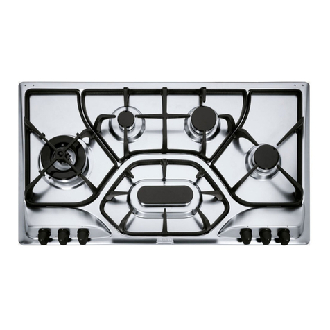
TECHNICAL HANDBOOK HOB PRI5 4GAVTC XS C UK
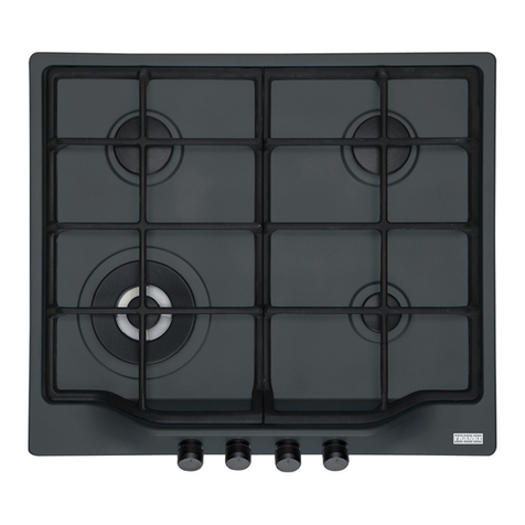
SUKEN 4 /5 BURNER HOOB
PRI54GAVTC SATIN FINISH STAINLESS STEEL 6691615
dimension 970x530 cut out 930x490
Table of contents
User's instructions . . . . . . . . . . . . . . . . . . . . . . . . . . . . . . . . . . . . .
Hob cleaning and maintenance . . . . . . . . . . . . . . . . . . . . . . . . . . .
Technical data . . . . . . . . . . . . . . . . . . . . . . . . . . . . . . . . . . . . . . . . .
Installation . . . . . . . . . . . . . . . . . . . . . . . . . . . . . . . . . . . . . . . . . . . .. . .
TO HAVE ACCESS TO THE FUNCTIONAL COMPONENTS . . . .
Exploded view PRI54GAVTC
SPARE PARTS PRI54GAVTC
Exploded view PRI54GAVTC
SPARE PARTS PRI54GAVTC
UPDATED 03.2006
User's instructions
Igniting the burners
In these models the knob controls both ignition and the safety device. Proceed as follows to ignite the burners:
1) Turn the chosen knob.
2
2) Keep the knob strongly pressed in for 3/4 seconds to permit the spark to light the gas that exits from the flametamer and to permit the
thermocouple to heat up.
3) Release the knob after about 3/4 seconds and adjust the flame as desired, rotating the knob anti-clockwise. Repeat points 1 and 2 if the flame
does not remain on.
Symbols
Circle: valve off;
large flame + star: maximum flow rate;
small flame: minimum flow rate.
Using the burners
For greater efficiency and less gas consumption use pots and pans with the right diameters for the burners. Avoid having flames extending out
from underneath the pans (refer to the table).
Table of recommended pans Ø Pan diameter in cm
SMALL from dia. 8 to dia. 14
MEDIUM from dia. 14 to dia. 20
FAST/RAPID from dia. 20 to dia. 28
TRIPLE-RING Above dia. 26
Automatic safety valves
This safety device automatically closes the gas valve if the burner flame accidentally turns off due to drafts, liquids overflowing from pots or
momentary interruptions in the gas supply. The device takes effect approximately 30 seconds after the flame turns off.
Hob cleaning and maintenance
- All parts made of 18/10 stainless steel will remain just like new if they are cleaned with water and then carefully dried.
- To restore their original gloss they should be periodically cleaned using "Franke inox Creme" and "Franke microfibre cloth" available from your
retailer or from a FRANKE Service Center.
- Absolutely never use steel wool or pads, muriatic acid or any other products that can scratch or grind.
- Avoid leaving acid and alkaline substances on the cooktop or objects made of rusted iron.
• Burners or flametamers can be cleaned after removing them from the hob using hot
soapy water and detergent. Then dry them with care. Make sure gas passages are perfectly clean. These components can also be washed in a
dishwasher.
• Pan grillplates in the pan support section change in colour due to the action of heat. To clean them proceed as with the burners or wash them in a
dishwasher.
TYPE OF GAS BURNER INJCTOR MARKING RATED THERMAL REDUCED THERMAL RATED
3
CAPACITY IN
WATTS CAPACITY IN WATTS CONSUMPTION
G20 NATURAL GAS
METHANE 20 MBAR SMALL
MEDIUM
FAST/RAPID
TRIPLE-RING
72
97
115
140
1000
1750
3000
3300
400
440
800
1600
95 L/H
167
286
314
G30-G31
LIQUEFIED GAS
30/37 MBAR
SMALL
MEDIUM
FAST/RAPID
TRIPLE-RING
50
65
85
91
1000
1750
3000
3300
400
440
800
1600
73 G/H
127
218
240
Supply voltage: 220/230 V 50 Hz
Overall thermal capacity: see the identification plate on the bottom of the cooktop.
Combustion supporting air: 2 m3/h per kW of installed power - see identification plate.
Installation
Installation and connection to the mains should be carried out in compliance with national laws in force.
The following paragraphs describe installation procedures both for the gas and for the electrical sections. These tasks must be performed
according to current standards and by qualified personnel: performance by inexpert persons can create dangers. The manufacturer
declines all responsibility for harm to persons or property caused by failure to comply with these requirements.
Important
- The appliance must be installed by expert and qualified personnel according to
current standards.
- Turn to a Franke Service Centre for all repairs and maintenance.
- Never use deformed or unstable pots and pans on the burners which could overflow
or tip over.
- If the appliance has a cover make sure the burners are cool before closing the cover.
- Close the gas supply valve when the hob is not being used.
Franke S.p.A. declines all responsibility for harm to persons or property caused by
failure to comply with standards. This appliance can only be used for cooking.
Any tampering with or modification to the appliance can be a source of danger. Make
sure gas distribution systems are as required before installing the appliance. The gas
for which the hob is designed is indicated on the label on the bottom of the control
box. This appliance
4
is not joined to a device for evacuating products of combustion and must be installed and hooked-up according to current regulations.
Special attention must be given to ventilation. The appliance may have hot parts during operation: keep children and the handicapped distant. Use
of gas-fired cooking appliances generates heat and humidity in the room where they are installed. Make sure the room is properly ventilated.
Keep natural ventilation openings free and open or install a mechanical ventilation device (extraction hoods with exhaust ducts). Intense and
prolonged use of the appliance may require supplementary ventilation such as opening a window or taking measures for more efficient ventilation
by, for example, increasing fan powers. Preparing the cabinet
IMPORTANT: The Franke low-profile hob requires a worktop with a thickness of at
least 40 mm.
If the worktop is lower than 40 mm, for a correct installation put special shims near the
hooks.
INSTALLING model PRI 5 4GAV-TC (970x530 mm)
Prepare the cut-out in the worktop with the following
dimensions:
When installing the model PRI 5 4GAV-TC hob on a 900 mm base the hob can be
centered on the base (see fig. 2).
Prepare the cut-out in the worktop with the following dimensions: fig. 2
INSTALLING model PRI 4 4GAV (970x530 mm) 14
The PRI 4 4GAV model can be positioned in the center of the base (see fig. 3) when
the base is 600 wide. fig. 3
Otherwise, the hob can be positioned by centering the cooking area (see fig. 4) with
respect to the base. fig. 4
Important
These are "Y" appliances in terms of fire protection. They can be installed built-in even near wooden walls higher than the worktop in which they
are installed as long as there is a minimum distance from the edge of the appliance equal to: 50 mm. for the side wall, 30 mm. for the rear wall and
at least 700 mm from wall cabinets hung over the hob.
Connection to the gas pipeline
There are two ways of making the connection to the gas pipeline:
A) Connect the gas hob using a dia. 12 mm rigid copper tube as illustrated in figure 5. To
guarantee a proper seal insert the elastomer seal provided with the appliance.
B) Connect the hob using a solid wall flexible steel tube. Here, too, you must insert the seal that is
furnished in order to ensure a proper seal. We also recommend compliance with standards
regarding gas-fired appliances.
5
Check for leaks after making the gas connection
Room ventilation
Make sure there are permanent openings to the outdoors in the room where the appliance is installed or vent ducts that permit a proper flow of air.
All openings that are made must:
1) have a minimum 100 cm2 cross-section area;
2) be designed so that they cannot be blocked from the outside or the inside;
3) be pro tected so that their ventilation passage is not reduced in size;
4) be high enough above floor level to prevent interference with combustion exhaust.
When openings are made in the wall of an adjacent room this room must be directly vented and, in addition, must not be:
1) a bedroom
2) a public room in the building
3) a room where there is a fire hazard
Before testing the appliance check that the room where the vent opening is made is not in depression due to operation of another appliance and
that ventilation between the two rooms is guaranteed by permanent and unimpeded openings such as increased gaps between door and floor.
Products of combustion must be exhausted by a hood which must, in its turn, discharge into a stack, chimney or directly to the exterior.
Access to the cooktop
Access to these operating components is from below after removing any other appliance installed underneath the cooktop (for example, ovens,
dishwashers, etc.). This makes it possible to remove the casing from below. These appliances can be installed above a 60 or 90 cm. oven.
NOTE: All products supplied from the factory are set up
for methane gas.
Proceed as follows to change injectors when other gases
are used:
1 - remove the grillplates and burners;
2 - remove the injectors by unscrewing them and replace
them with injectors suitable for
the gas being used. Make sure they are marked as
indicated in the table (page 13);
3 - after replacing the injectors check that they are
perfectly sealed using a soap and
REPLACING INJECTORS ADJUSTING MINIMUM
6
water solution (dry them well before putting the burners back in place);
4 - reinstall burners and grillplates;
5 - these burners do not require adjustment of air supply;
6 - replace the set-up label supplied in the package of accessories.In this case there must be a separation partition between appliance and oven.
Warning
Always put the proper adhesive label (supplied as an accessory with the nozzles) in the space on the identification plate when transforming the
appliance from one type of gas to another. When the appliance operates with LPG (G30 or G31) the adjustment screwmust be tightened all the
way in. These appliances are supplied as category II 2H3+
devices.
Adjusting minimum
Remove the knobs and turn on the burners and adjust minimum through the hole in the valve shafts using a screwdriver (supplied with the
appliance). Rotate it anti-clockwise so as to increase the minimum. The burner flame must be stable even if the knob is moved suddenly from
maximum to minimum. fig. 6
Electrical connection
The connection must be made by qualified personnel according to current standards and according to the rules of the trade.
• Make sure grid voltage corresponds to the voltage indicated on the identification plateon the bottom of the hob. Make sure the electrical system,
meter, fuses, switch, plug and outlet are correctly sized for the current absorption rate of the hob.
• Fit a standard plug to the cable and connect it to a suitable power outlet. The yellow/green cable must be used to make the ground connection.
When installation is terminated the outlet must be accessible in order to be able to disconnect the hob from the electric grid when performing
cleaning and maintenance. When the connection is permanent then install a multi-pole switch between the appliance and the electric grid. This
switch must meet current regulations and have a minimum 3 mm gap between contacts.
• The law requires the hob to be connected to an efficient ground system. The cable's ground conductor is coloured yellow/green and must never
be interrupted. Make sure the ground system is efficient before making electrical connections.
• Franke S.p.A. declines all responsibility for any damage to persons or property caused by failure to comply with these standards.
7
TO HAVE ACCESS TO THE FUNCTIONAL COMPONENTS
To have access to the functional components, the part below the hob must be easily accessible: any other domestic appliances (i.e. oven,
dishwasher, etc.) should be therefore removed in advance.
Having done so, it becomes possible to unscrew the hob’s brackets.
Once the brackets have been loosen, move them towards the inside of the hob, remove pan stands, burner caps and burners and lift the hob to
remove it from its place.
After the hob has been removed from the hole in the work-top, unscrew the injector-holders from the hob and remove bezels and knobs
You can now access the hob functional parts.
8
9
PRI54GAVTC
1981100 CONICAL MICRO DRIVE SPRING 1981469 FIXING CONICAL MICRO SPRING
10
PRI54GAVTC 6691615
POS. CODE DESCRIPTION QUANTITY
1 1980773 5 BURNER IGNITION GENERATOR 1
2 1981102 TERMINAL BOARD 1
3 1980042 POWER CABLE 1
4 1981337 MEDIUM BURNER INJECTOR HOLDER 2
5 1981336 AUXILIARY BURNER INJECTOR HOLDER 1
6 1981338 RAPID BURNER INJECTOR HOLDER 1
7 1981562 TRIPLE RING BURNER INJECTOR HOLDER 1
8 1981404 HOSE FOR CONNECTING TO THE AUXILARY BURNER 1
9 1981407 HOSE FOR CONNECTING TO THE TRIPLE RING BURNER 1
10 1981405 HOSE FOR CONNECTING TO THE RAPID BURNER 1
11 1981406 HOSE FOR CONNECTING TO THE MEDIUM LEFT BURNER 1
12 1981578 KIT OF METHANE GAS NOZZLES 72/97/115/140 1
12 1981577 KIT OF LPG GAS NOZZLES 50/65/85/91 1
13 1981413 5 CATENARY MICROSWITCHES 1
14 1981563 VALVE FITTED GAS COOK FOR AUXILARY AND MEDIUM
BURNER 3
15 1981564 VALVE FITTED GAS COOK FOR TRIPLE RING BURNER 1
16 1981896 VALVE FITTED GAS COOK FOR RAPID BURNER 1
17 1981316 THERMOCOUPLE WITH NUT AND SEAL 2
18 1981798 THERMOCOUPLE WITH NUT AND SEAL L 800 MM 2
19 1981950 SPARK PLUG WITH SPRING AND SEAL L 750 MM 2
20 1981558 SPARK PLUG WITH SPRING AND SEAL FOR TRIPLE RING
BURNER 1
21 1981324 SPARK PLUG WITH SPRING AND SEAL 2
22 1981557 THERMOCOUPLE WITH NUT AND SEAL FOR TRIPLE RING
BURNER 1
23 1981409 5 GAS MANIFOLD 1
24 1982039 GAS CONNECTION 1
24 1990426 SEAL FOR GAS CONNECTION 1
25 1980488 HOOK FOR SECURING TO THE HOB 4
26 1981100 CONICAL MICRO DRIVE SPRING 5
26 1981469 FIXING CONICAL MICRO SPRING 5
1980041 NO. 10 SCREWS 7X200X10 4
1981335 NO 10 BURNER RAPIDENING SCREWS 10
11
PRI54GAVTC
12
POS. CODE DESCRIPTION QUANTITY
30 1981410 CAST IRON GRILL REVERSIBLE 2
31 1981411 CAST IRON GRILL CENTRAL FOR TRIPLE RING BURNER 1
32 1981539 BLACK CAST IRON CAP FOR MEDIUM BURNER 2
33 1981540 BLACK CAST IRON CAP FOR RAPID BURNER 1
34 1981541 BLACK CAST IRON INTERNAL CAP FOR TRIPLE RING BURNER 1
35 1981542 BLACK CAST IRON OUTER CAP FOR TRIPLE RING BURNER 1
36 1981538 BLACK CAST IRON CAP FOR AUXILIARY BURNER 1
37 1981441 MEDIUM BURNER BAFFLE 2
38 1981440 AUXILIARY BURNER BAFFLE 1
39 1981569 TRIPLE RING BURNER BAFFLE 1
40 1981442 RAPID BURNER BAFFLE 1
41 1981941 PLASTIC SATIN KNOB 4
42 1981946 PLASTIC SATIN BEZEL FOR MEDIUM RIGHT BURNER 1
43 1981942 PLASTIC SATIN BEZEL FOR MEDIUM LEFT BURNER 1
44 1981944 PLASTIC SATIN BEZEL FOR TRIPLE RING BURNER 1
45 1981945 PLASTIC SATIN BEZEL FOR RAPID BURNER 1
46 1981943 PLASTIC SATIN BEZEL FOR AUXILIARY BURNER 1
1981173 REDUCER FOR AUXILIARY BURNER 1
47 1982120 WORK TOP PRI54GAVTC 1

Other Franke Hob manuals

Franke FMA 804 I F BK User manual

Franke

Franke FMA 804 I F BK User manual

Franke FSM 7081 HI User manual

Franke

Franke FSM 7081 HI User manual

Franke MARIS FMA 839 HI User manual

Franke

Franke MARIS FMA 839 HI User manual

Franke Mythos 2gether FMY 839 HI User manual

Franke

Franke Mythos 2gether FMY 839 HI User manual

Franke FHPL 301 1GA XS C Operating instructions

Franke

Franke FHPL 301 1GA XS C Operating instructions

Franke FMA 654 I F BK User manual

Franke

Franke FMA 654 I F BK User manual

Franke FHR 604 C T BK User manual

Franke

Franke FHR 604 C T BK User manual

Franke TREND FCH 604 4G User manual

Franke

Franke TREND FCH 604 4G User manual

Franke FRSM 603 C TD User manual

Franke

Franke FRSM 603 C TD User manual

Franke FHT571 603C T User manual

Franke

Franke FHT571 603C T User manual

Franke OPERA POC 6 3GAV-D-O User manual

Franke

Franke OPERA POC 6 3GAV-D-O User manual

Franke FHM 905 4G LTC Operating instructions

Franke

Franke FHM 905 4G LTC Operating instructions

Franke CRYSTAL FH CR 301 1TC User manual

Franke

Franke CRYSTAL FH CR 301 1TC User manual

Franke FSM 654 I B BK User manual

Franke

Franke FSM 654 I B BK User manual

Franke FMY 906 I FP BK User manual

Franke

Franke FMY 906 I FP BK User manual

Franke FMY 808 I FP BK User manual

Franke

Franke FMY 808 I FP BK User manual

Franke FHM 604 4G Operating instructions

Franke

Franke FHM 604 4G Operating instructions

Franke FHBP 604 4I PW T XS Operating manual

Franke

Franke FHBP 604 4I PW T XS Operating manual

Franke FRSM 905 C TOD BK User manual

Franke

Franke FRSM 905 C TOD BK User manual

Franke Crystal User manual

Franke

Franke Crystal User manual

Franke FHBP 604 4I PW T XS User manual

Franke

Franke FHBP 604 4I PW T XS User manual

Franke FMA 654 I FP XS User manual

Franke

Franke FMA 654 I FP XS User manual

Franke SMART FHSM 604 4I User manual

Franke

Franke SMART FHSM 604 4I User manual

Franke FHI 754 4I ST CTX Operating manual

Franke

Franke FHI 754 4I ST CTX Operating manual

Popular Hob manuals by other brands

Lamona LAM1803 user manual

Lamona

Lamona LAM1803 user manual

Whirlpool AKM 403/01 Important safety instructions

Whirlpool

Whirlpool AKM 403/01 Important safety instructions

Novy Akan operating instructions

Novy

Novy Akan operating instructions

Miele KM 6118 Operating and installation instructions

Miele

Miele KM 6118 Operating and installation instructions

Concept2 IDV4260 manual

Concept2

Concept2 IDV4260 manual

V-ZUG 1037885 operating instructions

V-ZUG

V-ZUG 1037885 operating instructions

Silvercrest SIKP 2000 B2 operating instructions

Silvercrest

Silvercrest SIKP 2000 B2 operating instructions

V-ZUG CookTopInduction V4000 operating instructions

V-ZUG

V-ZUG CookTopInduction V4000 operating instructions

Junker JI36 50 Series Instructions for installation and use

Junker

Junker JI36 50 Series Instructions for installation and use

V-ZUG GKD46TIMASZO operating instructions

V-ZUG

V-ZUG GKD46TIMASZO operating instructions

Range Master RC60 User guide and installation

Range Master

Range Master RC60 User guide and installation

Range Master ECL90HPNGFBL/BL User guide & installation & service instructions

Range Master

Range Master ECL90HPNGFBL/BL User guide & installation & service instructions

Concept2 PDV7460wh manual

Concept2

Concept2 PDV7460wh manual

Concept2 SDV3460 manual

Concept2

Concept2 SDV3460 manual

Concept2 PDV4760 manual

Concept2

Concept2 PDV4760 manual

V-ZUG GK45TEBS operating instructions

V-ZUG

V-ZUG GK45TEBS operating instructions

Bosch NKC8..P Series instruction manual

Bosch

Bosch NKC8..P Series instruction manual

Junker JR36DK53 instruction manual

Junker

Junker JR36DK53 instruction manual

manuals.online logo
manuals.online logoBrands
  • About & Mission
  • Contact us
  • Privacy Policy
  • Terms and Conditions

Copyright 2025 Manuals.Online. All Rights Reserved.