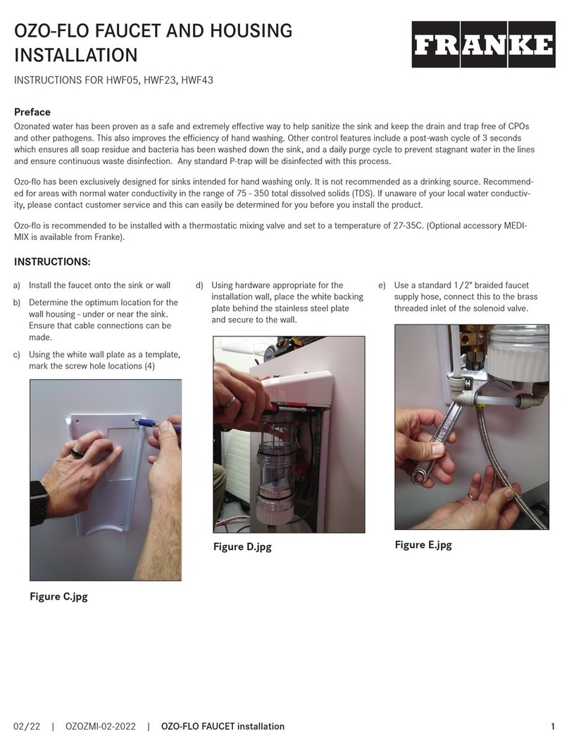
Page 2
MT04-001 AquariTherm Tap (Manual) www.dartvalley.co.uk Page 3
MT04-001 AquariTherm Tap (Manual) www.dartvalley.co.uk
Revision No. MAQTIN16071301
Revision No. MAQTIN16071301
Page 1
Step 3 : Plumbing
Fitting the Solenoid Valve For Urinal Flushing
Isolate the local water supply and position the solenoid valve in a
position, as near to the cistern as possible and preferably upright
(shown below). Cut the supply pipe to required length and purge
any debris or swarf. Fit the Solenoid valve ensuring joints are
tightened and checked for leaks but do not use plumbing paste. In
the event of very low or high water pressure the manufacturer can
offer alternative solenoid valves under special request.
It is highly recommended that a water filter (not supplied) be fitted
prior to the solenoid valve to ensure reliable operation.
B
15mm O/D pipe
Aquari-Save
Minimum air gap between
top of cistern and end of
pipe 25mm
Cistern
Step 3 : Continued
Step 2 : Kit ContentsStep 1 : Safety First
These instructions relate to the use of the Aquari-Save only,
any external or ‘add-on’ parts will be supplied with separate
instructions.
During installation, do not expose electronics to dust, dirt or damp.
It is recommended that any plumbing is carried out by a qualified
plumber.
This product must be installed correctly as per these instructions
to perform correctly.
If the appliance is used by persons (including children) with
reduced physical, sensory or mental capabilities, or lack of
experience and knowledge, they must be given adequate
supervision or instruction concerning use of the appliance by a
person responsible for their safety.
Children should be supervised to ensure that they do not play with
the appliance.
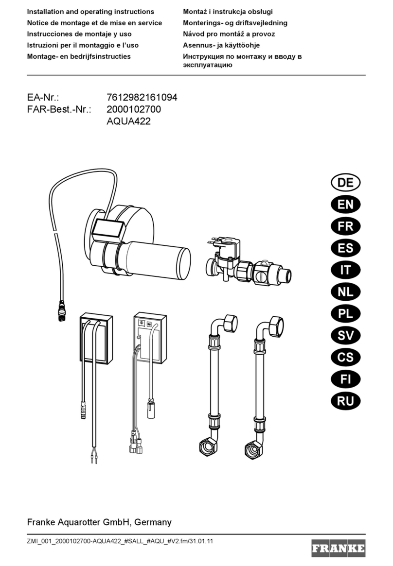
A typical kit will include; Aquari-Save unit, one solenoid valve
and a M3 Screw.
IMPORTANT: Please read these instructions carefully
and follow each stage in order!
*Not to scale
Control Box
(AC04-047)
6V DC Solenoid valve
AC17- 0 06
4
0RXQWLQJWKHFRQWUROER[ÀJ
3
Plumbing
Fitting the Solenoid Valve
Turn off the local water supply and locate the
solenoid valve in a position, as near to the
cistern as possible and preferably upright (as
shown in Fig 2). Cut the supply pipe and purge
any debris or swarf. Fit Solenoid valve ensuring
joints are tightened and checked for leaks. In
the event of very low or high water pressure the
manufacturer can offer alternative solenoid
valves under special request.
,WLVKLJKO\UHFRPPHQGHGWKDWDZDWHUÀOWHUQRW
VXSSOLHGEHÀWWHGSULRUWRWKHVROHQRLGYDOYHWR
ensure reliable operation.
Positioning the Control Box
The control box is rated IPX0 and should be
located in a dry location, away from extremes
of temperature and not exposed to dirt
dust or damp. The unit should be accessible
when required but not within easy reach of
unauthorised persons.
Standard Surface Mount Model
Remove the lid/cover and place in a safe
place. Select a convenient cable entry point
RQWKHER[WKHQGULOODQGÀWDQDSSURSULDWH
cable gland.
Drill and secure the control box base to the
required position on the ceiling with suitable
ÀWWLQJV)LWRQHHQGRIWKHYDOYHFDEOHLQWRWKH
box base and tighten cable gland, temporarily
UHÀWWKHFRQWUROER[OLGFRYHU
220-240V a.c 220-240V a.c
2
Kit contents
1
6DIHW\ÀUVW
These instructions relate to the use of the Timed
Urinal Control System only, any external or
‘add-on’ parts will be supplied with separate
instructions.
During installation, do not expose electronics
to dust, dirt or damp. It is recommended that
the electrical part of the installation be carried
RXWE\DTXDOLÀHGHOHFWULFLDQLQDFFRUGDQFH
with the latest electrical regulations. It is also
recommended that any plumbing is carried
RXWE\DTXDOLÀHGSOXPEHU
This is a sophisticated electronic device which
must be installed correctly to perform correctly.
If the appliance is used by persons (including
children) with reduced physical, sensory or
mental capabilities, or lack of experience and
knowledge, they must be given adequate
supervision or instruction concerning use of
the appliance by a person responsible for their
safety.
Children should be supervised to ensure that
they do not play with the appliance.
IMPORTANT: Please read these instructions
carefully and follow each stage in order!
Your kit will include the Timed Urinal Control
Box shown in Fig 1, one solenoid valve and a
lithium 6-volt battery. Alternatively you may
have a power supply, which will need to be
connected to a mains 240V output point.
The water pressure needs to be 0.5 bar
minimum to 8 bar maximum. If your water
pressure is outside these limits, please contact
manufacturer for assistance.
220-240V a.c 220-240V a.c
Page 3Timed Urinal Control System - Version. INUR002 v2.1 200612
Standard surface mount
Timed Urinal Control Box
Solenoid valve Lithium battery
Optional 6-volt DC
power supply (Fig. 1)
15mm O/D pipe
Cable to sensor
Minimum air gap between top of
cistern and end of pipe 25mm
Filter
Cistern
(Fig. 2)
(Fig. 3)
9
)DXOWÀQGLQJ
8
Test mode
With all the switches of the 4 way switch in
the ‘off’ position, the unit is set to test mode.
After power up/reset the valve will open for
5 seconds and will remain open for a period
set by 6 way dip switches, or if all switches are
in the off position, then it will be the default
5 seconds. This cycle will then repeat after 5
seconds and continue to do so whilst still in
test mode. To exit test mode a time must be
set and the reset button pressed. The solenoid
valve will close.
If nothing happens check all connections, reset
board and try again.
1. VALVE WILL NOT OPEN OR CLOSE PROPERLY
Check valve supplied is suitable for the
on site pressure, if in doubt contact P+L
Systems Washroom for advice.
7KHVROHQRLGYDOYHKDVDÁRZGLUHFWLRQVR
ensure it is the right way round.
There maybe debris in the solenoid valve.
5HPRYHYDOYHDQGÁXVKXQGHUUXQQLQJ
WDSUHÀWDQGWHVW
2. CONTROL BOX WILL DO NOTHING
If possible check voltage from battery or
power supply unit, (6 volt DC required).
Control board may have locked up. With
power connected press reset and try
again.
Check fuse on control board. If blown
check wiring and contact P+L Systems
Washroom for replacement.
3. VALVE OPENS AND RUNS FOR A LONG PERIOD
BEFORE SHUTTING OFF.
Check wiring to the plug on solenoid,
it may be wired the wrong way round,
reverse wires if necessary.
Make sure all connections are correct and
tight.
220-240V a.c 220-240V a.c
Page 6Timed Urinal Control System - Version. INUR002 v2.1 200612
M3 x 35
(PP00-826)
Page 2
Power Input
The battery supplied has a simple 2 pin connector and great
care must be taken to connect it in polarity (see Fig.4).
The battery is premounted into the unit and isolated using a
battery isolation strip. At the end of the battery life, the battery
should be carefully removed from the unit and disposed of
according to the disposal instructions at the end of these
instructions. Replacement batteries can be purchased through
your supplier or direct from DVS (Refer to Step 8 for spares.)
Caution must be exercised with Lithium type batteries:
1. DO NOT attempt to recharge
2. DO NOT expose to naked flames
3. DO NOT ‘short circuit’ battery
4. DO dispose of battery with care
Valve Connection
In the event that the Aquari-Save unit becomes detached from
the valve Fig. 4 shows how to re-establish the connection of the
valve cable to the sensor board.
Connection to the coil must be made via the supplied spade
connectors as shown in Fig. 5.
Before you can program your Aquari-Save unit, first you must
navigate your programmer to the “System Menu” and scroll down to
the “Timed Flush Time” line. If your programmer shows “Selected”
you will be able to adjust the run time in the Aquari-Save menu, if
the menu displays “Measured”, you will get a 20 second fixed run
time. Use the key pad to change from “Measured” to “Selected” if
required. For instruction on how to program your unit please make
reference to the hand held programmer instructions (PP00-468)
AQUARI-SAVE
Run Time 2,5,10,15,20,30,40,50,60 Secs,
2, 3, 4, 5 minutes
Day Of Week Mon-Sun
First Flush At 00:00-23:45 (15min Increments)
Last Flush At 00:00-23:45 (15min Increments)
No of Flushes 0-40
Flushing On/Off
Test / Hygiene Flush
“Measured” Default
Fill Time 20 Secs
Step 4 : Wiring & Electrical
Optional DVS
Handheld Programmer
(AC01-001)
NOTE: Aquari-Save is not limited to flushing only and can
be used for other applications.
NOTE: The Aquari-Save does NOT come with a DVS
Handheld Programmer and must be purchased separately
Mixed Supply
Check Valve
2 Channel
Control Box
Pipework bypass to be
as short as is reasonably
practicable
Shower Head
Sensor
Valve
Aquari-Save
Step 5 : Continued Step 6 : Program Settings
Fig. 4
Brown
Blue
Fig. 5
+-
Preparing the Control Box
The control box is not IP rated and should be located in a dry
location, away from extreme temperatures and not exposed to
dirt dust or damp. The unit should be accessible when required
although not within easy reach of unauthorised persons.
Activation
Remove the lid/cover and place in a safe place. Pull the battery
isolation strip out of the box. This will engage the battery and
power up the unit.
Step 5 : Preparing The Control Box
Fitting the Solenoid Valve For Purging
