manuals.online logo
Brands
  1. Home
  2. •
  3. Brands
  4. •
  5. Franke
  6. •
  7. Plumbing Product
  8. •
  9. Franke DVS AquariTherm Tap Operating and maintenance manual

Franke DVS AquariTherm Tap Operating and maintenance manual

Page 8
MT04-001 AquariTherm Tap (Manual) www.dartvalley.co.uk
Revision No. MAQTIN16071301
The valve will require periodical servicing and cleaning, please
contact manufacturer for servicing.
Do not attempt to dismantle the valve if you are unfamiliar with
electronic solenoid valves.
- Check all connections (shown in Fig 2).
- Check fuse (Mains/PSU model only).
- Voltage too low. Check tap input voltage (PSU output voltage - 6v
DC).
- Voltage too low. Replace battery, CRP2 or DL223A Lithium Cell
only.
- Check / Clean all connectors (shown in Fig 3).
- Check for cable damage.
- For Mains/PSU models, disconnect PSU and reconnect after 30
seconds
- Check water is turned on.
- Check the solenoid valve is fitted correctly.
- Check valve operation.
- Check for dirt or debris in the solenoid valve.
- Water pressure is too high.
14.1 Tap operates in reverse
(Water runs when hand is moved away from sensing area and
stops when returned to sensing area). Reversed valve polarity
(contact manufacturer)
14.2 Tap operates intermittently
- Clean sensor lens (with nonabrasive materials only).
- Tap may be installed too close to an R.F. interference source).
- Tap may be installed too close to very bright lighting / highly
reflective surfaces.
- Water pressure too low for valve to operate reliably (minimum 0.5
BAR
14.3 Optional Parts
AT00 - 033 / 1m PSU cable extension
AT00 - 034 / 2m PSU cable extension
AT00 - 035 / 3m PSU cable extension
Warranty
The tap kit is guaranteed for 5 years from purchase against
defective material and assembly.
Support
For technical support please visit our technical pages on
our website at www.dartvalley.co.uk, contact us by email at
techsupport@dartvalley.co.uk or alternatively call us direct on
01803 529021.
13.1 General
In the absence of any other instruction or guidance on determining
the appropriate frequency of in-service testing, the following
procedure may be used:
a) 6-8 weeks after commissioning carry out the “In-Service Tests”
b) 12-15 weeks after commissioning carry out the “In Service Tests”
The results of the above tests may presence several possibilities:
a) If no significant changes (e.g. 1 K) in mixed water temperatures
are recorded between commissioning and 6 to 8 week
testing, or between commissioning and 12-15 week testing the
next in-service test can be deferred to 24 to 28 weeks after
commissioning.
b) If small changes (e.g. 1 to 2 K) in mixed water temperatures
are recorded in only one of these periods, necessitating
adjustment of the mixed water temperature, then the next
in-service test can be deferred to 24 to 28 weeks after
commissioning.
c) If small changes (e.g. 1 to 2 K) in mixed water temperatures are
recorded in both of these periods, necessitating adjustment
of the mixed water temperature, then the next in-service test
should be carried out at 18 to 21 weeks after commissioning.
d) If significant changes (e.g. > 2 K) in mixed water temperatures
are recorded in either of these periods, necessitating service
work, then the next in-service test should be carried out at 18
to 21 weeks after commissioning.
The general principle to be observed after the first 2 or 3 in-service
tests is that the intervals of future tests must be set to those which
previous tests have shown can be achieved, with no more than a
small change in mixed water temperature.
Fault Finding
13.2 Tap will not operate at all
- Check water is turned on.
- Check hot and cold feed connected correctly
- Check filters for debris
General Cleaning
Step 13 : Frequency of In-Service Tests
AquariTherm Tap (Auto)
Installation, Maintenance & Operating Instructions
Dart Valley Systems | Kemmings Close | Long Road | Paignton | Devon | TQ4 7TW | UK
T +44 (0)1803 529 021 | F +44(0)1803 559 016 | www.dartvalley.co.uk | techsupport@dartvalley.co.uk
IMPORTANT: Do not use abrasive materials or cleaners.
Only use soap and water or nonabrasive cleaners.
Step 14 : Solenoid Valve Servicing Step 2 : Kit ContentsStep 1 : Safety First
These instructions relate to the installation of the AT04-002
AquariTherm Tap (Automatic) only. Any external or ‘add-on’ parts
will be supplied with separate instructions.
Appropriate personal protective equipment must be worn when
installing, calibrating and commissioning this product.
It is recommended that any plumbing is carried out by a qualified
plumber. The electrical part of the installation must be carried out
by a qualified electrician in accordance with the latest electrical
regulations.
This is a sophisticated product which must be installed correctly to
perform correctly.
If the appliance is used by persons (including children) with
reduced physical, sensory or mental capabilities, or lack of
experience and knowledge, they must be given adequate
supervision or instruction concerning use of the appliance by a
person responsible for their safety.
Children should be supervised to ensure that they do not play with
the product.
A typical kit will include the following parts*:
Instruction Manual (x1)
IMPORTANT: Please read these instructions carefully
and follow each stage in order!
*Not to scale
AC17- 0 52 (x2)
AT00- 037
AC17- 0 06
AT00- 029
AT07- 082
PP00-797 220121
PP00-797 220121
AT00 - 122
MT04-006
PP00-360
PP00-359
AC02- 017
AT04-002 AquariTherm Tap - Automatic
Seperate Sensor
c/w Standard Mains Kit
Page 3
MT04-001 AquariTherm Tap (Manual) www.dartvalley.co.uk
Revision No. MAQTIN16071301
Page 2
MT04-001 AquariTherm Tap (Manual) www.dartvalley.co.uk
Revision No. MAQTIN16071301
4.5
50
30
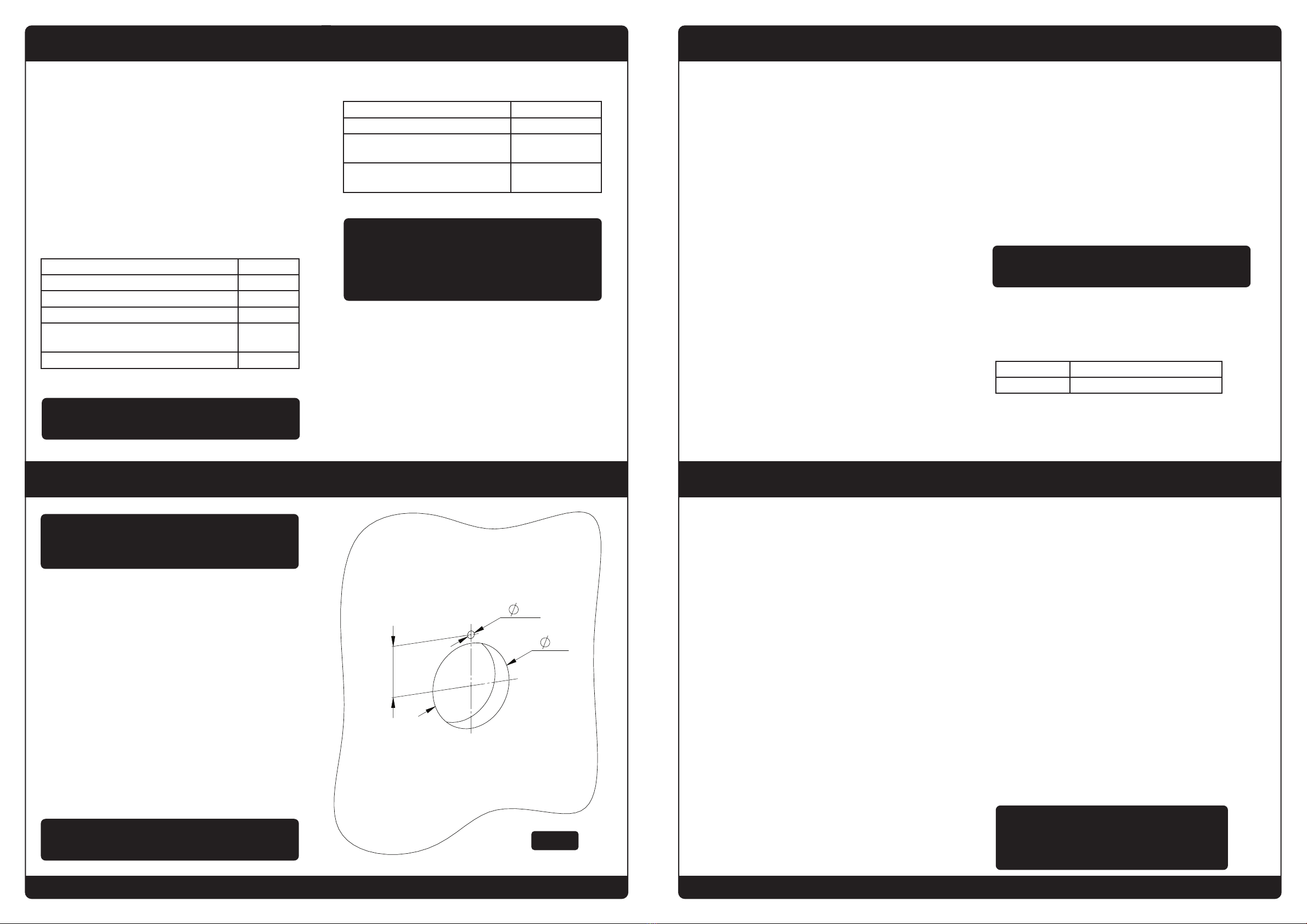
Step 4 : Preparation and Drilling
Step 3 : Introduction
The tap incorporates a thermoregulating cartridge to ensure users
of consistent water temperatures.
The tap is suitable, without modification, for all types of installation,
including pump boosted systems and mains pressure.
The valve has been designed and manufactured to comply with
NHS D08 requirements for washbasin applications up to 41ºC high
and high pressure designations.
The valve has been independently tested and approved as a Type 3
valve under the TMV3 scheme with the HP-WE designation of use.
Table 1: Technical Specification / Condition of Use for
Type 3 valves
Table 2: Mixed Water Temperature Approvals
NOTE: For washbasins, washing under running water
is assumed. The fitting of isolation valves is required as
close as is practicable to the water supply inlets of the
AquariTherm. Non-return valves and strainers are fitted
internally- see fig.13.
NOTE: Balanced pressures are desirable, but must be
maintained within the ranges above.
Maximum Static Pressure 10 Bar
Dynamic Pressure 1 to 5 Bar
Hot Supply Temperature 55-65 ºC
Cold Supply Temperature 5-20 ºC
Minimum Temperature Differential (Mix to Hot)
for Fail-Safe
10 ºC
Temperature Stability +/- 2 ºC
Code HP-WE
Application Washbasin
Mixed Water Temperature (at point of
discharge)
41 ºC
Operating Pressure High Pressure (1-5
Bar)
c) record the temperature of the mixed water at a smaller
draw-off flow rate, which shall be measured
d) isolate the cold water supply to the mixing valve and
monitor the mixed water outlet. If there is a flow stream
after 5 seconds then collect any water discharging into a
suitably graduated measuring vessel for 60 seconds; if the
volume of water collected is greater than 120ml then further
investigation is needed.
e) If there is no flow or the volume of water collected is less
than or equal to 120ml, then restore the cold water supply;
after 15 seconds, record the mixed water temperature.
f) record the equipment, thermometer etc. used for the
measurements
Table 3: Guide to maximum stabilised temperatures
recorded during site tests
Step 12 : In-Service Testing
11.1 Purpose
Since the installed supply conditions are likely to be different
from those applied in the laboratory tests it is appropriate, at
commissioning, to carry out some simple checks and tests on
each mixing valve to provide a performance reference point for
future in-service tests.
11.2 Procedure
Check that:
a) the designation of the thermostatic mixing valve matches
the intended application
b) the supply pressures are within the range of operating
pressures for the designation of the valve
c) the supply temperatures are within the range permitted for
the valve and by guidance information on the prevention of
legionella etc.
Adjust the temperature of the mixed water in accordance with
the manufacturer’s instructions and the requirement of the
application and then carry out the following sequence:
a) record the temperature of the hot and cold water supplies
b) record the temperature of the mixed water at the largest
draw-off flow rate
Step 11 : Method for Commisioning Thermostatic Cartridge
NOTE: The final stabilised mixed water temperature should
not exceed the values in Table 3
Application Mixed Water Temperature
Washbasin 41 ºC
7
We recommend the fitting of local hot & cold full flow isolation
valves prior to the tap if not already fitted.
Turn off hot & cold water supply. Cut pipework using a suitable
plumbers cutting tool, remove any sharp edges, locate isolation
valves on to pipes and tighten, make sure the new valves are in
the off position then turn the water back on, test for any leaks.
Using a bucket open each valve individually and purge water
through into the bucket this will remove any dirt left in the
pipework.
Refer to current HTM guidelines for tap positioning information,
also ensure adequate access is given under the Spigot to
operate integrated isolation valves.
Mark and drill a 50mm diameter hole in the wall panel where
the tap is to be located and a 4.5mm hole for the anti-rotation
pin (Fig. 1).
IMPORTANT: The tap is supplied with an anti-rotation pin.
Failure to fit the pin will result in void of warranty. Fig 1
IMPORTANT: Plumbing compound should not be used to
seal the pipework as oils leaching from the compound will
prevent the TMV from functioning correctly.
12.1 Purpose
The purpose of in-service tests is to regularly monitor and record
the performance of the thermostatic mixing valve. Deterioration in
performance can indicate the need for service work on the valve
and/or the water supplies.
12.2 Procedure
Using the same measuring equipment or equipment to the same
specification as used in the commissioning of the valve, adjust
the temperature of the mixed water in accordance with the
manufacturer’s instructions and the requirement of the application.
Carry out the following sequence:
a) record the temperature of the hot and cold water supplies.
b) record the temperature of the mixed water at the largest
draw-off flow rate.
c) record the temperature of the mixed water at a smaller draw-off
flowrate, which shall be measured.
If the mixed water temperature has changed significantly from the
previous test results (e.g.>1 K) 5), record the change and before
re-adjusting the mixed water temperature check:
a) that any in-line or integral strainers are clean.
b) any in-line or integral check valves or other anti-back siphonage
devices are in good working order.
c) any isolating valves are fully open.
With an acceptable mixed water temperature, complete the
following procedure:
a) record the temperature of the hot and cold water supplies
b) record the temperature of the mixed water at the largest
draw-off flow rate.
c) record the temperature of the mixed water at a smaller draw-off
flow rate, which shall be measured.
d) isolate the cold water supply to the mixing valve and monitor the
mixed water temperature.
e) record the maximum temperature achieved as a result of (d) and
the final stabilised temperature.
f) record the equipment, thermometer etc. used for the
measurements.
If at step (e) the final mixed water temperature is greater than the
values in Table 1 (Step 3) and / or the maximum temperature
exceeds the corresponding value from the previous results by more
than about 2 K, the need for service work is indicated.
NOTE: In-service tests should be carried out with a frequency,
which identifies a need for service work before an unsafe water
temperature can result. In the absence of any other instruction
or guidance, the procedure described in Annex Fof D 08 may be
used - Annex F of D 08 (informative)
Page 4
MT04-001 AquariTherm Tap (Manual) www.dartvalley.co.uk Page 5
MT04-001 AquariTherm Tap (Manual) www.dartvalley.co.uk
Revision No. MAQTIN16071301
Step 9: Continued...
1. Using a 4mm slotted screwdriver, insert through the hole
and locate the setting screw (Fig 11).
2. Turn the setting screw clockwise to reduce the
temperature and counter clockwise to increase the
temperature.
3. Only adjust by a small amount, a 1/4 turn in either
direction should be sufficient to reach the desired
temperature.
4. When desired temperature has been set, replace the
spindle plug.
Refit the penny washer, retainer screw and the screw cover.
Fig 11
Step 10: Maintenance and Servicing
Step 6 : Mounting the Spigot and Plumbing
Step 5 : Typical Schematic
Page 6Page 3
Fig 12
Fig 14 Fig 15
Fig 13











































Mount the spigot to the wall surface and secure with the nut
and washer provided (Fig 3).
Connect the HOT and COLD water supply to the spigot using the
copper tails provided with the kit (Fig4) taking care to ensure the
HOT and COLD supply are connected correctly as indicated by
the coloured indicators. It is important that all pipework should be
thoroughly flushed through before connecting the tap.
Check ball valves on wall spigot are in the closed position as
Fig. 2.
Fig 2
Fig 3
Fig 4



















HOT
COLD
INCREASE
MAX TEMPERATURE
The thermostatic cartridge should give many years of trouble –free
service, but in the event of failure or where routine maintenance is
required servicing is straightforward.
10.1 Filter and Check Valve
To service the internal filter and check valve the main tap body
needs to be removed from the spigot.
Using a 6mm slotted screw driver isolate the hot water supply by
turning the integrated isolation valve 90 clockwise (Fig 7.1).
Follow the same procedure for the cold supply.
Remove the retainer screw (Fig. 6 and 6.1).
The main tap body can now be removed to enable servicing of the
filter and check valve.
The filter cartridges (Fig 13) can be removed from the body of the
tap (Fig 12).
The filters can be removed and replaced. Service kits are
available, contact sales@dartvalley.co.uk or call (01803) 529021.
10.2 Thermostatic Cartridge
To remove the thermostatic cartridge, isolate water and power
supply, then remove screw cover and unscrew the retaining screw
and remove penny washer, top cap and limit ring (Fig 9). Unscrew
the cartridge retaining nut and pull the cartridge out. Clean or
replace cartridge as necessary. Be sure to re-fit the cartridge
with its locating lug pointing forwards (Fig 14). Refit the cartridge
retaining nut and tighten to 35Nm (Fig 15). Without the limit ring
fitted, place the Top Cap in position. Reactivate the cold and hot
water supplies.
Gently turn the Top Cap clockwise until the water just stops
flowing, then turn counterclockwise through approximately 90
degrees. Remove the Top Cap and position the limit ring on the
cartridge retaining nut, as shown (Fig 16).
Refit the Top Cap and secure the with retainer screw and penny
washer. Refit screw cover so that the logo is square.
Fig 16
LIMIT STOPS
½ TURN (35NM)
REDUCE
MAX TEMPERATURE
3 AMP FUSED SPUR
POWER SUPPLY
COLD WATER
SUPPLY
HOT WATER
SUPPLY
ISOLATOR
FILTER
SOLENOID
VALVE
Y-SPLITTER
LEAD
DUAL VALVE
ACTUATOR
AQUARITHERM
TAP
PROGRAMMABLE
SENSOR
Please reference AC02-017 instructions for sensor operation.
Available on www.dartvalley.co.uk
Page 6
MT04-001 AquariTherm Tap (Manual) www.dartvalley.co.uk Page 7
MT04-001 AquariTherm Tap (Manual) www.dartvalley.co.uk
Revision No. MAQTIN16071301
Step 8 : Checking the TMV Temperature
Step 9 : TMV Temperature Calibration and Setup
Ensure water supply is isolated and power running to the tap is
turned on.
Using a 6mm slotted screw driver the cold water supply is
activated by turning the integrated water isolation valve 90º
counter clockwise (Fig 7.1). Follow the same procedure for the
hot supply.
Fig 7 Fig 7.1
Fig 8
Hold a thermometer under the outlet (Fig8) of the tap, this
should start the flow of water from the tap allow the tap to
run and the water to get up to temperature and settle (Fig 8).
The temperature should be set at 41˚C.
If the temperature is outside the range 40-42˚C the TMV
should be calibrated, as per Step 9.
Step 6 : Continued...
Using a 2.5mm Allen key fit retainer screw (Fig. 6 and 6.1).
Page 4Page 5
Isolate the hot and cold water supply.
Carefully remove screw cover, retainer screw and penny washer,
only (Fig 9).
Remove the spindle plug (in middle of spindle head) (Fig 10).
Fig 9
Fig 10



















Fig 6.1
Fig 6
Fit main tap body to wall spigot (Fig. 5). Ensure body is fully
located over the spigot.
Fig 5.1 shows the body correctly located whereas the body has
not been fully engaged in Fig 5.2.
Fig 5.1
Fig 5.2






































Step 7: Activating the water & power supply
SCREW COVER
RETAINER SCREW
PENNY WASHER
TOP CAP
LIMIT RING
CARTRIDGE RETAINER NUT
SPINDLE PLUG






































Fig 5

This manual suits for next models

1

Other Franke Plumbing Product manuals

Franke AQCT0027 User manual

Franke

Franke AQCT0027 User manual

Franke KEP ACSL Series User manual

Franke

Franke KEP ACSL Series User manual

Franke ANMX Series Manual

Franke

Franke ANMX Series Manual

Franke CHILLOUT FF4900 User manual

Franke

Franke CHILLOUT FF4900 User manual

Franke 7612982131844 User manual

Franke

Franke 7612982131844 User manual

Franke F5ET2003 User manual

Franke

Franke F5ET2003 User manual

Franke F3 Series User manual

Franke

Franke F3 Series User manual

Franke F3 Series User manual

Franke

Franke F3 Series User manual

Franke PESCARA PFD4400 User manual

Franke

Franke PESCARA PFD4400 User manual

Franke F5 Series User manual

Franke

Franke F5 Series User manual

Franke F5LT2024 2030066543 User manual

Franke

Franke F5LT2024 2030066543 User manual

Franke FF-1600 Series User manual

Franke

Franke FF-1600 Series User manual

Franke F5SM1007 User manual

Franke

Franke F5SM1007 User manual

Franke F3EV2001 User manual

Franke

Franke F3EV2001 User manual

Franke AQRM170 User manual

Franke

Franke AQRM170 User manual

Franke F5 F5ST2004 User manual

Franke

Franke F5 F5ST2004 User manual

Franke SD100 User manual

Franke

Franke SD100 User manual

Franke FMA 2.0 607 User manual

Franke

Franke FMA 2.0 607 User manual

Franke AQCT0043 User manual

Franke

Franke AQCT0043 User manual

Franke F5EM1011 User manual

Franke

Franke F5EM1011 User manual

Franke F3 Series User manual

Franke

Franke F3 Series User manual

Franke URBAN UBG 610-56 User manual

Franke

Franke URBAN UBG 610-56 User manual

Franke AG100 User manual

Franke

Franke AG100 User manual

Franke RODX605 User manual

Franke

Franke RODX605 User manual

Popular Plumbing Product manuals by other brands

Grohe 36 322 installation instructions

Grohe

Grohe 36 322 installation instructions

Gessi VIA MANZONI 39342 manual

Gessi

Gessi VIA MANZONI 39342 manual

miseno MNO611 CP quick start guide

miseno

miseno MNO611 CP quick start guide

NOVUM CASABLANCA FR207/60 Installation

NOVUM

NOVUM CASABLANCA FR207/60 Installation

Delabie TEMPOFLUX manual

Delabie

Delabie TEMPOFLUX manual

CANTERBURY AGORA Z2314-45IN manual

CANTERBURY

CANTERBURY AGORA Z2314-45IN manual

Whitehall WH3740BAR Installation, operation and maintenance manual

Whitehall

Whitehall WH3740BAR Installation, operation and maintenance manual

American Standard MONTERREY 6545 Series installation instructions

American Standard

American Standard MONTERREY 6545 Series installation instructions

Kessel Linearis Comfort installation instructions

Kessel

Kessel Linearis Comfort installation instructions

Toshiba LF602F instruction manual

Toshiba

Toshiba LF602F instruction manual

Enlighten Sauna Sierra-3 user manual

Enlighten Sauna

Enlighten Sauna Sierra-3 user manual

noken ZEN 100263141 N343120136 manual

noken

noken ZEN 100263141 N343120136 manual

Hans Grohe Talis E2 31687000 Instructions for use/assembly instructions

Hans Grohe

Hans Grohe Talis E2 31687000 Instructions for use/assembly instructions

Symmons 3DIVBODYNSSRT Operation & maintenance manual

Symmons

Symmons 3DIVBODYNSSRT Operation & maintenance manual

American Standard Afwall ADA Retrofit 1.6 GPF Flushometer Toilet... Specification sheet

American Standard

American Standard Afwall ADA Retrofit 1.6 GPF Flushometer Toilet... Specification sheet

VITRA Vitrus 770-5770-01 Installaton guide

VITRA

VITRA Vitrus 770-5770-01 Installaton guide

Betts CH46955SST Installation and maintenance manual

Betts

Betts CH46955SST Installation and maintenance manual

Kalia EXKI KF1548 Installation instructions / warranty

Kalia

Kalia EXKI KF1548 Installation instructions / warranty

manuals.online logo
manuals.online logoBrands
  • About & Mission
  • Contact us
  • Privacy Policy
  • Terms and Conditions

Copyright 2025 Manuals.Online. All Rights Reserved.