Franklin Fueling Systems TS-RA1 User manual

TS-RA1, TS-RA2 and TS-RK
Tank Overll Alarms
Installation Guide
franklinfueling.com
3760 Marsh Rd. • Madison, WI 53718, USA
Tel: +1 608 838 8786 • Fax: +1 608 838 6433
Tel: USA & Canada +1 800 225 9787 • Tel: UK +44 (0) 1473 243300
Tel: Mex 001 800 738 7610 • Tel: DE +49 6571 105 308 • Tel: CN +86 10 8565 4566

1
Important Safety Messages
FFS equipment is designed to be installed in association with volatile hydrocarbon liquids such as gasoline and diesel fuel. Installing or
working on this equipment means working in an environment in which these highly ammable liquids may be present. Working in such
a hazardous environment presents a risk of severe injury or death if these instructions and standard industry practices are not followed.
Read and follow all instructions thoroughly before installing or working on this, or any other related, equipment.As you read this guide,
please be aware of the following symbols and their meanings:
This symbol identies a warning. A warning sign will appear in the text of this document when a potentially hazardous
situation may arise if the instructions that follow are not adhered to closely. A potentially hazardous situation may
involve the possibility of severe bodily harm or even death.
This is a caution symbol. A caution sign will appear in the text of this document when a potentially hazardous
environmental situation may arise if the instructions that follow are not adhered to closely. A potentially hazardous
environmental situation may involve the leakage of fuel from equipment that could severely harm the environment.
This symbol identies an electrical danger. An electrical danger sign will appear in the text of this document when a
potentially hazardous situation involving large amounts of electricity may arise if the instructions that follow are not
adhered to closely. A potentially hazardous situation may involve the possibility of electrocution, severe bodily harm, or
even death.
Follow all applicable codes governing the installation and servicing of this product and the entire system.
Always lock out and tag electrical circuit breakers while installing or servicing this equipment and any
related equipment. A potentially lethal electrical shock hazard and the possibility of an explosion or re from
a spark can result if the electrical circuit breakers are accidentally turned on during installation or servicing.
Please refer to the Installation and Owner’s Manual for this equipment, and the appropriate documentation
for any other related equipment, for complete installation and safety information.
Follow all federal, state and local laws governing the installation of this product and its associated systems.
When no other regulations apply, follow NFPA codes 30, 30A and 70 from the National Fire Protection
Association. Failure to follow these codes could result in severe injury, death, serious property damage and/
or environmental contamination.
When the Fuel Management System system is used to monitor tanks containing gasoline or other ammable
substances, you may create an explosion hazard if you do not follow the requirements in this manual
carefully.
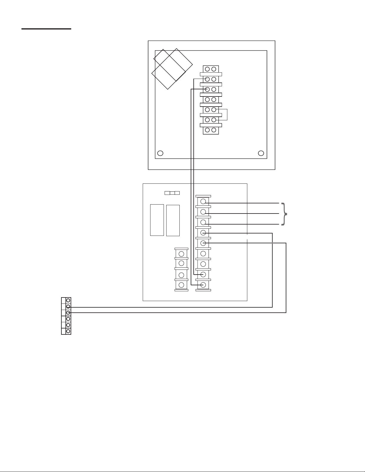
All wiring from probes or sensors to the console must be run in conduit separate from all other wiring.
Failure to do so will create an explosion hazard.
Product Overview and Theory of Operation
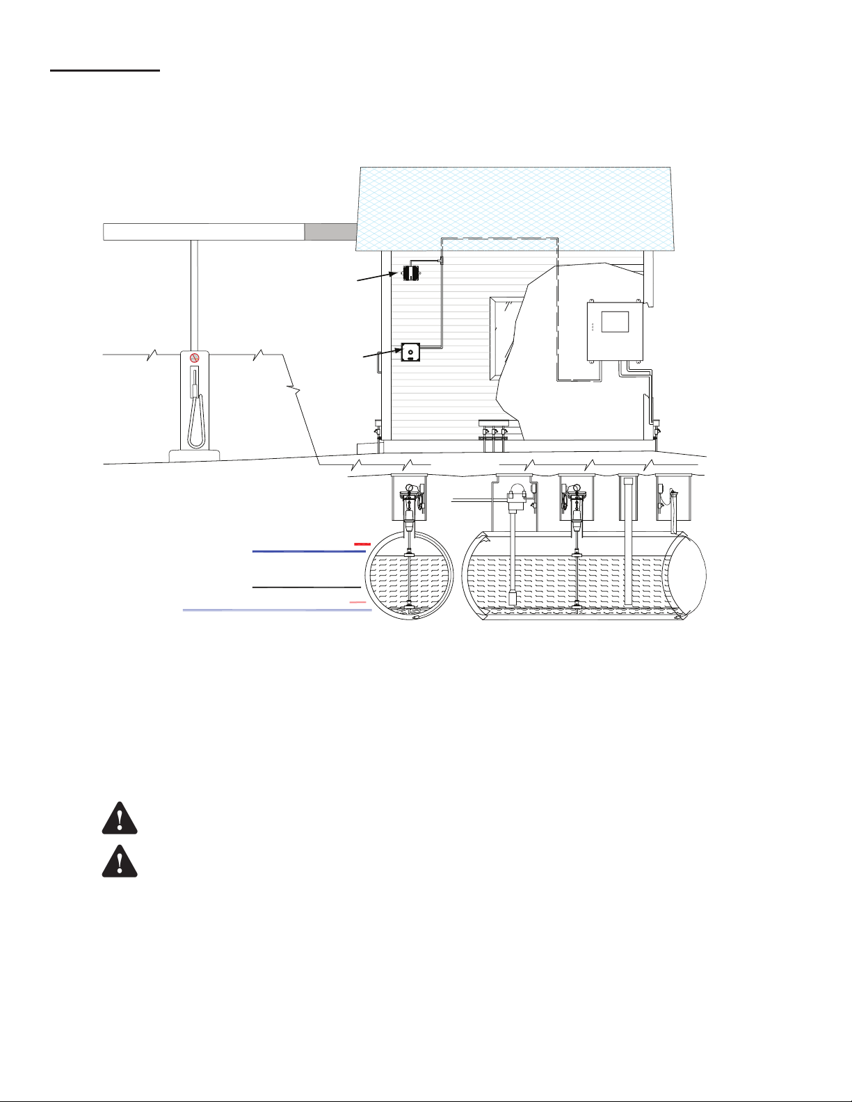
The TS-RA1, and TS-RA2 are remote audible and visual alarm units that are used with Fuel Management System consoles. The TS-
RA1, TS-RA2, and the TS-RK Tank Overll Alarm and Alarm Acknowledge units are mounted near the tank lling site. If the tank
product level reaches the FMS overll alarm setpoint, then the Tank Overll Alarm will become active. An active Tank Overll Alarm
alerts the tank lling attendant to immediately stop the lling operation before a spill occurs. The TS-RK is an optional remote alarm
acknowledge unit. This unit gives the tank lling attendant the means to silence a Tank Overll Alarm at the lling site. The TS-RK is
required when a TS-RA1 or TS-RA2 is connected to a T5 series Fuel Management System console or a Colibri Automatic Tank Monitor.
When in an alarm condition, depressing the acknowledge button on the TS-RK will silence the Tank Overll Alarm at the tank lling site.
Alarm Specications
The TS-RA1 is a standard intensity, remote alarm device that has a useful signal range up to 50 feet.
Ratings
Input Power 115 VAC (96 to 132vac), 60Hz @ 0.125 amps Maximum
Operating Temperature Range –31 to 150 °F
Humidity Range Up to 95% humidity
Signal outputs Visual (low intensity incandescent lamp) & audio tone (85 dB @ 10 feet)
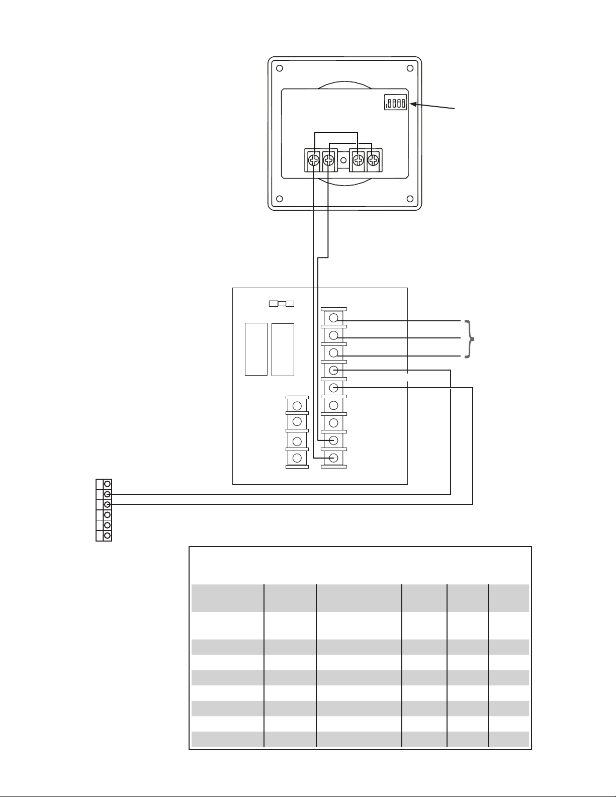
The TS-RA2 is alarm device that has a strobe-light, and eight user-selectable output tones with two user-selectable sound intensities.
In the high-intensity mode, the TS-RA2 has a useful signal range up to 200 feet.
Ratings
Input Power 115 VAC (96 to 132vac), 60Hz @ 0.125 amps Maximum
Operating Temperature Range –31 to 150 °F
Humidity Range Up to 95% humidity
Signal outputs Visual strobe (15 Candela), and audio tone (99dB to 75 dB @ 10 feet).
When properly installed, wired, and programmed, this alarm system will help prevent dangerous fuel spills, environmental
contamination, and cleanup costs.
Danger
Warning
Warning
Warning
Warning
Warning
Caution

2
Installation
Overview
The mounting location of TS-RA1, TS-RA2, TS-RK units should be based on: cable run length, ease of conduit routing,
alarm light visibility, alarm horn audible range limitations, and the distance away from hazardous areas. In addition, the
following limitations and requirements must be met.
TANKOVERFILL ALARM
LOW Limit
(Reorder) setpoint
HIGH Limit
(Tank full) setpoint
(high)WATER
Limit setpoint
HI HI Limit
(Tank Overfill) setpoint
LO LO Limit setpoint
HAZARDOUS
AREA
TS-RK
Alarm Acknowledge
Unit
NON-HAZARDOUS
AREA
TS-RA1, or TS-RA2
Tank Overfill Alarm
(TS-RA2 shown)
FMS
Console
NON-HAZARDOUS
AREA
Tank Filling Site
HAZARDOUS
AREA
MODELTS-RK
SACO,MAINE04072
INTELLIGENTCONTROLSINC.
ACKNOWLEDGE
74INDUSTRIALPARKROAD
SACO,MAINE04072
INTELLIGENTCONTROLS
74INDUSTRIALPARKRD.
TANKOVERFILL ALARM
MODELTS-RA2
Figure 1: TS-RA and TS-RK Installation Overview
• The location of the Tank Overll Alarm and Alarm Acknowledge unit enclosures must be less than 1000 feet away from
the 120 VAC electrical power (source) panel.
• The TS-RA1, or TS-RA2 Tank Overll Alarm unit should be mounted near the fuel tank lling area.
• The alarm light must be visible and the alarm horn must be audible at the fuel tank lling area.
•
These units should be mounted in a protected location that minimizes exposure to direct sunlight, snow and rain.
• The TS-RK Tank Overll Alarm Acknowledge unit should be accessible to the tank lling attendant. Access to the TS-RK
from the lling area must be clear with no obstructions.
DO NOT install the Tank Overll Alarm, or Alarm Acknowledge units in a volatile, combustible, or
explosive atmosphere. Failure to do so may create an explosion hazard.
Run wiring from the Tank Sentinel console to the TS-RA1 / TS-RA2 Tank Overll Alarm, and TS-RK
Alarm Acknowledge units in separate conduit apart from any other wiring. All conduits must enter
through supplied non-intrinsically safe enclosure knockouts only. Failure to do so may create an
explosion hazard.
Warning
Warning

3
Mounting the Units
• Mount the TS-RA1, and/or TS-RK units through the four (4)
mounting holes provided in the case under the front cover.
4.22"
107 mm
Internal View (Cover Removed)
EXT
ALARM
CON.
110 VAC
(NEUT)
(LINE)
110 VAC
GND
(4) Holes for
#8-32 Mounting Screws
4.22"
107 mm
G1
(Flasher)
Figure 2: TS-RA1 Mounting Details
4.22"
107 mm
4.22"
107 mm
Internal View (Cover Removed)
(4) Holes For
#8-32 Mounting Screws
NEUTRAL1-2
LATCH
MODE
ACKN
SWITCH
REMOTE
ALARM
SIGNAL
FLASH
SHUNT
FLASH
DRIVE
OUTPUT
OUTPUT
RETURN
GROUND
1-7
1-9
1-8
1-6
1-5
1-4
1-3
F1 LINE1-1
2-1
2-2
2-3
2-4
Figure 3: TS-RK Mounting Details
• Mount the TS-RA2 unit through the two (2) mounting
holes provided.
0.25 DIA (6.4 MM)
(2) HOLES
5.0"
127 mm
Figure 4: TS-RA2 Mounting Details
Wiring the Units
Materials Required
• Wire: 18 to 14 AWG, 300 Volt, type TFFN, THWN,
or THHN (Note: THHN is not available in 18 AWG).
Recommended insulation colors are black, white, green,
and blue.
• Conduit: 1/2 inch, or 3/4 inch (the TS-RA2 has a 1/2 inch
NPT for threaded conduit / tting).
•
Fittings: for conduit used, and conduit hold-down clamps.
• Sealant: waterproof conduit, ttings, tting threads, and
conduit accesses to the building.
• Fasteners: appropriate for the wall construction involved.
Refer to the schematics on the following page for
connection information.

4
1-1 LINE
1-2 NEUTRAL
2-1
2-2
2-3
2-4
1-6 FLASH DRIVE
1-7 FLASH SHUNT
1-8 OUTPUT
1-9 OUTPUT RETURN
1-3 GROUND
1-4
1-5
REMOTE ALARM SIGNAL
ACKN
SWITCH
LATCH
MODE
Console Rel
ay Outputs
NC1
C1
NO1
NC2
C2
NO2
TS-RA1
TS-RK
110 VAC
(LINE)
110 VAC
(NEUT)
GND
EXT
ALARM
CON.
To 110 VAC
Power Supply
2AG 3A Fuse
TS-RK and TS-RA1 Wiring Schematic
Schematics

5
1-1 LINE
1-2 NEUTRAL
2-1
2-2
2-3
2-4
1-6 FLASH DRIVE
1-7 FLASH SHUNT
1-8 OUTPUT
1-9 OUTPUT RETURN
1-3 GROUND
1-4
1-5
REMOTE ALARM SIGNAL
ACKN
SWITCH
LATCH
MODE
NC1
C1
NO1
NC2
C2
NO2
TS-RA2
TS-RK
To 110 VAC
Power Supply
N STB L
N AUD L
SW1
1 2 3 4
O
N
2AG 3A Fuse
Console Rel
ay Outputs
TS-RK and TS-RA2 Wiring Schematic
TS-RA2 SW1 Switch Position Settings
(factory settings are shown in bold italic)
Sound Ouput
Level
Position 1 Tone Pos. 2 Pos. 3 Pos. 4
High dB ON Horn
(continuous)
ON ON ON
Standard db OFF Bell ON OFF ON
March Time Horn OFF OFF ON
Code-3 Horn ON ON OFF
Code-3 Tone OFF ON ON
Slow Whoop OFF ON OFF
Siren ON OFF OFF
HI/LO OFF OFF OFF
See Table below

6
Setup and Operation
Set up the console so that the alarms operate properly:
1. Identify the relay that is being used to activate the overll alarm equipment.
2. Navigate to the setup programming of that relay.
3. Conrm that the relay is programmed according to the following:
• Name: Overll Alarm Relay (or similar).
• Enabled: Yes
• Type: Alarm
• Polarity: Normal
• Logic: OR Logic
• Physically Wired As: Normally Open
• Number of inputs: 0
NOTE: If you have a legacy console, refer to the associated programming manuals for specic information.
4. Make sure the rule activates the overll alarm equipment when a HIGH or HIGH HIGH tank alarm occurs. Go to
the Rules section of programming:
• Rule: Overll Alarm Activate (or similar)
• Name: Overll Alarm Activate (or similar)
• Enabled: Yes
• Events
• Event: Type Alarm Occurred
• Category: FMS
• Device: Tank
• Device ID: Any
• Code: High high product level
Actions
• Action Type: Relay
• Module: Power Supply Module
• Channel: Overll Alarm Relay
• Action: One Pulse
• Duration: 2
NOTE: Legacy consoles that do not have the One Pulse option must incorporate two seperate actions. One action to
activate the relay, the second action to deactivate the relay.
NOTE: Verify that the code you select sounds the alarm at the correct volume/limit set for each tank.
NOTE: Verify that the code you select refers to the correct High High or High product threshold. You can conrm the units
in which the High and High High thresholds are measured under Fuel Management Systems/High Product Limit.
5. Force the tank into the High or High High Alarm by manually raising the product oat beyond the threshold and
conrming the Overll alarm sounds. Press the acknowledge button on the TS-RK to silence the alarm.
Testing the Alarm Wiring
Use the following procedure to verify that the tank Overll Alarm is wired correctly. If the Setup and Operation procedure
does not produce an Overll Alarm, use the following procedure to verify that the issue is not caused by improper wiring.
1. Go to System/Diagnostic/Relay Status.
2. Select the Activate/Deactivate checkbox for the Overll Alarm Relay (or a similar relay). The Active indicator
becomes GREEN for the associated relay.
3. Make sure the Overll Alarm is activated.
a. If the Overll Alarm is activated, the wiring is correct. Clear the Overll Alarm Relay checkbox to deactivate
the relay. Press the acknowledgment button on the TS-RK to silence the alarm.
b. If the Overll alarm is not activated, there is an issue with the wiring. Clear the Overll Alarm Relay checkbox
to deactivate the relay. Consult the TS-RA1, TS-RA2, TS-RK installation manual for information about proper
wiring.
NOTE: If you have a legacy console, refer to the associated programming manuals for information about manually
activating relays.

© FFS 2018 000-1027 r7
This manual suits for next models
2
Table of contents
Other Franklin Fueling Systems Other manuals