2BLITZ www.freeair.cz
BLITZ
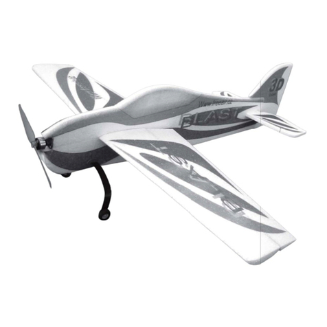
Dear customer, congratulations on the purchase of the Blitz model. To enjoy building and flying
the model most, please read carefully the building instructions before you begin and make
sure that you understand the building process.
DESCRIPTION OF THE MODEL:
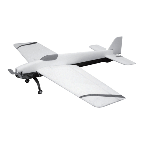
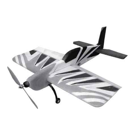
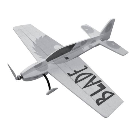
The Blitz model is completely made of the expanded polypropylene (EPP) and carbon
composite components. Its light weight (from 170 grams) makes it an ideal model for both
indoor and calm-weather outdoor flying. It is suitable not only for experienced pilots, but also
for the first introduction to the model aerobatics.
We suggest that you use our Microtex AC motors, either the Microtex 20/8/14 (for
two LiPol cells) or 20/8/18 (for 3 LiPol cells). Thanks to the model‘s well-engineered design
the assembly would take only about 90 minutes. All parts fall in place, puzzle-like, and all
compartments and openings for the RC equipment are already there, too. You can order
the model in a painted version, or you can decorate it yourself, using e.g. the textile spray
paints. Only your fantasy and the weight of added paint are the limits to the scheme you may
choose.
BUILDING:
The whole model is built using the medium-thick CyA glue. Start with gluing the side
panels to the fuselage as shown on (Fig. 1). Once this is done, insert (do not glue) the servos
to the prepared openings in the fuselage (Fig. 2). If different servos are used, modify the
openings accordingly. Once the servos are in place, glue the other fuselage side panel (Fig.
3) in place. Do not glue the servos because the fuselage structure fixes them in place. Glue
in place the bottom wing (Fig. 4) and the wing struts (Figs. 5 and 6). Glue together the top
wing halves (Fig. 7) and then glue the assembly to the fuselage (Figs. 8 and 9). Glue in
place the slab elevator bushings (Figs. 10 and 11). Using the carbon tube as a core drill, drill
the hole in the elevator (Fig. 12). According to the (Fig. 13) insert the carbon tube into the
assembled bushings, threading onto it also the elevator control lever; at the moment do not
glue the control lever in place. Glue the elevator to its carbon tube axe (Fig. 14), taking care to
prevent glue from coming in contact with parts that must remain movable. Cut the groove for
the hinges of the rudder and glue the hinges in place. (Fig. 15). Then glue the rudder control
lever in place (Fig. 16).
Using the (Fig. 17) as a guide, glue in place the motor mounting and its reinforcement
(Fig. 18). Drill a 2mm hole in the undercarriage leg and attach the wheel to it, using the Figs.
19 and 20 as a guide. Glue the wheel pant in place (Fig. 21) and insert the undercarriage into
the fuselage. Then attach the other wheel and its pant and glue the undercarriage assembly to
the fuselage. Check that the model sits square on the undercarriage on the ground before the
glue cures fully!!
Attach the motor (Fig. 22) and, using the 1,6mm drill, open up the holes in the support
pillars to hold the elevator and rudder push-pull rods (Fig. 23). Slide the pillars onto the rod
and glue the pillars to the fuselage (Fig. 24); set the elevator to neutral position and glue the
control lever in place. In the same way glue the pillars onto the rudder control rod (Fig. 25).
Take the aileron joiners and glue them in place as per (Fig. 26); install the interconnecting rod
(Fig. 27).
Glue the aileron extension lever and secure it by a set screw (Fig. 28), then insert the servo
into the wing and attach in place by screws (Fig. 29).
Cut the grooves into the ailerons (Fig. 30), then glue into them the levers. Install the aileron
control rods (Fig. 31) and solder the controller (Fig. 32). Glue the wing cross braces (Figs. 33
and 34). The centre of gravity should be 60 mm from the top wing‘s leading edge (Fig. 35).
Balance the model by shifting the battery so that the C of G is in the required position and then
cut out the battery compartment above the side stiffener.
Your Blitz is now complete. Set the deflection of the control surfaces to maximum, adding
exponential displacement as required/used to, taking into consideration your own piloting
skills.
When finishing the model in colour, consider the presumable weight increase, caused by adding
the paint; bearing this in mind, any paint could be used. We recommend the alcohol-based
permanent markers or the spray - on textile colours as the lightest.
To tune-up the model, you may order the wing leading edge liner (slows the model down and
improves its handling), or a set of floats for water operation.
Many happy landings!
Your FreeAir.
PARTS LIST
Part name Pcs Part name Pcs
Fuselage of EPP 3 Undercarriage wheel 2
Elevator and rudder control rod 2 Set of bolts 2
Wing of EPP 3 Set of nuts 4
Aileron, elevator and rudder of EPP 3 Undercarriage carbon leaf spring 1
Undercarriage base 2 Push-pull rod lever 3
Aileron push-pull rod 2 Motor mounting 1
Plastic hinge 2 Elevator joiner (carbon 5x100 mm) 1
Aileron joiner (1,6x150mm) 2 Aileron joiner lever 4
Plastic tube (3x20 mm) 4 Instructions 1
Motor bulkhead 1 EPP wing stiffeners 2
Undercarriage wheel pant (EPP) 2 Slab elevator set (bushings and control
lever) 1
You will need the following tools and materials:
CyA glue, CyA glue accelerator, 1,6 and 2 mm dia drill bit, sharp (modelling) knife, sandpaper,
3M contact glue in a spray can. To complete the model you need the following: Penta receiver
(MZK), servos (Dimond), controller (TMM 0710-3), battery pack (2-3 LiPol cells of 720-1500
mAh), motor (Microtex 20/5/18 or 20/8/18), propeller.
