2NEMO www.freeair.cz
NEMO
Dear customer, congratulations on the purchase of the Nemo model. To enjoy building and
flying the model most, please read carefully the building instructions before you begin and
make sure that you understand the building process.
DESCRIPTION OF THE MODEL:
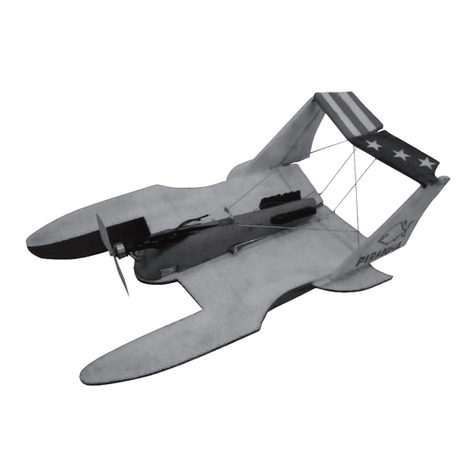
The Nemo model is completely made of the expanded polypropylene (EPP). Its light
weight (from 280 grams) makes it an ideal model for a calm-weather waterside flying at a
pond or a lake. Thanks to its power it is able to take off even from a mown lawn. It is suitable
not only for averagely experienced pilots, but, if you set up the maximum throw of the control
surfaces, it would fly some basic aerobatic figures as well - a loop and a roll. You can choose
as its powerplant our Microtex AC motors, either the Microtex 20/5/14 (for two LiPol cells) or
20/8/18 (for 3 LiPol cells). Or, instead of the AC motors, you can use the Speed 280 series
of motors. Thanks to the model‘s well-engineered design the assembly would take only about
90 minutes. All parts fall in place, puzzle-like, and all compartments and openings for the RC
equipment are already there, too. You can order the model in a coloured version, or you can
decorate it yourself, using e.g. the spray-on textile paints. Only your fantasy and the weight of
added paint are the limits to the scheme you may choose.
BUILDING:
The whole model is built using the medium-thick CyA glue. Start with gluing together the
wings as shown on (Figs. 1 and 2). Once this is done, cut the groove about 3 mm deep for
the wing spar. The groove should be placed 55 mm from the wing leading edge (Figs. 2 and
3.). Press the wire into the groove in the wing and check the dihedral (V), which should be 25
mm at each wing tip. If the dihedral is correct, glue the aluminium wire into the groove in the
foam. According to the Fig. 5 glue the vertical stabilizer in place. Drill the hole for the elevator
joiner; then glue in the joiner (Fig. 6). Glue the elevator to the fin (vertical stabilizer) (Fig.7),
then cut the groove for the hinges in the fin and attach the rudder to them (Figs. 8 and 9).
Attach the servos with screws into the openings ready made in the fuselage; if bigger servos
are used, enlarge the openings accordingly (Fig. 10.). Using a sharp knife, cut a groove for the
levers (Figs. 11 and 12). Take the elevator and rudder push-pull rods, make the appropriate
openings in the fuselage for them, and glue the outer tube of the push-pull rod (Bowden) into
the openings (Figs. 13 and 14). If you plan to use the LiPol battery, you may glue the guides
for it (Fig. 15). If you are going to use another type of battery, do not glue in the guides, using
the velcro strip instead to hold the battery in place.
Take the countersunk M3 nut and glue it to the fuselage as per (Fig. 16).
Glue together the balancing floats (Fig. 17) and either iron on the covering film or attach
the glass-reinforced self-adhesive tape on their bottoms. Repeat the operation on the main
(centreline) float. Glue the balancing floats to the wing about 670 mm apart (track) (Fig.
18).
According to the powerplant chosen, glue the motor mounts in place - for the „280“ series
motors the glass-fibre ones as per (Fig. 19), for the AC motors (e.g. Microtex 20/5/14), use
the EPP mounts (Fig. 20).
Glue the tongue into the wing (Fig. 21), then glue the 90 mm long aluminium wire fuselage
stiffener as shown on the (Fig. 22). Using a sharp modelling knife, cut the mating slot in
the fuselage to take the tongue and to enable inserting of the wing into the fuselage. Drill a
hole for the wing-securing bolt (Fig. 23). According to the chosen type of motor, attach the
powerplant (Figs. 24 and 25).
If you would use the „280“ series motors, assemble the powerplant according to the (Fig. 29).
If you would use the AC motors, it is necessary to use two controllers (Fig. 30).
Note! In this configuration it is mandatory to disconnect from either of the two regulators the
feeder lead from the servo cable (most manufacturers have it in red or orange colour).
Check the centre of gravity and, shifting the battery forward and back, adjust its precise
position. The correct position of the centre of gravity is 45 mm from the wing leading edge
(Fig. 26). Now only the surface finishing remains to complete the model.
For the first flights, the deflection of the aerodynamic surfaces should be set to about 30
degrees, adding exponential deflection as you are used to. The model is sufficiently sensitive
to the rudder deflection, with its full throw it is able to make a roll. Consider always your actual
piloting capabilities, never endangering yourself or people in your vicinity.
For he surface finishing you may use any paint, bearing in mind the weight considerations.
We recommend the alcohol-based permanent markers and spray colours for textile as the
lightest ones.
Many happy landings! Your Free Air.
PARTS LIST
Part name Pcs Part name Pcs
Fuselage of EPP 1 Plastic hinge 2
Elevator and rudder control rod 2 Undercarriage wheel 2
Wing of EPP 3 3x20 screw 1
Aileron, elevator and rudder of EPP 3 Countersunk M3 nut 1
„280“ series motor mounting 1 Plastic hinge 2
Battery tray 2 Push-pull rod lever 3
Glassfibre??? wing joiner sleeve 1 Aliminium wing spar (1,6x700mm) 2
Plastic tube (3x20 mm) 2 Elevator joiner (aluminium wire) 1
Float 2 Instructions 1
Float bracket) 2Fuselage stiffener (1,6x90 aluminium
wire) 2
Aileron push-pull rod 2 Elevator and rudder push-pull rod lever 2
You will need the following tools and materials:
CyA glue, CyA glue accelerator, glass-fibre reinforced self-adhesive tape or the iron-on covering
foil, sharp (modelling) knife, sandpaper.
To complete the model you need the following: receiver (MZK), servos (Waypoint), controller
(an AC one - TMM 0710-3, two pieces) or a DC one, for currents around 10 Amps, a battery
pack (2-3 LiPol cells of 720-1500 mAh), 2 x motor (Microtex 20/5/14 or 20/8/18), or 2
x Speed 280.

