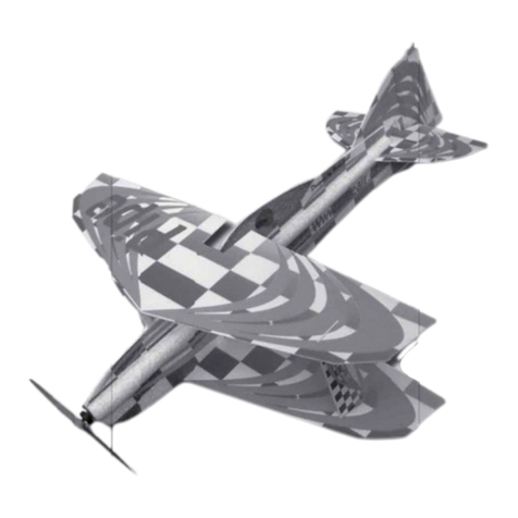
Jerry
Dear customer, congratulations on the purchase of the Jerry model. To enjoy building and
flying the model most, please read carefully the building instructions before you begin and
make sure that you understand the building process. With any question please contact your
dealer or the manufacturer.
DESCRIPTION OF THE MODEL:
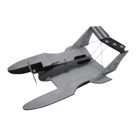
The model is a flying wing completely made of the EPP, and it is intended to fly for fun. Its
weight starting at a mere 100 grams makes it an ideal model for flying in virtually any place
(e.g. a school ground, or in the street). It is slated not only for experienced pilots, but also for
slightly advanced modellers. You can power the Jerry with a motor from our production, such as
the HCS C-40W/2, and 2 LiPol cells. Thanks to the well thought-out design the building should
take about 40 minutes. It is also possible to use the GWS 40 fan.
BUILDING PROCESS:
Unless otherwise stated, all parts are to be glued with the cyanoacrylate (CyA) glue. Start the
building of the model by gluing both wing halves together (Fig. 1). According to Fig. 2, glue
the cockpit enclosure in its rear part onto the wing, then bend the enclosure and glue it at the
front edge (Fig. 3). Using a sharp knife, cut a 6 mm-deep slit in each wing half and push into
it the cables of the elevon servos.(Fig. 4). Push the servos into the prepared openings (Figs.
5 and 6) and secure the servos in place using screws or cyanoacrylate glue. If the opening for
servos would be smaller than necessary, cut away the excess foam with a knife or a hot wire
in a solder gun. Glue the elevon horns in place (Fig. 7) and install the control rods (Fig. 8).
The control rods have to be of equal length (Fig. 9). Glue the servo and control rod/control
horn protectors in place (Fig. 10) and also the vertical stabilisers (tail fins, Fig. 11) The motor
could be installed using a tubular mount according to the Figs. 12, 13, 14. Another possibility
is to utilise a classical motor bearers glued inverted and secured using the remaining control
rods. (Figs. 15, 16, 17). Insert the receiver, controller and propulsive batteries into the prepared
openings (Fig. 18); the openings could be enlarged as necessary. Lead the antenna along the
wingspan (Fig. 19). This is the finishing step of the building process. Check the position of
the centre of gravity – it should be 110 mm from the nose of the model In case of necessity
balance the model using some lead.
For the initial flights, set the control surface deflection to about 50 %. The base setting of the
elevons is 9 millimetres up at the trailing edge near the wing tip, with the wing lying on a flat
even surface. The model has, thanks to its layout, a remarkably pleasant flight behaviour; it
is able to fly both very fast and very slow. Bear in mind, please, that this model is not a toy
– avoid flying in places where health and/or property of not only yourself, but of other people
as well, could be jeopardised.
Lots of fun and many happy landings wishes FreeAir.
Proven powerplant/propeller combinations::
HCS C 40W/2 4,5/4 propeller 3x Lipol 360mAh mass 115 g
(very fast, adrenaline flying)
HCS C 40W/2 4,5/4 propeller 2x Lipol 600mAh mass 125 g (easy, fun flying )
HCS C 40W/3 4,5/4 propeller 3x Lipol 600mAh mass 125 g (long fun-flying flights)
HCS C 30W/2 4,5/4 propeller 2x Lipol 360mAh mass 95 g (indoor flying)
PARTS LIST
Part name Pcs Part name Pcs
Wing half of EPP 2 Vertical fin of EPP 2
Fuselage of EPP 1 Elevon control rod 2
Instructions 1 Elevon horn 2
Elevon protector 2
You will need the following tools and materials:
CyA glue, CyA glue accelerator, a sharp (modelling) knife. To complete the model you need
the following: a receiver (MZK), two servos (Waypoint W-038), a controller (TMM 0710-3 or
Jeti 04), a battery pack (2-3 LiPol cells of 340 -600 mAh), a motor (HCS C-40W/2 or similar
of about 40 W power output).
2
Jerry www.freeair.cz

