Micro BLADE
Dear customer, congratulations on the purchase of the MicroBlade model. Before you
begin, please read carefully the building instructions and make sure that you understand the
building process.
DESCRIPTION OF THE MODEL:
The MicroBlade model was designed from the outset to use the expanded polypropylene
(EPP) as its main building material, with some carbon composite components. Thanks to its
low weight, beginning at only 120 grams, it is an ideal model for the indoor flying, but also
perfectly suitable for flying outdoors in calm weather. We suggest you to use our HCS C 40w/2
motor (fed from 2 cells of LiPol batteries of 340 mAh capacity). Thanks to the well thought-out
design, the actual assembly of the kit parts that fit together as an easy jigsaw puzzle would
take only 90 minutes of building time. All openings and compartments for the RC equipment
are ready made. The final colour finishing could be done using the simplest spray guns with
colours for textile, or you could order the model in a colour scheme. Your fantasy is not limit
– only the model’s weight watching is.
BUILDING PROCESS:
Start with gluing both wing halves to the fuselage centre section, as shown on fig.1,
using either the standard CA glue or the five-minute epoxy. According to fig.1 and 2, and using
a sharp modelling knife or a slot milling cutter, cut a 1.5 mm deep spanwise groove at the
distance of 50 mm from the wing leading edge. Then insert and glue the 1 mm thick carbon
wire to both surfaces of the wing halves, (fig. 3), and secure the joint with the CA glue. Each
aileron is a part of the wing half, do not cut it away. Now using the carbon tube as a core
drill, open up the hole in the elevator (fig. 4) at a point 6 mm from its skewed edge. Slip the
elevator control arm in place (fig. 5, 6) and then glue the whole assembly with its bushings
(fig. 7) into the fuselage (fig. 8). Put the model on its back and glue on the bottom half (the
vertical web, fig. 9) of the silhouette fuselage. Cover the servos with the paper masking tape
and glue them to the fuselage (fig. 10).
If you use other types of servos than the recommended ones, enlarge the servo cutouts,
keeping them, however, slightly smaller than the overall dimensions of the servos, so that they
would push-fit into their respective cut-outs.
I install aileron servo (CA glue) in the fuselage (fig. 11).
Glue the undercarriage slot reinforcing doublers to the fuselage, as shown on fig. 12.
According to the fig. 13, glue the aileron control horns and install the push-pull rods (figs.
14, 15). Connect the rod to the elevator horn. (fig. 16). Glue the top fuselage web (spine) in
place (fig. 17). Open-up the slot for the rudder hinges and glue in the rudder (fig. 18). Glue the
rudder control horn in place and, in a way similar to the way the elevator control push pull-rod
was installed, install the rudder push-pull rod (fig. 19).
Glue the motor bulkhead (fig. 20), ensuring the correct side- and downthrust (3° to 5°
to right and 0° down). Glue in the acarbon wire fuselage reinforcement (fig. 21).
Install the motor and screw on the motor bulkhead as shown in (fig. 22).
According to the (fig. 23), assemble the undercarriage. Starting on one side and using a
1mm bit, drill a hole for the 10mm carbon.. Secure the bolt from both sides of the leaf spring
with CA. Put on wheel and secure it with blob CA, pay attention not to glued wheel.
Having this done on one side only, slide the leaf spring though the fuselage slot, not
gluing it at the time (fig. 24). Then install the second undercarriage wheel, and stand the
model on the undercarriage.
Check that the wing is parallel to the ground (the model stays square, fig. 25) and glue
the undercarriage to the fuselage.
Check the elevator servo is in neutral position and glue the elevator and rudder (fig.26 )
in place. According to (fig. 27), connect the controller to the radio receiver and solder its power
cables to the motor.
Attach the propeller to the shaft by a CA glue or a worm.
Check the position of the centre of gravity (CG) and, based on its established position.
Fine-balance the model using the power battery pack (fig. 29), attached either by a
pieces of the velcro strip, or by opening up a compartment in the fuselage spine, inserting the
battery there. Ensure that the opening is some 1 to 2 mm narrower than the battery pack to
provide for its tight fit. The required position of the centre of gravity is 65 mm from the wing
leading edge to the rear, as shown on the (fig. 28).
This is the last step of building the model. Set the maximum throw of the control surfaces,
utilising the exponential functions of the RC set if wanted and available. Take into consideration
your own piloting skills.
This model is no toy – therefore avoid flying in crowded places or such areas where health
or property not only of yourselves, but also of third persons could be jeopardised.
A lot of fun and many smooth landings with your model wishes FreeAir.
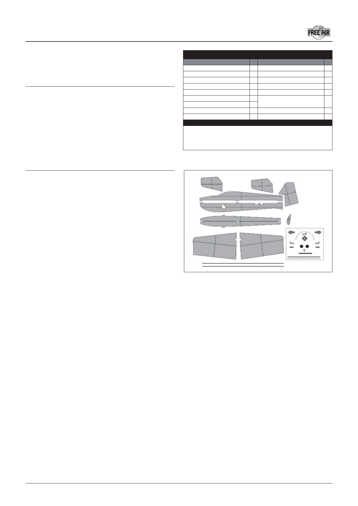
PARTS LIST
Part name Pcs Part name Pcs
Fuselage part of EPP 3 Push-pull rod horns 3
Elevator and rudder control rod 2 Carbon wing spars (500 x 1 mm) 2
Wing of EPP 2 Elevator joiner of carbon (4x100 mm) 1
Elevator and rudder of EPP 3 Instructions 1
Undercarriage slot doubler 2 Fuselage reinforcing carbon (1x5 mm) 2
Aileron push-pull rod 2 Slab elevator set
(bushings and control lever) 1
Plastic hinge 2
Undercarriage carbon leaf spring 1 Undercarriage wheel 2
Motor bulkhead 1 Wheel pant of EPP 2
You will need the following tools and materials:
CA glue, CA glue activator, sharp (modelling) knife, 150 mm extension cable for servo. To
complete the model you will need: a receiver (MZK), servos (Wipont W-060), a controller
(TMM-1210-3 or Jeti 12), an accumulator battery (3s2p LiPol cells of 640-1200 mAh),
a motor (HCS-150/3E or similar of about 150 W output).
2
Micro BLADE www.freeair.cz


