2MICROBAT www.freeair.cz
MICROBAT
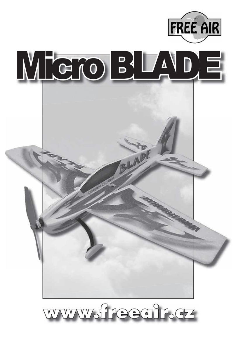
Dear customer, congratulations on the purchase of the Microbat model. To enjoy building and
flying the model most, please, read carefully the building instructions before you begin and
make sure that you understand the building process.
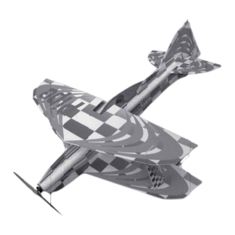
DESCRIPTION OF THE MODEL:
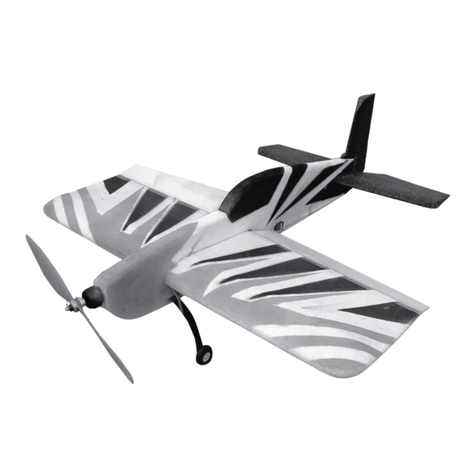
The Microbat model was designed from the outset for expert pilots. It can execute the full
range of aerobatic figures and it is ideal also for training of the new aerobatic manoeuvres and
stunts that for the time being you would be afraid to attempt with a large aerobatic aeroplane.
The complete model is made of the Expanded Polypropylene (EPP) and it is reinforced with the
carbon fibre composite elements. Its elevator is of the all-flying (slab) layout, both its surfaces
(port and starboard) are joined and supported by a carbon composite tube. The undercarriage
consists of the foam-rubber wheels attached to the carbon-fibre composite undercarriage leaf
spring, with the tail skid. To control the model, four HS-55 or similar servos are utilised. We
suggest that you use a Rotex AC motor or other mark of similar power, fed from 2 or 3 cells of
LiPol batteries.
BUILDING:
All parts gluded using a CyA glue. Start with assembling the wing. Glue the carbon
composite main spars, as shown on figs.1 and 2, using the CyA glue. Using a sharp knife, cut
in the spar web a spanwise groove (slit) some 3 mm deep, and insert the carbon reinforcement
into it. Then glue the slit together again. Now glue together the main spar and the trailing
section of the wing, using the five-minute epoxy. Once the epoxy cures, glue together the wing
halves (fig. 3) and join them with the carbon composite rod. Ensure that the wing has no (0°)
dihedral. The figs. 4 and 5 show the way of attaching the ailerons, using the glass-reinforced
self adhesive tape, sprayed with the 3M contact glue. After some 15 minutes, improve the
adhesion of the tape by ironing it on with the smoothing iron heated to 60°C. Cut out the
openings for the aileron servos, using a sharp knife; cut them slightly smaller than the servo
dimensions so that the servos fit very tightly in them (push-fit)(fig. 6). Cover the servos with
the paper masking tape and (according to fig. 7), glue in place, using the CyA glue. As shown
on figs. 8 , attach the aileron horns, using the five-minute epoxy glue, and install the push-pull
rods, finishing thus the major portion of work on the wing.
Now start working on the fuselage. From the inner fuselage sections, cut away the parts
that would be glued into the fuselage upper parts (figs. 9, 10,11 and 12). Using a sandpaper,
round the fuselage upper contour at the glued joint of outer and inner sections to a smooth
shape. Now, according to the fig. 13, glue together the upper fuselage and the wing, using
the five-minute epoxy; check before the glue cures that the parts are symmetric and at right
angles. In one third of the elevator chord, drill the hole for the elevator joiner tube, using
the same tube as the core drill (fig. 14). Glue together (CyA) the slab elevator control lever
(horn), consisting of 3 parts, as shown on figs. 15, ensuring that the assembly is true and at
right angles to the fuselage. Cut in the fuselage, 70 millimetres from the fuselage end, the
semicircular groove for the elevator pivot and control lever assembly and glue with CyA the
doublers to the elevator control horn (fig. 16 and 17). Ensure that the groove is at right angles
to the vertical longitudinal plane of the fuselage and that no glue comes into the sliding
surfaces and bushings, rendering the control circuit inoperative.
Using the fig. 18 as a guide, cut from the lower inner fuselage section the servo bulkheads
and the pillars supporting the elevator push-pull rod guides. Place the servo between the
bulkheads and install the elevator control rod (see figs. 19 and 20). Connect the servos (fig.
21) and the controller (fig. 22) to the receiver. Check that the deflections of the control
surfaces are equalised; if not, adjust the control rods.
In the lower fuselage, at a distance of about 42 mm from the fuselage rear end, cut out
the compartment for the rudder servo (figs. 23). Now, using the five-minute epoxy, glue the
undercarriage base slab to the fuselage bottom (figs. 24). The undercarriage base slab lies
near the wing cutout.
Using a modelling knife, open up the slot for the undercarriage leg above its base; slide
the undercarriage leaf spring through the slot (figs. 25 and 26). Glue the undercarriage in
place with the five-minute epoxy. Using a two-millimetre drill, open up in the undercarriage leaf
spring the holes for the wheel bolts, doubling as axles. Slide the wheels onto their respective
axles and secure them with the nuts (fig. 27). Glue (CyA) the elevator in place (figs. 28 and
29), checking the geometry (squareness, symmetry and being parallel to the wings) of the
empennage. Connect the rudder servo to the receiver and close off the fuselage bottom (figs. 30
and 31). Join and glue with CyA the rear fuselage together, as shown on fig. 32 and 33. Attach
the rudder, using plastic hinges( fig.34) . Install the motor mount with screws to the motor
bulkhead (fig. 35 and 36) and secure the motor. Solder the motor power leads to the controller
and according to figs. 37 and 38, glue the motor bulkhead to the fuselage with the CyA.
The model‘s centre of gravity (C of G, CG) has to be 115 ±15 mm from the wing root
leading edge (fig. 39), and it can be adjusted by choosing the correct position of the battery
(fig. 40). The battery compartment overall dimensions should be made some 2 to 3 millimetres
smaller to ensure the battery a tight fit. If you have a piece of blue covering foil, you could
simulate the cockpit canopy with it, or spray the same in some appropriate colour (blue, black
etc.).
Now you have the built model and only few things to finish. Adjust the deflection of the
control surfaces to 45 degrees maximum. If you have not flown with the all flying (slab)
elevator and rudder yet, reduce for the first training period their throw to ± 20 mm.
Check the elevator is trimmed to zero incidence and off you can go. For the advanced
flying you may use the ailerons as flaperons, mixing them with the elevator inputs.
A lot of fun and many smooth landings with your Microbat model wishes FreeAir.
PARTS LIST
Part name Pcs Part name pcs
Fuselage of EPP 1 Push-pull rod levers 3
Elevator and rudder control rod 2 Wing main spars of carbon composite
(1 x 330 mm) 1
Wing of EPP 1 Elevator joiner of carbon (5x100 mm) 1
Elevator and rudder of EPP 3 Slab elevator set (bushings and control
lever) 1
Aileron of EPP 2 Motor bulkhead 1
Wing joiner tube of carbon composite of
1 x 100 mm 1 Undercarriage wheel 2
Aileron push-pull rod 2 Set of bolts 2
Plastic hinge 2 Set of nuts 4
Tail skid of EPP 1 Undercarriage leaf spring of carbon
composite 1
Plastic tube (3x10 mm) 4 Undercarriage base 1
Instructions 1
You will need the following tools and materials
CyA glue, CyA glue accelerator, five-minute epoxy, polyurethane (PU) glue, 2 mm dia drill
bit, glass-weave-reinforced self-adhesive band, sharp (modelling) knife, sandpaper, 3M
contact glue in a spray can, soldering pistol. To complete the model you need the following:
Receiver (Rex 5+), servos (HS-55), controller (TMM 1210-3), battery pack (2-3 LiPol cells of
720-1500 mAh), motor (Rotex 27/6/17), propeller.
