manuals.online logo
Brands
  1. Home
  2. •
  3. Brands
  4. •
  5. FREE AIR
  6. •
  7. Toy
  8. •
  9. FREE AIR Jak 55 User manual

FREE AIR Jak 55 User manual

Jak 55
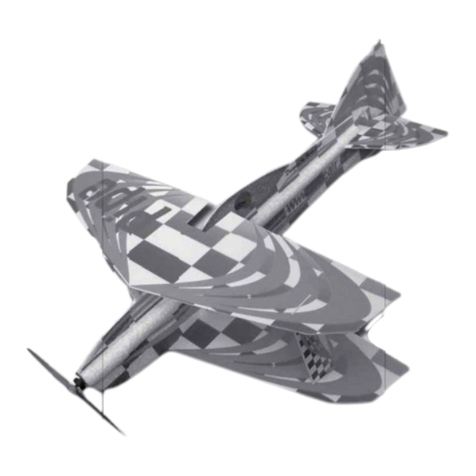
Gratulujeme! Stali jste se šťastnými majiteli špičkového 3D akrobatického modelu Jak 55 vyrobeného z EPP metodou
prostorového trupu. Tato technologie – podobná stavběpapírového modelu zaručuje vysokou pevnost a dobré letové vlastnosti při
zachování nízké letové hmotnosti důležité pro létání 3D akrobacie.
Obsah stavebnice
Název počet Název počet
Trup z EPP 1 Stojina křídla (1x1000mm) 2
Páteřz EPP 1 Kola 35mm 2
Křídla z EPP 2 Táhla - Al drat 1,6mm 4
Výškové kormidlo z EPP 1 Ostruha Al drat 1,6mm 1
Směrové kormidlo z EPP 2 Podvozek uhlík 1
CNC-frézovaná sada příslušenství 2 Osy kol M2x20 2
Přepážky z EPP 4 MatičkyM2 4
Lože podvozku z EPP 1 EPP destička 1
Kabina plexi 1
Dráty uchycení kabiny 2 Stavební návod 1
Motorová přepážka překližka 1
Ke stavběbudete potřebovat.: vteřinové CA lepidlo, urychlovačCA lepidla, skalpel, pravítko, brusnou mřížku na sádru
RC vybavení: 4ks serva 6g (Waypoint 060), 4 ks prodlužovacích kabelů, přijímač5 kanál (MZK Penta), AC regulátor 12-25A,
AC motor 100-200W (HCS 150W), vrtule (GWS) 10/6, 11/4.
Stavba: Veškeré spoje lepíme pomocí řídkého vteřinového lepidla. V první fázi spoje jen pojistíme tak, aby držely u sebe a
následněpo kontrole pozice a souměrnosti je zalepíme. Dáváme při tom pozor na to, aby lepidlo neproteklo skrz EPP a
nepřilepili jsme si prsty ke konstrukci.
Křídla: Křídla slepíme v ose profilu k páteři trupu.Obr 1. Z přiložené destičky EPP vyřízneme stojinu na spodní i horní stranu
páteře a přilepíme.Obr 2,3,4,5. Na horní i spodní straněkřídla v místěstojiny zařízneme drážku pro uhlík 1mm. Uhlík do drážky
zatlačíme zkontrolujeme rovinu a zalepíme.Obr 6,7,8,9
Trup: Do páteře zalepíme přepážky a pomocnou tvarovou výztuhu podvozku.Obr 10,11,12. Na trupu zalepíme přední spodní
tvarový výstřih.Obr13. Trup stočíme, zajistíme páskou a necháme alespoň30 min přetvarovat. Obr14,15. Vtrupu jsou
předfrézovaná zahloubení pro zámečky páteře. Z nich odstraníme přebytečné EPP tak abychom nepoškodili vnější povrch trupu.
Obr16,17. Trup rozřízneme od náběžné hrany křídla k bočnímu tvarovému výstřihu.Obr 18,19. Trup navlékneme na páteř,
nasadíme na zámečky páteře a pomocí např. špendlíkůzafixujeme.Obr 20. Bodověpřilepíme k páteři. Tato operace je na celé
stavběnejnáročnější. Musíme kontrolovat zda není trup ohnutý nebo překroucený. V případěchyby lepené body odřízneme a
chybu odstraníme. Teprve poté páteřpřilepíme po celé délce.Obr 21,22. V přední části přilepíme trup ke křídlům a slepíme
rozříznuté boky. Obr 23. Přilepíme spodní část přední přepážky. Přepážky podvozku prozatím nelepíme. Poté slepíme přední
horní část trupu a zbylé tvarové výstřihy.Obr24,25. Přilepíme horní část přední přepážky. Na závěr slepíme zadní horní část trupu
od kabiny ke směrovce.Obr 26. Konce bočnic stlačíme k soběa slepíme.
Kormidla: Do zářezu zasuneme výškovku, zkontrolujeme souosost s křídlem a přilepíme. Na horní části trupu pod
stabilizátorem směrovky obroušením vytvoříme plošku pro přilepení stabilizátoru směrovky a stabilizátor přilepíme.Obr 27,28.
Pohyblivá část směrovky je zavěšena na skleněných pantech (6ks) z nichž jeden tvoří páku . Osou je Al drát 1,6mm protažený
skrz panty a zapíchnutý do směrovky.Obr 29,30,31,32. Panty zařízneme, vyzkoušíme pohyblivost a zalepíme.Obr 33,34.
Výchylky kormidel můžeme ještěupravit zvětšením výřezůve směrovce i výškovce. Obr35.
Osazení serv: Pro dosažení potřebných výchylek kormidel i křidélek použijeme prodlužovaní páky na serva. Ty navlékneme na
stávající páku serva a zalepíme. Obr36. Prodloužíme přívodní kabely. V křídlech vyřežeme otvory a do nich zatlačíme
serva.Obr37. Kabely s prodlužováky zařízneme do křídla.Obr38. Protáhneme do trupu v místěkabiny Obr 39. Do křidélka
zařízneme páky a spojíme se servy táhlem pomocí „Z“ohybu (Al drát 1,6 mm).Obr40. Do bočnic před náběžnou hranou výškovky
vyřízneme otvory a do nich zasuneme serva kormidel. Obr41 Do výškovky zařízneme a zalepíme skleněnou páku. Serva spojíme
s pákami táhlem (Al drát 1,6mm). Zapojíme a vyzkoušíme. Serva zalepíme. Obr42
Podvozek: V podvozku vyvrtáme dírky pro osičky kol (šroub M2). Kola přišroubujeme Obr43. Trup v místězesílení mezi
přepážkami podvozku vyřízneme. Vsadíme, seřídíme a přilepíme podvozek i přepážky. Obr44. Překryjeme vyříznutým kusem a
ten také přilepíme.Obr45 Pod kormidla zalepíme ostruhu z drátu.Obr46,47.
Motor: Motor s připojeným regulátorem přišroubujeme do motorové přepážky, bez vrtule vyzkoušíme směr otáčení a přepážku
zasuneme a lehce přilepíme do trupu. Obr 48. Vyosení motoru by mělo být 2-4 stupnědoprava dle použité vrtule. Vyosení je
třeba doladit až při zalétání (zavisení).
Kabina: Kabinu vystřihneme tak aby na ní zůstal lem cca 1cm. Samolepící páskou – nejlépe modré barvy ji olemujeme a
vyznačíme přepážky. Kabinu připasujeme na trup a z jednoho boku v lemu kabiny uděláme dvědíry 1,6mm. Skrz tyto otvory do
bočnice zabodneme dva Al dráty které propíchneme na druhou stranu trupu. Místa výstupu drátůsi označíme na druhém lemu
kabiny. Dle označení vyvrtáme díry 1,6mm.Obr49. Dráty do bočnic zalepíme a tím zpevníme bočnice v místěkabiny.
Baterie: Bateriemi měníme těžištěmodelu. Na páteřv přední části nalepíme pruh suchého zipu(chlupy). Na baterie nalepíme
protikus suchého zipu (háčky). Baterie vkládáme kabinou. Při zalétání můžeme posunem baterií najít ideální těžištěpro náš styl
létání.
Těžiště: těžištěje 90mm od náběžné hrany křídla.
Zalétání: Při zalétávání postupujeme jako u jiného akrobatického modelu.
Mnoho šťastných visení, harrierů, nožových letůa jiných skopičin přeje Free Air
Manual Jak55 www.freeair.cz Page nr..: 1 / 1
Jak 55
Congratulations!
You have become a happy owner of a top-rated 3D-flying model of the Yak-55 aerobatic special. It
is made of expanded polypropylene (EPP), using the semi-monocoque fuselage structure. This
construction method, similar to building a real aeroplane or a paper model, ensures high strength
and good flying characteristics while keeping the weight low – a paramount feature for flying the
3D aerobatics. Contents of the kit
Item Pieces Item Pieces
Fuselage of EPP 1 Wing spar flange rod
(1x1000 mm) 2
Spine of EPP 1 Wheels, 35mm 2
Wings of EPP 2 Z-shaped control rods - Al
wire of 1,6 mm diameter,
60 and 120 mm long
2+2
Horizontal tail of EPP 1 Tailskid – a 80x50 mm V-
shape, bent of Al wire of 1,6
mm diameter,
1
Vertical tail of EPP 2 Carbon undercarriage leaf 1
CNC-milled set of accessories 1 Wheel axles M2x20 2
Bulkheads of EPP 4 Nuts M2 4
Undercarriage support of EPP 1 EPP plate of 100x50 mm 1
Cockpit canopy (clear plastic ) 1 Rudder post of Al wire, 1,6
mm diameter, 190 mm long 1
Canopy holding wires of Al, 1,6
mm diameter, 120 mm long 2 Building instructions 1
Motor bulkhead of plywood 1
To build the model, you need the following: CA glue, CA glue accelerator, balsa knife or similar
sharp cutter, a ruler/straightedge (preferably steel), abrasive (sanding) mesh for plasterboard
hand finishing.
RC equipment: four 6g servos (Waypoint 060), 4 split cables for servos, five-channel receiver
(MZK Penta), AC controller 12-25A, AC motor of 100-200W (HCS 150W), propeller 10/6 or 11/4
(GWS).
Building process: Glue all joints with thin CA glue. In the first phase tack-glue the joints so that
the parts just hold together, then check their relative positions and symmetry as needed and finally
glue them thoroughly. Ensure that the glue would not penetrate through the EPP and glue your
fingers to the structure.
Wings: Glue (butt-joint) the wings with the fuselage’s horizontal spine, their chord parallel and
centric, Fig. 1. Cut the upper and lower vertical web stiffeners from the accessory EPP plate and
glue to the spine, Figs. 2, 3, 4 and 5. Cut a spanwise, 1,5-2 mm deep slit into the upper and lower
surface of the wing for the wing spar flange of carbon rod of 1 mm diameter. Push the rods into
their respective slits, check the straightness of the rods/wings and glue the rods in place, Figs. 6,
7, 8 and 9.
Fuselage: Glue the bulkheads and the auxiliary former/support of the undercarriage, Figs. 10, 11
and 12. Glue to the fuselage the lower front fairing, Fig. 13. Roll the fuselage, secure (bind) with
tape and leave a minimum of 30 minutes to get the shape, Figs. 14 and 15. There are slots milled
into the fuselage for the spine tongues. Remove the excess EPP so that the outer surface of the
fuselage shell would not suffer any damage, Figs. 16 and 17. Cut the fuselage from the wing
leading edge to the side transition fairing Figs. 18 and 19. Slide the fuselage onto the spine, make
the tongues fit into the notches in the fuselage shell and, using e.g. pins, fix them in place, as per
Fig. 20.
Manual Jak55 www.freeair.cz Page nr..: 1 / 9
Picture
Tack-glue the fuselage outer shell to the tongue. This building step is the most demanding one of
the complete construction process. Check that the fuselage is not bent, twisted or otherwise
distorted. In case of the faulty alignment cut the glued spots and rectify the assembly. Only then
glue the spine along the full length of fuselage, Figs. 21 and 22. In the front, glue the fuselage to
wings and glue the cut sides together, Fig. 23. Glue the section of the front bulkhead in place. Do
not glue the undercarriage bulkhead at the moment. Then glue the front upper section of fuselage
and the remaining fairings, Figs. 24 and 25. Glue the upper part of the front bulkhead. Finally, glue
together the rear upper fuselage, from the canopy to the vertical tail, Fig. 26. Push the side walls
together and glue in place.
Control surfaces: Insert the horizontal tail into its slit, check that it is parallel to the wing and glue
in place. Sand the fuselage top beneath the vertical stabilizer to make the mating flat surface and
glue the stabilizer to it, Figs. 27 and 28. The rudder is attached to the fin by glassfibre hinges (6
pieces), one of them doubles as the rudder horn. The rudder shaft consists of 1,6 mm thick Al
wire, inserted through the hinges and pushed into the rudder, Figs. 29, 30, 31 and 32. Cut the
slits, insert the hinges into them, check the freedom of hinge movement and glue the hinges in
place, as per Figs. 33 and 34. The range of elevator and rudder deflection could be increased by
enlarging the cut-outs in the rudder and elevator, Fig. 35.
Installing servos: To get the required deflections of the elevator, rudder and ailerons, use the
servo arm extenders. Slide the extenders on the existing servo arms and glue in place, Fig. 36.
Split (extend) the servo cables. Cut openings in the wings and push the servos into them, Fig. 37.
Slit the wing and insert the cables with extenders into the slits, as per Fig. 38. Thread the cables
into the fuselage at the cockpit Fig. 39. Make slits in the ailerons, insert and glue the control horns
into them. Connect with servos by control rods with “Z“ bend (Al wire of 1,6 mm diameter), as per
Fig. 40. Cut openings into the fuselage sides in front of the horizontal stabilizer and insert elevator
and rudder servos, Fig. 41. Slit and insert the glassfibre control horn into the elevator. Connect the
servos with the horns by a control rods (Al wire of 1,6 mm diameter). Connect and test. Glue
servos, Fig. 42.
Undercarriage: Drill holes for the wheel axles (M2 bolts). Bolt the wheels in place, Fig. 43. Cut
the fuselage at the doubler between the undercarriage bulkheads. Insert, adjust and glue the
undercarriage and bulkheads in place, Fig. 44. Cover with the cut-out piece and glue in place, as
per Fig. 45. Glue the tailskid, made-up from the wire, Fig. 46, 47.
Motor: Screw the motor (with controller connected) to the motor bulkhead, check the sense of
rotation of the motor without the propeller; insert and tack-glue the bulkhead into the fuselage, Fig.
48. The motor axis should be offset by some 2-4 degrees right according to the propeller used.
The offset has to be adjusted according to test flying (during hovering flight).
Canopy: Cut the canopy so that a rim/flange of about 10mm would remain. Using a self-adhesive
tape, preferably blue, make the framing and mark the bulkheads. Fit the canopy to the fuselage
and make two 1,6 mm holes through the flange on one side of the canopy. Push two Al wires
through these holes into the fuselage side wall, across it and out on the other side. Mark the exit
holes for the wires on the other side of the canopy flange. Drill the 1,6mm holes in the marked
locations as per Fig. 49. Glue the wires to the fuselage sides, stiffening the side walls at the
canopy/cockpit cut-out.
Battery: The battery pack serves to adjust the centre of gravity (CG). Glue/attach a piece of
Velcro strip (hair/loop) to the front of the spine. Fit the opposite part (hooks) of the Velcro strip to
the battery pack. Insert the battery pack through the cockpit. During the test flying the ideal
position of the centre of gravity for the individual style of flying could be found by varying the
position of the battery pack.
Centre of gravity: The centre of gravity is 90 mm to the rear of wing leading edge.
Test flying: Test flying should be carried out the same way like with any other aerobatic model.
Many happy hovers, harriers, knife-edges and other stunts wishes Free Air
Manual Jak55 www.freeair.cz Page Nr..: 2 / 9
Picture
01 02
03 04
05 06
07 08
Manual Jak55 www.freeair.cz Page Nr..: 3 / 9
Picture
09 10
11 12
13 14
15 16
Manual Jak55 www.freeair.cz Page Nr..: 4 / 9
Picture
17 18
19 20
21 22
23 24
Manual Jak55 www.freeair.cz Page Nr..: 5 / 9
Picture
25 26
27 28
29 30
31 32
Manual Jak55 www.freeair.cz Page Nr..: 6 / 9
Picture
33 34
35 36
37 38
39 40
Manual Jak55 www.freeair.cz Page Nr..: 7 / 9
Picture
41 42
43 44
45 46
47 48
Manual Jak55 www.freeair.cz Page Nr..: 8 / 9
Picture
49 50
.
Manual Jak55 www.freeair.cz Page Nr..: 9 / 9

Other FREE AIR Toy manuals

FREE AIR Extra 3D Adrenaline User manual

FREE AIR

FREE AIR Extra 3D Adrenaline User manual

FREE AIR BLADE User manual

FREE AIR

FREE AIR BLADE User manual

FREE AIR Micro WWII B-25 Mitchell User manual

FREE AIR

FREE AIR Micro WWII B-25 Mitchell User manual

FREE AIR the PIPE User manual

FREE AIR

FREE AIR the PIPE User manual

FREE AIR P51D User manual

FREE AIR

FREE AIR P51D User manual

FREE AIR Micro Blade User manual

FREE AIR

FREE AIR Micro Blade User manual

FREE AIR Jerry User manual

FREE AIR

FREE AIR Jerry User manual

FREE AIR Falcon F-16 User manual

FREE AIR

FREE AIR Falcon F-16 User manual

FREE AIR BLAST User manual

FREE AIR

FREE AIR BLAST User manual

FREE AIR DagoRed User manual

FREE AIR

FREE AIR DagoRed User manual

FREE AIR Mig-29 Fulcrum User manual

FREE AIR

FREE AIR Mig-29 Fulcrum User manual

FREE AIR SE 5 User manual

FREE AIR

FREE AIR SE 5 User manual

FREE AIR Mig-21 Instruction Manual

FREE AIR

FREE AIR Mig-21 Instruction Manual

FREE AIR F-15 Eagle User manual

FREE AIR

FREE AIR F-15 Eagle User manual

FREE AIR MicroBlade User manual

FREE AIR

FREE AIR MicroBlade User manual

FREE AIR L-159 Alca Quick start guide

FREE AIR

FREE AIR L-159 Alca Quick start guide

FREE AIR Micro WWII B-25 Mitchell User manual

FREE AIR

FREE AIR Micro WWII B-25 Mitchell User manual

FREE AIR BLITZ User manual

FREE AIR

FREE AIR BLITZ User manual

FREE AIR Mig-21 Instruction Manual

FREE AIR

FREE AIR Mig-21 Instruction Manual

FREE AIR Mig-29 Fulcrum User manual

FREE AIR

FREE AIR Mig-29 Fulcrum User manual

FREE AIR Jas 39 Gripen User manual

FREE AIR

FREE AIR Jas 39 Gripen User manual

FREE AIR I-16 User manual

FREE AIR

FREE AIR I-16 User manual

FREE AIR Microbat User manual

FREE AIR

FREE AIR Microbat User manual

FREE AIR Grumman F-14 Tomcat User manual

FREE AIR

FREE AIR Grumman F-14 Tomcat User manual

Popular Toy manuals by other brands

Troy Built Models Stinson 108 instruction manual

Troy Built Models

Troy Built Models Stinson 108 instruction manual

Faller 180564 quick start guide

Faller

Faller 180564 quick start guide

Accucraft Dora instruction manual

Accucraft

Accucraft Dora instruction manual

VQ VQAO41G instruction manual

VQ

VQ VQAO41G instruction manual

Esu Rivarossi BR 58 manual

Esu

Esu Rivarossi BR 58 manual

LEGO DISNEY PRINCESS 41054 Assembly information

LEGO

LEGO DISNEY PRINCESS 41054 Assembly information

Eduard Fw-190D-9 exterior set manual

Eduard

Eduard Fw-190D-9 exterior set manual

marklin 29309 manual

marklin

marklin 29309 manual

The World Models Manufacturing Sky Link EP instruction manual

The World Models Manufacturing

The World Models Manufacturing Sky Link EP instruction manual

Park Pilots DHC-2 Beaver Operation manual

Park Pilots

Park Pilots DHC-2 Beaver Operation manual

Mattel DVF3 instructions

Mattel

Mattel DVF3 instructions

Joysway Offshore Lite Warrior V3 2.4GHz RTR 8206 instruction manual

Joysway

Joysway Offshore Lite Warrior V3 2.4GHz RTR 8206 instruction manual

Aria Child 5F60E99 owner's manual

Aria Child

Aria Child 5F60E99 owner's manual

TSH GAUI X2 Assembly instruction

TSH

TSH GAUI X2 Assembly instruction

Jamara AX1 Instruction

Jamara

Jamara AX1 Instruction

Sawn Craft Cherokee 24 Assembly and setup manual

Sawn Craft

Sawn Craft Cherokee 24 Assembly and setup manual

SIG RASCAL 110 EG ARF Assembly manual

SIG

SIG RASCAL 110 EG ARF Assembly manual

Fisher-Price N6022 quick start guide

Fisher-Price

Fisher-Price N6022 quick start guide

manuals.online logo
manuals.online logoBrands
  • About & Mission
  • Contact us
  • Privacy Policy
  • Terms and Conditions

Copyright 2025 Manuals.Online. All Rights Reserved.