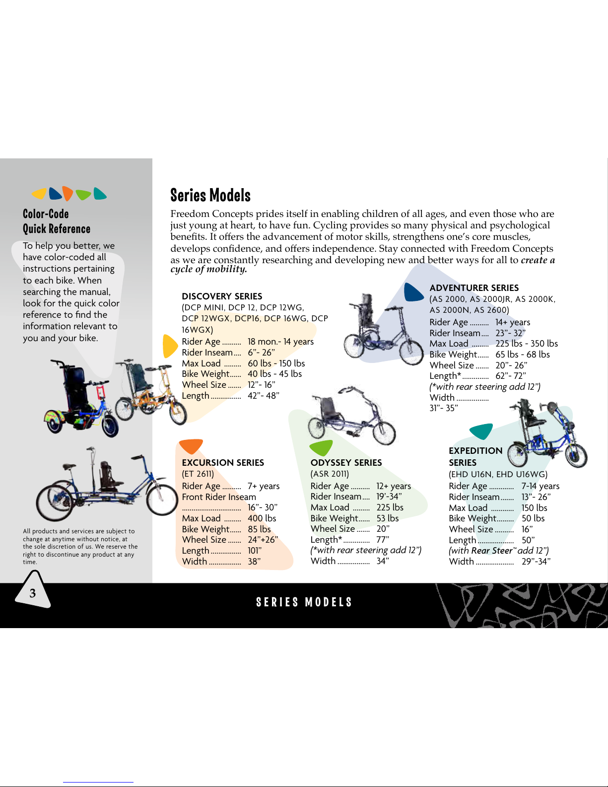
Freedom Concepts DCP MINI User manual

OWNER’S MANUAL

Model # ____________________________________________
Serial # ____________________________________________
Date of Purchase: __________________________________________
Congratulations on
the purchase of your
new Freedom Concepts
bike! This Owner’s
Manual refers to our
complete bike line and
has been color-coded
to easily reference the
options and components
that apply to your bike
needs.
We hope you enjoy your
bike for many years to
come!
Remember to always
“Cycle Hard” and
“Chill-Out” often!
WELCOME TO FREEDOM CONCEPTS
Maintenance
1. Keep tire pressure inflated to manufacturer’s
recommended pressure shown on the side of tire.
2. Keep bearings properly lubricated at all times
to ensure smooth rotation and lasting operation.
3. Make sure all bolts and screws are tight.
4. Always keep chain lubricated.
5. Always keep bike clean and dust free.
6. Keep bike out of severe weather conditions.
7. Ensure that at least 4” of seat post is in the seat
tube of frame. DO NOT raise seat post past
maximum height indicator.
8. Adjust brakes regularly to ensure proper
stopping.
9. Adjustments can be made using the
Freedom Concepts Multi-tool, which is
shipped with all orders.
Safety Considerations
Rider must be assisted at all times.
Position heels at back of foot plate
when securing straps.
Make sure belts and straps are
securely fastened.
Always wear appropriate head
protection.*Additional safety gear
recommended.
© 2013 FREEDOM CONCEPTS INC.
1
TM

2
WHERE ARE YOU GOING?
Table of Contents
Looking for something in particular? Use our handy table of contents to source out the exact
page for what you need or glance through the color-coded sections on the right-hand side for
a particular category. Please note: not all instructions are relevant to each bike. Use the quick
color-code reference from page 3 to ensure the instructions you are looking at are applicable to
your bike’s needs. Also, follow our QR Codes for online video tutorials for repairs.
Welcome ........................................ 1
• Bike Registration
• Maintenance Guidelines
• Safety Considerations
• Overview
Models .............................................. 3
• Discovery • Adventurer
• Excursion • Odyssey
• Expedition
• Color-code Reference
Straps, Harnesses
and Foot Plates ......................... 4-5
• Seat Belts and Ankle Straps
• Chest Harness
• Velcro Straps
• Toe-up Pulley Adjustments
• Foot Plate Adjustments
Seats ................................................... 6-7
• Adjusting Height
• Adjusting Incline
• T-Bar Seat Installation
• Head Support
• Swing Away Lateral Trunk
Support
• Head Rest
Steering ........................................... 8-11
• Handlebar/Grip
• Alignment
• Self-Centering Spring
• “U” Bar
• Quick Release Lever
• Handle Cable Tension
• Tandem Cable Tension
• Rear Steering Handlebar
Column.
Gear Shifting And
Crank/Sprocket
Adjustments ................................ 12-15
• Hand Grip Shifting
• Gear Box Hub
• Thumb Pedal Control Shifter
• Rear Control Gear Transfer
• Thumb/Finger Shifter
• Multi-Speed Shifter
• Rear Sprocket
• Electronic Motor
• Multi-Length Crank
• Bottom Bracket Crank
• Pedal Spacers
Braking ............................................. 15-17
• Hand Brake Tension
• Dual Cable Junction
• Parking Back Brake
• Caliper Tension
• V-Brake Tension
• Disc Brake Tension
Wheels and Tires .................... 18
• Tire & Wheel Options
• Removable Rear Wheel
Customized Options
& Accessories ............................ 19-20
• Neoprene Chest Harness
• Handcycles
• Abductor/Adduction Leg
Support
• Stationary Trainer
• Communication Tray
• Assorted Accessories
Warranty ........................................ 21
Reward Program ...................... 22
Mission ........................................... 22
Did you know?
We are so much more
than just bicycles!
Visit us online to
see all of our new
product offerings.
TM

SERIES MODELS
DISCOVERY SERIES
(DCP MINI, DCP 12, DCP 12WG,
DCP 12WGX, DCP16, DCP 16WG, DCP
16WGX)
Rider Age .......... 18 mon.- 14 years
Rider Inseam .... 6”- 26”
Max Load ......... 60 lbs - 150 lbs
Bike Weight ...... 40 lbs - 45 lbs
Wheel Size ....... 12”- 16”
Length ................ 42”- 48”
EXCURSION SERIES
(ET 2611)
Rider Age .......... 7+ years
Front Rider Inseam
............................... 16”- 30”
Max Load ......... 400 lbs
Bike Weight ...... 85 lbs
Wheel Size ....... 24”+26”
Length ................ 101”
Width ................. 38”
EXPEDITION
SERIES
(EHD U16N, EHD U16WG)
Rider Age ............. 7-14 years
Rider Inseam ....... 13”- 26”
Max Load ............ 150 lbs
Bike Weight ......... 50 lbs
Wheel Size .......... 16”
Length ................... 50”
(with Rear Steer™ add 12”)
Width .................... 29”-34”
ODYSSEY SERIES
(ASR 2011)
Rider Age .......... 12+ years
Rider Inseam .... 19’-34”
Max Load ......... 225 lbs
Bike Weight ...... 53 lbs
Wheel Size ....... 20”
Length* .............. 77”
(*with rear steering add 12”)
Width ................. 34”
Color-Code
Quick Reference
To help you better, we
have color-coded all
instructions pertaining
to each bike. When
searching the manual,
look for the quick color
reference to find the
information relevant to
you and your bike.
Series Models
Freedom Concepts prides itself in enabling children of all ages, and even those who are
just young at heart, to have fun. Cycling provides so many physical and psychological
as we are constantly researching and developing new and better ways for all to create a
cycle of mobility.
3
ADVENTURER SERIES
(AS 2000, AS 2000JR, AS 2000K,
AS 2000N, AS 2600)
Rider Age .......... 14+ years
Rider Inseam .... 23”- 32”
Max Load ......... 225 lbs - 350 lbs
Bike Weight ...... 65 lbs - 68 lbs
Wheel Size ....... 20”- 26”
Length* .............. 62”- 72”
(*with rear steering add 12”)
Width .................
31”- 35”
All products and services are subject to
change at anytime without notice, at
the sole discretion of us. We reserve the
right to discontinue any product at any
time.

K
4
STRAPS, HARNESSES AND FOOT PLATES
F
A
B
D
DJ
K
B
C
SEAT BELT &
NEOPRENE ANKLE
STRAP ADJUSTMENT
1. Loop strap as shown and
pull (A) to tighten to
desired length.
2. To close, push buckle (B)
into lock clasp (C).
3. To release, squeeze buckle
teeth (B) from side of
lock clasp (C) and pull out
buckle strap.
RIGID AND NEOPRENE
VELCRO STRAPS
Straps help keep the rider’s
feet firmly in place.
1. Velcro foot straps loop
through the ring (D).
2. Pull to tighten and then
press strap together so
Velcro can lock in place.
3. To remove foot, simply
peel apart Velcro straps.
TOE-UP PULLEY
TENSION ADJUSTMENT
The position on the toe-up
pulley rope can be easily
adjusted by simply loosening
the tension on the rope lock
(F) and shifting it’s position
up or down the rope to
the desired location. Once
determined, tighten the
tension back on the rope
lock. Then double-check the
position of feet
and make any
necessary minor
adjustments by
repeating the
process.
Straps, Harnesses and Foot Plates (Operations)
To ensure the bike rider is safely secured, please adjust the seat,
straps, and harnesses to the proper settings for the individual.
FOOT PLATE
ADJUSTMENTS
Our Neoprene foot plates
allow for quick and easy
adjustments to properly
match the individual’s hip to
foot ratio. Loosen the four
foot plate screws (J) and shift
the foot plate (K) forward or
backwards. Once the desired
position is determined, re-
tighten the screws in
place to the pedal
base.

G
H
F
Learn More With Our
How-To Videos.
Scan the QR Code
with your phone and you
will be linked to our
Ready to Ride Video Series.
STRAPS, HARNESSES AND FOOT PLATES
HANDCYCLE FOOTPLATE
HEIGHT ADJUSTMENT
Once the handpedals and seat positioning have been
determined, the footplates can be adjusted. The
footplate can be positioned vertically at any height
along the top or bottom of the vertical posts for
optimal leg support and comfort.
1. To move the footplates (A), turn the thumbscrew (B)
under each footplate counter clockwise until loose.
2. Then slide the footplate (A) up or down the post
(C1 or C2) to the desired height. Re-tighten the
thumbscrew (A).
3. To move the footplates (A) from the bottom post
(C1) to the top post (C2) you need to remove the
safety hitch pin (D). Simply pull the pin (D) straight
out in a horizontal motion away from the post.
Your safety hitch pin is provided to ensure you do
not lose the footplates should you not tighten the
thumbscrews (B) properly.
4. The frame clamp can also be
adjusted to move the footplates
forward or backwards. Two 1/2”
wrenches are required to
loosen the bottom clamp
bolts (E) for repositioning
to the desired location on
the bike.
5
A
B
DC1
C2
E
CHEST HARNESS STRAPS
Four #2 Robertson wood screws
(F) are used to secure the chest
harness to the seat back.
Always wear shoes when
riding to protect the feet.
Secure the foot first by
positioning the heel at the
back of the foot plate (G)
and then attaching the
straps (H) around the foot
until snug.

6
SEATS
I
J
G
F
AB
C
D
E
SEAT HEIGHT ADJUSTMENT
1. Open the quick release latches (A & B)
at the front and back of the seat base.
2. With the latches open you can raise or
lower the seat base (C) to your desired
position.
3. Close the quick release
latches (A & B) to clamp the
seat base
in the new
position.
SEAT INCLINE ADJUSTMENT
1. Open quick release latches (F) found
on both sides at the front of the
seat base.
2. Tilt seat to desired position (G).
3. Close quick release latches (F) on
both sides of seat to clamp seat
incline at a new
position.
SEAT BASE LOCATION ADJUSTMENT
1. Pull out seat base locking handle to release
seat position (D).
2. Slide seat forward or backward
to desired new location (E).
3. Close locking handle (D) and push seat
back to ensure locked position.
ADJUSTABLE
HEAD REST
1. Loosen thumb screws (I)
on both sides of seat.
2. Raise or lower head rest
(J) to desired setting for
proper trunk and head
heights.
3. Tighten thumb screws.
Please Note:
Seat lap belt must
always be worn with
the chest harness.
Proper use of chest,
lap, and hip belts
ensures trunk stability
and promotes safe
positioning.
Seats (Adjustments and Operations)
refer to the following pictures for an understanding of
*See page 9 for quick release lever tension adjustments.

E
F
D
AB
C
SEATS
T-BAR SEAT
INSTALLATION
If packaging requires, your
T-Bar seat may need to be
re-installed as shown.
1. T-Bar handle (D), behind
seat, slides over the post
all the way down to the
bottom. Tighten with
wedge bolt (E) beneath
using 6mm key.
2. At the same time, slide
the front seat post (F)
into the frame as shown.
Tighten quick release
clamps to secure chair
at desired height.
3. Close both levers to
clamp seat in position.
*See page 9 for quick
release lever tension
adjustments.
HEAD SUPPORT
HARDWARE
Head support must be
personally set exclusively to
each individual’s needs. See
detailed product manual for
proper hardware installation and
adjustment settings.
SEAT HEIGHT ADJUSTMENT
1. Open both quick release levers
(A & B).
2. Adjust seat position to desired
height (C).
3. Close both levers to clamp seat in position.
*See page 9 for quick release lever tension
adjustments.
7
SWING AWAY LATERAL
TRUNK SUPPORT
The red push button (G) allows the
Lateral Pad to flip out of the way
when getting on or off of the bike.
The pad is reversible on the bracket
for soft or firm support. Simply
remove pins (H) on both sides of the
pad by pulling. Switch
pad as desired and
then push in pins to
lock back in place
once again.
Firm
Soft
H
Opened lever
G
Closed lever

Steering (Adjustments and Operations)
All steering should be adjusted to individual needs.
On the following pages we have provided some
quick reference guides to help you with your steering
requirements.
SELF-CENTERING
SPRING
Periodically check the
self-centering spring to
ensure proper tension.
It is located on the
bottom of the bike
frame and connects to
the forks on the front
wheel. If the bike is not
moving in a straight
direction then the spring
should be replaced.
8
STEERING (ADJUSTMENTS AND OPERATIONS)
HAND DRIVE STEERING COLUMN POSITIONING
Easy adjustments (F) can be made on the Upright
Handcycle to determine the ideal hand pedal positioning
and to allow for ease with transferring on and off the bike.
RIDING
The ideal position for the hand pedals is more of a
personal choice. Our recommendation though, is to have
the hand pedals moved in towards the rider until there is
a slight bend at the elbow(G) when they are grasping the
hand pedal at its furthest position, away from the chest.
This is based on using a starting
point where the knees and hips are
in a horizontal plane(H) with the seat
of the bike in the lowest possible
position.
TRANSFERRING
For easier transfers on and off the
bike, the crank bracket should be
positioned as far away from the seat
as possible (I).
HAND DRIVE STEERING
ADJUSTMENT RELEASE
To swing hand pedals towards or
away from the seat you need to do
the following:
1. Hold the top steering column (J)
2. Open quick release lever (K)
3. Position top steering column to
desired position and close quick
release lever.
*For a better understanding on how
to work the quick release lever
see page 9.
J
FI
G
HK

B
A
A1
C
D
F
STEERING (ADJUSTMENTS AND OPERATIONS)
“U” BAR FRAME ADJUSTMENT*
Loosen quick release lever (F) to the unlock position
for adjustment of the “U” bar frame. Move forward
or backward to desired position. This is an excellent
way to move handlebar assembly out of the way when
transferring riders.
*Please note: In cases of extreme high tone the
quick release lever may need to be replaced with the
standard bolt and nut. Part # bolt: 4110440 Part # nut:
4130254
Quick Release
Lever Adjustments
From time-to-time you
may need to adjust the
tension on your quick
release levers.
1. Open lever (G), and
rotate lever handle (H)
clockwise to tighten, or
in the opposite direction
to loosen tension, while
holding nut with other
hand.
2. Once set, close the
lever to lock in place.
If lever handle cannot
close, loosen tension
by opening the handle
and turning counter-
clockwise to desired
setting.
G
H
HANDLEBAR/GRIP ADJUSTMENTS
1. To adjust handlebars in or out, loosen 6mm
socket head wedge bolt (A), approximately 4-5
full turns
2. Tap bolt (A) lightly with a hammer to unlock
wedge nut (A1) from within handlebar shaft.
3. Turn handlebar shaft (B) to desired position and
then tighten wedge bolt (A) until snug.
4. To adjust the grip, loosen 6mm socket head
clamp bolt (C) and raise or lower the handlebar
grip (D) to desired height.
5. Retighten clamp bolt (C).
9

Need A Little Extra Help Or
Don’t Understand Something?
Our service department is glad to help!
10
STEERING (ADJUSTMENTS AND OPERATIONS)
REAR STEER HANDLE
TENSION ADJUSTMENT
To adjust the tension or
re-install after shipping:
1. Loosen locking nut (A)
with 7/16 wrench.
2. Slide outer barrel (B) of
tie-rod towards locking
nut to release from the
ball joint, lifting up to
disconnect.
3. Turn base of tie-rod (C)
clockwise 1/2 to 1 full
turn at a time to increase
tension on steering.
4. Slide outer barrel of tie-rod
towards locking nut and
reconnect to ball joint.
5. Tighten locking nut (A).
*Disconnecting the rear steer
handle during transportation
of your bike will release
the tension on the steering
mechanism and allow the
rear handle to turn out of
the way–requiring less space
for transportation.
ADJUSTABLE
REAR STEERING
HANDLEBAR
COLUMN
Rear steering
column can be
bent to allow
for ease of
transportation
and storage.
1. Pop open quick release lever handle and pull outward
(F) to release spring lock.
2. Tilt steering column
on hinge bracket.
3. To re-attach column,
simply tip upward.
A C
A
B
F

F
Learn More With Our
How-To Videos.
Scan the QR Code
with your phone and you
will be linked to our
Ready to Ride Video Series.
STEERING (ADJUSTMENTS AND OPERATIONS)
TANDEM CONNECTED CABLE TENSION ADJUSTMENT
To adjust cable tension:
1. Loosen locking nut (D) with 14mm wrench.
2. Adjust the tension nut (E) with the same 14mm wrench. Turn the
nut clock wise to tighten and counter-clockwise to loosen cable.
3. Once desired tension is determined, tighten locking nut (D).
D
E
Locked Unlocked
LOCKED/UNLOCKED STEERING ADJUSTMENT
1. When locked, the steering mechanism is fixed in
position. Rear Steer™ required to steer bike when
steering is locked
2. When unlocked, it is fully functional.
STEERING
ALIGNMENT
Loosen 1/2” hex
head stem bolt (F)
approximately 4-5 turns,
tap lightly with hammer,
and rotate steering
column left or right to
align steering with front
wheel.
11
Handlebars
with Toe-up Pulley
See page 4 for loosing toe-up
pulley when moving handlebars
out of the way.

12
GEAR SHIFTING AND CRANK/SPROCKET ADJUSTMENTS
Gear Shifting (Adjustments and Operations)
All Freedom Concepts’ adaptive bicycles are adjustable to individual needs. Provided are
some quick reference graphics to help you with your shifting requirements.
BB: HAND GRIP / INTERNAL
GEAR BOX HUB ALIGNMENT
To align hand grip shifter with the gear
box hub adjust the following:
1. Shift hand grip shifter to gear “4” (B).
2. Check Nexus hub for alignment of
yellow markers (C).
3. If yellow markers are not in alignment,
turn the barrel adjuster (D) until both
lines are equal.
Please note: Any major repairs should
be handled by a qualified bike repair
shop.
BB
AA
E
C
D
B
A
AA: HAND GRIP SHIFTER OPERATION
Rotating the Revo-shifter (A) up towards the “-“ sign will lower the gear
for easier peddling. Rotating down towards the “+”sign will increase
tension when peddling.
Please note: When changing gears with the hand grip shifter
one must pause from pedaling. Once desired gear is selected
pedaling can recommence.
3-SPEED HAND GRIP
SHIFTER OPERATION
Rotate shifter (E) up towards the “3” to increase
tension when peddling. Rotating down towards the
“1” sign will decrease tension when peddling.
Please note: When changing gears with the
hand grip shifter one must pause from pedaling.
Once desired gear is selected, pedaling can
recommence.

A
B1
B2
B3
GEAR SHIFTING AND CRANK/SPROCKET ADJUSTMENTS
REAR CONTROL GEAR TRANSFER
If the cable starts to stretch through normal use, quick
adjustments can retighten the slack.
1. Shift to neutral position (B1).
2. Loosen lock nut (C) and turn barrel adjuster (D)
until loose slacking cable is tight.
3. Tighten lock nut (C).
13
EF
CD
G
H
THUMB PEDAL CONTROL SHIFTER
OPERATION
Tandem bikes allow the option for both
riders to pedal the bike at the same time.
When the shifter (A) on the handlebar is
closest to the rider the (B1) setting has
the front sprocket in a neutral position
and the front rider doesn’t contribute to
the propulsion of the bike. Pushing the
shifter (A) forward once to the (B2) position
engages the front sprocket at a low setting
so the front rider can contribute. Moving
the shifter (A) forward once again to the (B3)
position changes the sprocket to the high
setting for more contribution from the front
rider. Moving the shifter in reverse adjusts
the setting back to the beginning.
THUMB/FINGER GEAR
SHIFTER OPERATION
Change gears up or down
with an easy click. Using
your thumb, push shifter
lever (E) forward. With each
click you raise a gear. Using
your finger, pull shifter
lever (F) and with each click,
you lower a gear.
3-SPEED CABLE ADJUSTMENT
If the cable starts to stretch through
normal use, quick adjustments can
retighten the slack.
1. Shift to gear three.
2. Loosen lock nut (G) and turn barrel
adjuster (H) until loose slacking
cable is tight.
3. Tighten lock nut (G).

J
14
GEAR SHIFTING AND CRANK/SPROCKET ADJUSTMENTS
B
C
G
H
I
D
F
E
A
BOTTOM BRACKET AND CRANK ADJUSTMENT
1. Loosen 4 bracket bolts (D).
2. Remove roll pin (E).
3. Relocate bottom bracket (F) to appropriate desired position.
4. Lengthen or shorten chain with a chain break tool
to correct length (sold separately).
5. Tension chain by moving bottom bracket (F) forward until
there is no slack in the chain.
6. Tighten bolts (D), drill new hole in frame
for roll pin using bracket hole for a guide
and replace with new 1/8” roll pin (E).
PEDAL SPACERS
1. Stack spacers (G) between foot plate (H) and foot pedal base (I).
2. Secure from the top with supplied screws (J) once desired height
is determined through foot plate, spacers and into foot pedal
base.
MULTI-LENGTH CRANK ADAPTER
A multi-length crank adapter is used for even greater
adjustability of the range of motion.
1. Bolt adapter (B) to crank arm. Ensure locking
support (C) on adapter is facing crank arm to
secure adapter in place.
2. Attach pedal in appropriate adapter hole for
desired range of motion.
REAR SPROCKET
ADJUSTMENT
Check set screw
(A) periodically
for tightness.
Use 1/8” Hex Key
wrench.
This ensures good
propulsion of the
bike at all times.
ELECTRONIC
ASSIST MOTOR
Did you know we offer
the option of assist
motors? They are ideal
for those who take
extended bike rides or
for those who need
assistance on inclines or
when tandem riding. Ask
your rep today to learn
more.

A
C
Learn More With Our
How-To Videos.
Scan the QR Code
with your phone and you
will be linked to our
Ready to Ride Video Series.
BRAKING (ADJUSTMENTS AND OPERATIONS)
DISC BRAKE TENSION ADJUSTMENTS
1. Loosen the locknut (A) on the hand brake by turning
counterclockwise.
2. Turn the barrel adjuster (C) counterclockwise to
tighten tension or clockwise to loosen to
desired tension. Then tighten (A).
3. Adjust disc brake at wheel by turning
locknut (B) counterclockwise to
loosen.
4. Alter barrel adjuster (D) to desired
setting by turning counterclockwise
to increase brake sensitivity or clockwise
to decrease.
5. Tighten locknut (B).
GEAR SHIFTING
Braking (Adjustments and Operations)
All Freedom Concepts’ adaptive bicycles are adjustable to individual needs. Provided are
some quick reference graphics to help you with your braking requirements.
B
D
G
F
15
I
J
MULTI-SPEED SHIFTER
ADJUSTMENT
1. Turn top travel-limit
screw marked (I),
clockwise to reduce and
counterclockwise to
increase travel of chain
beyond 7th gear.
2. Turn bottom travel
limit screw, marked (J),
clockwise to increase
travel of chain
beyond
1st gear.
HAND
COASTER BRAKE
Just like the
conventional foot
coaster brake design,
stopping is created by
changing your direction
backwards (F) from
which you are peddling
(G).

16
BRAKING (ADJUSTMENTS AND OPERATIONS)
PARKING BACK BRAKE
(Not available for DCP Mini’s)
Parking brakes are available
for one or both rear wheels
on most bike models.
Parking brakes are ideal for
transporting riders on or off
the bike, by stabilizing the
bike movement. To use
the parking brake, simply
push the brake lever
down to lock and lift
up to release.
When transporting
someone on or off the
bike, always squeeze brake
handle (D) and push in pin
(E) to lock brake. This helps
to stabilize the bike. To
release brake lock, squeeze
handle (D).
BB: DUAL BRAKE CABLE
JUNCTION BLOCK
ADJUSTMENTS
1. Loosen the locknut (A) by
turning counterclockwise.
2. Turn the barrel adjuster (B)
clockwise to tighten and
counterclockwise to loosen
brake sensitivity.
Please note: When squeezing
the brake lever to apply the
brakes, the lever should not
touch the handlebar when
closed.
3. Turn locknut (A) clockwise
until tight.
Caution: Over-tightening
cable will cause brake pads to
constantly rub on wheels.
For instructions on
cable adjustments
to the calipers, follow
caliper brake tension
adjustments on page 17.
AA
AA: HAND BRAKE TENSION ADJUSTMENTS
1. Loosen the locknut (A) by turning away from
housing (B).
2. Turn the barrel adjuster (C) towards the housing to
loosen and away to tighten brake sensitivity.
Please note: when squeezing to apply the brakes,
the brake lever should not touch the handlebar.
3. Turn locknut (A) clockwise until tight.
Caution: Over-tightening
cable will cause
brake pads to
constantly rub
on wheels.
BB
A
C
B
ED
A
B
Cable to brake
Rider 2
brake control
Rider 1 brake control

A1, 2
B1, 2
BRAKING (ADJUSTMENTS AND OPERATIONS)
Always ensure
brake pads only
touch the rim
of the wheel.
Pads touching
the tire can
cause flats.
Learn More With Our
How-To Videos.
Scan the QR Code
with your phone and you
will be linked.
C1
D1
17
CALIPER BRAKE TENSION
ADJUSTMENTS
1. Loosen the locknut (A1) on the hand brake
by turning away from housing to allow for
fine tune hand brake adjustments.
2. Turn the barrel adjuster (B1)
counterclockwise to ensure brake pads
stop tire from spinning when hand brake is
squeezed and do not rub when released.
3. Loosen locknut (C1) on caliper brake.
4. Turn the barrel adjuster (D1) away from
the housing to bring pads closer to rim to
ensure brake pads stop tire from spinning
when hand brake is squeezed and do not
rub against the rim when released.
5. Tighten (A1 and C1).
V- BRAKE TENSION ADJUSTMENTS
1. Loosen the locknut (A2) on the hand
brake by turning counterclockwise.
2. Turn the barrel adjuster (C2) counter-
clockwise to ensure brake pads stop
tire from spinning when hand brake is
squeezed and do not rub when released.
Please note:
Any further cable repairs should be
handled by a qualified bike repair shop.

TIRE OPTIONS
For the best tire traction, we offer a variety of available options to fit your
individual needs. Our smooth tires are ideal for the city streets and indoor riding.
Our knobby tires work best for the rugged riders or off-road enthusiasts. Always
keep tire pressure inflated to manufacturer’s recommended pressure as shown on
the side of tire. For maintenance-free riding, we offer the option of solid tires with
the custom Freedom Concept gripper tread. The solid tires are ideal
for multi-user environments, as they never go flat.
.
18
WHEEL AND TIRE SYSTEMS
Wheels And Tire Systems
wheels and tires available to you.
TO RELEASE
THE WHEEL:
Open the quick release
handle and rotate
counterclockwise until
it is completely off the
drive shaft, and pull
wheel out.
TO REPLACE
THE WHEEL:
Insert and align wheel
hub on axle dowel pin
and insert quick release
bolt, tighten and close
handle to lock.
Removable Rear Wheel*
*Available only in
20” models.
SOLID TIRES
SMOOTH TIRES
WHEEL OPTIONS
We offer a variety of different
wheel options. Aluminum, steel
and ABS plastic.
Ask us about our different spoke
covers to protect little fingers.
KNOBBY TIRES

ABDUCTOR
/ADDUCTION
LEG SUPPORTS
Padded leg adduction
straps (A) or removable
abductor leg dividers (B) help individual
needs to maximize each bike ride. Call us
today or order online.
Customized Options
additional items and accessories for your customization needs.
These items can be ordered online
Don’t see something you need or want?
Give us a call! We pride ourselves on making your experience as
enjoyable as possible, and are constantly developing new products
and items based on our clients’ requests. The item you are looking
for might be in development right now!
NEOPRENE CHEST HARNESS
To accommodate your child’s growth,
we offer chest harnesses in a variety
of sizes (medium, large and extra
large). Check online for pricing and
stock availability. Also ask about our
overnight delivery to ensure they
never have to stop enjoying outdoor
adventures and fresh air.
CUSTOMIZED OPTIONS AND ACCESSORIES
STATIONARY TRAINER
Don’t let the weather slow down your exercise
program. Take advantage of our Indoor
Stationary Trainer and you can ride each
and every day, no matter what the
weather looks like outside.
Ask us about shipping
options to determine the
best means for delivery.
COMMUNICATION TRAY
Now non-verbal riders can carry
their assistive technology devices for
communicating with those
around them. Our handy
communication tray
can mount firmly to the
bike when used with the
handlebar system in the
locked position.
Learn More With Our
How-To Videos.
Scan the QR Code
with your phone and you
will be linked to our
Ready to Ride Video Series.
B
A
19
Racing Handcycles
Let nothing stop
the ride! Individually
tailored bikes focused
on arm strength for
propulsion. Ideal
for paraplegics,
quadriplegics or
amputees. Call us
today to learn more.
This manual suits for next models
15
Table of contents
Other Freedom Concepts Bicycle manuals