Fresh-Aire UV APCO RT User manual

APCO RT is installed in the ductwork of the central
air system to reduce odors and airborne biological
contaminants for improved indoor air quality. APCO RT
also reduces microbial growth within the air system.
IMPORTANT!
• Onlyqualifiedtechniciansshouldinstallthisproduct
• Installinaccordancewithrelevantbuildingcodes
• Readinstructionscarefullyincludingsafetywarnings
Important: some materials inside the air system (including lter media,
ex duct, wiring etc.) may not be UV light resistant. Use the optional UV
shield (part #TUV-SHIELD-LP) or cover the materials with reective tape.
WARNING
PROTECT EYES FROM UV LIGHT
TURN OFF UNIT OR DISCONNECT
BEFORE SERVICING
G
3Cut Hole In Duct Using Template
Cut hole in duct using a cutting tool
appropriate for the duct material.
Use scissors to cut out center of
paper template (pick circular or
linear). Trace cut-line onto duct
using template.
AirHandler
2ndUVLamp
2Installation Notes
APCO RT is usually installed on the supply side
duct just above the air system but can also be
installed on the return side if necessary.
The APCO RT unit should be oriented so that
the air ows past the UV Light rst then into
the Matrix Element.
If a second optional UV lamp is used (APCO
RT Dual) select a location inside the air system
that will allow it to shine on the greatest
surface area or the area with the most evident
microbial growth. To install the secondary UV
light use the Optional 2nd Remote UV Light
Installation Instructions provided with APCO
RT Dual.
Typical installations include:
AAPCO single in air handler
BAPCO dual in air handler
CAPCO single in Furnace
DAPCO dual in Furnace
A B
Furnace
C D
2ndUVLamp
A
Q
WARNING
H
I
J
K
L
O
P
D
E
F
G
B
M
C
N
WARNING
1Parts List
Note: lamp Mor Nand parts O P Q are included with APCO RT Dual.
*Note: only one lamp and one power supply are included with APCO RT.
AAPCO RT Main Unit
BRT UV Lamp 1 Year*
CRT UV Lamp 2 Year*
DER Power Supply*
EST/DT Power Supply*
FSI/DI Power Supply*
GDuct Mounting Template
HSelf-tapping Screws
IQuick Nut (plastic)
JTap-in Connector
KSpade Connector
LDuct Rivet
MOptional Remote
UV Lamp 1 Year
NOptional Remote
UV Lamp 2 Year
OSight Glass
P“Z” Mounting Bracket
QWarning Sticker
TUV-APCO-RT-MAN 2.11.13© 2012 Fresh-Aire UV
US patent #7,704,463

5Connecting to Power
IMPORTANT
Before connecting to power conrm which APCO RT model is being installed. Turn o main
power source before installation. Model information is printed on the Power Unit cover.
TUV-APCO-RT-MAN 01-12
IMPORTANT! Must be wired to constant power - do not connect to blower relay.
APCORTER
APCORT
SI/DI
ST/DT 120-277 VAC
POWER SUPPLY
UV LAMP
4 PIN
CONNECTOR
L1 - BLACK
L2 or N - WHITE
GND - GREEN Optional 2nd UV Lamp
24 VAC
POWER SUPPLY
UV LAMP
BLACK
4 PIN
CONNECTOR
RED
24 VAC TRANSFORMER
COMMON / BLUE
HOT / RED
Lifetime Power Supply Warranty:
This warranty supersedes and replaces any warranty statements orally made by the Sales Person, Distributor or Dealer
or contained in the written instructions or other Brochures or informational documents in relation to this product. This
warranty gives you specic legal rights, and you may also have other rights which vary from State to State.
Manufacturer warrants the Fresh-Aire APCO RT to be free from defects in material and workmanship under the normal
use and service when operated and maintained in strict accordance with manufacturer’s instructions for the Lifetime
of the equipment, with exception of the Ultraviolet Lamp, which is warranted for UV germicidal output only for the
following: TUVL-1XX Series – one (1) year; TUVL-2XX Series – two (2) years. The UV lamp warranty does not cover cracked
or broken lamps due to mishandling or improper application.
Manufacturer’s obligation under this warranty is being limited to repairing or replacing any part found to its satisfaction
to be so defective. This warranty does not cover parts damaged resulting from misuse, abuse, or any other than its
intended use, accident, neglect, or from improper operation, maintenance, installation, modication or adjustments.
Triatomic Environmental, Inc. shall have no responsibility for charges incurred by the customer for installation or removal
of warranted items.
This warranty does not cover parts or equipment used with the Fresh-Aire APCO RT that are not made by Manufacturer,
since these items are covered by warranties of the respective manufacturer. This warranty shall be void if UV lamps from
manufacturer’s other than Triatomic Environmental, Inc. are used with this equipment.
Manufacturer assumes no liability for any harm, which may occur as a result of the use of the equipment herein and shall
not be liable for consequential or any other damages whether or not caused by manufacturer’s negligence or resulting
from any express or implied warranty or breach thereof. Consequential damages for the purpose of this warranty shall
include, but not be limited to, loss of use, income or prot, or loss of or damages to property or injury or death to
persons or animals occasioned by or arising out of operation, use, the operation, installation, repair or replacement of
the equipment or otherwise.
THERE ARE NO WARRANTIES WHICH EXTEND BEYOND THE DESCRIPTION ON THE FACE HEREOF
To obtain warranty service you should contact your local dealer or the part should be shipped at your cost to:
1.
2. 3. 4.
4Attach Power Unit to Duct & Mount UV Lamp
1. Fit the Matrix Element through the hole cut in the duct so
that the Power Unit lies ush against the duct surface. To
attach the Power Unit to metal ducts use 4 Self-tapping
Screws. For soft duct materials use Duct Rivets and duct
tape or scrim tape and mastic.
2. Insert UV Lamp
3. Mount UV Lamp using (2) Quick Nuts and attach lamp
connector (be sure to align the four connector pins).
4. Replace Power Unit cover
IB C
or
H L
or
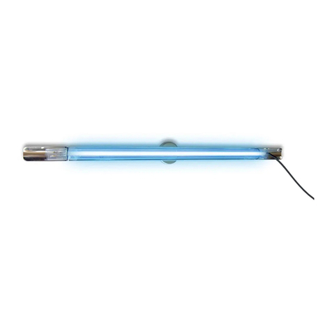
6Lamp Replacement
The germicidal UV lamp in APCO needs
to be replaced periodically. TUVL-1RT
lamps should be replaced every year.
TUVL-2RT should be replaced every 2
years. Note: UV lamps will continue to
emit visible light but lose germicidal
eectiveness over time.You can upgrade
to a 2 year lamp with your existing APCO
system.
CAUTION!
UV lamps contain small amounts of mercury - dispose of lamps in accordance with local
environmental regulations. For more information visit www.lamprecycle.org
Note: Use of replacement UV lamps other than Fresh-Aire UV® voids warranty.
TUVL-2RT (2 Year)
B
C
TUVL-1RT (1 Year)
IMPORTANT!
Systems with high 24 VAC loads may require the installation of a separate 24 VAC
transformer to power the UV light.
Always use a separate 24 VAC transformer with“communicating” air systems.
Draws 16 VA, may need to do load calculation: Volts under load X Amps under load.
Optional 2nd Remote UV Light
Installation Instructions
The optional Fresh-Aire Remote
UV Light works with the APCO
system for enhanced disinfection,
reduced system maintenance, and
improved indoor air quality.
MountingOptions
1Installation Notes
Before installing the Fresh-Aire Remote UV Light it is necessary
to determine the optimal mounting location inside the air
system. First, look for the area with the heaviest mold growth.
Also consider a location that will allow the germicidal UV
light to shine on the greatest surface area.
Some typical mounting locations:
ASupply-side duct
BAt the blower
CAcross top of coils
DCoil face
ECoil "A" plate
FReturn-side duct
A
B
C
D
D
E
F
Important: some materials inside the air system (including
lter media, ex duct, wiring etc.) may not be UV light resistant.
Use the optional UV shield (part #TUV-SHIELD-LP) or cover the
materials with reective tape.
WARNING
PROTECT EYES FROM UV LIGHT
TURN OFF UNIT OR DISCONNECT
BEFORE SERVICING
2Air Handler Interior Surface Installation
1. Determine the optimal position
for placement of the UV lamp.
2. Use a utility knife to cut a slit in the insulation
on the interior surface.
3. Place the magnetic “Z” bracket directly on the
metal surface or remove the magnet and hard-
mount the bracket using the self-tapping
screws provided. Use foil tape to close the cut
in the insulation.
4. Use plastic quick-nuts to attach the
UV lamp to the “Z” bracket as shown.
2.
3.
4.
P
3Coil“A” plate or Duct Installation
1. Snap the “Z” bracket apart by
bending.
2. Drill a 1” hole in the "A"-plate or duct
then attach the smaller piece of
the bracket using the self-tapping
screws.
3. Insert the UV lamp into the hole then
use the plastic quick-nuts to attach
the UV lamp to the “Z” bracket as
shown.
1.
2.
3.
P
IMPORTANT!
• APCO Dual lamps are wired in series - both must be connected for lamps to light
• Only qualified technicians should install this product
• Install in accordance with relevant building codes
• Read instructions carefully including safety warnings

7Lamp Replacement
The germicidal UV lamp in the Fresh-Aire Remote UV Light needs to be replaced
periodically. A TUVL-100 lamp should be replaced every year. The TUVL-200 should
be replaced every 2 years. Note: UV lamps will continue to emit visible light but lose
germicidal eectiveness over time. You can upgrade to a 2 year with your existing
power supply.
4Remote UV Light Conguration
IMPORTANT! Only the APCO RT Dual model
has the electrical capacity and attached cable
for the optional Remote UV Light. Simply
connect the lamp lead to the optional UV lamp
cable on the power supply (PART# ST/DT, SI/DI).
To add a second UV light to an existing APCO
system that is not a Dual model install a separate
Fresh-Aire UV AHU Series 1 or Blue-Tube UV
system.
Align Flanges
5Remote UV Lamp Connection
1. When all the other components are properly installed connect the UV Lamp
cable to the APCO Power supply cable.
2. Make sure the anges are aligned and then push the connectors rmly
together. A tight connection ensures a proper water-resistant seal.
2.
1.
TUVL-100
(1 Year)
TUVL-200
(2 Year)
Electronic
Power Supply
Eor F
Optional 2nd
UV Lamp
CAUTION!
UV lamps contain small amounts of mercury - dispose of lamps in accordance with local
environmental regulations. For more information visit www.lamprecycle.org
Note: Use of replacement UV lamps other than Fresh-Aire UV® voids warranty.
M N
6Sight Glass Installation
1. Find a suitable location on the outside
of the duct-work near the UV Lamp
installation and apply the Fresh-Aire UV®
warning/lamp replacement sticker.
2. Drill a ½” hole through the orange circle
on the sticker. Press the UV safety viewport
into hole.
3. Turn on the power and use the sight glass
to conrm that the UV Lamp is operating.
O

Duct Hole-Cut Template
Use scissors to cut away the circular or linear center of this template (dotted lines).
5”
4.25”
3.5”
Table of contents
Other Fresh-Aire UV Air Cleaner manuals

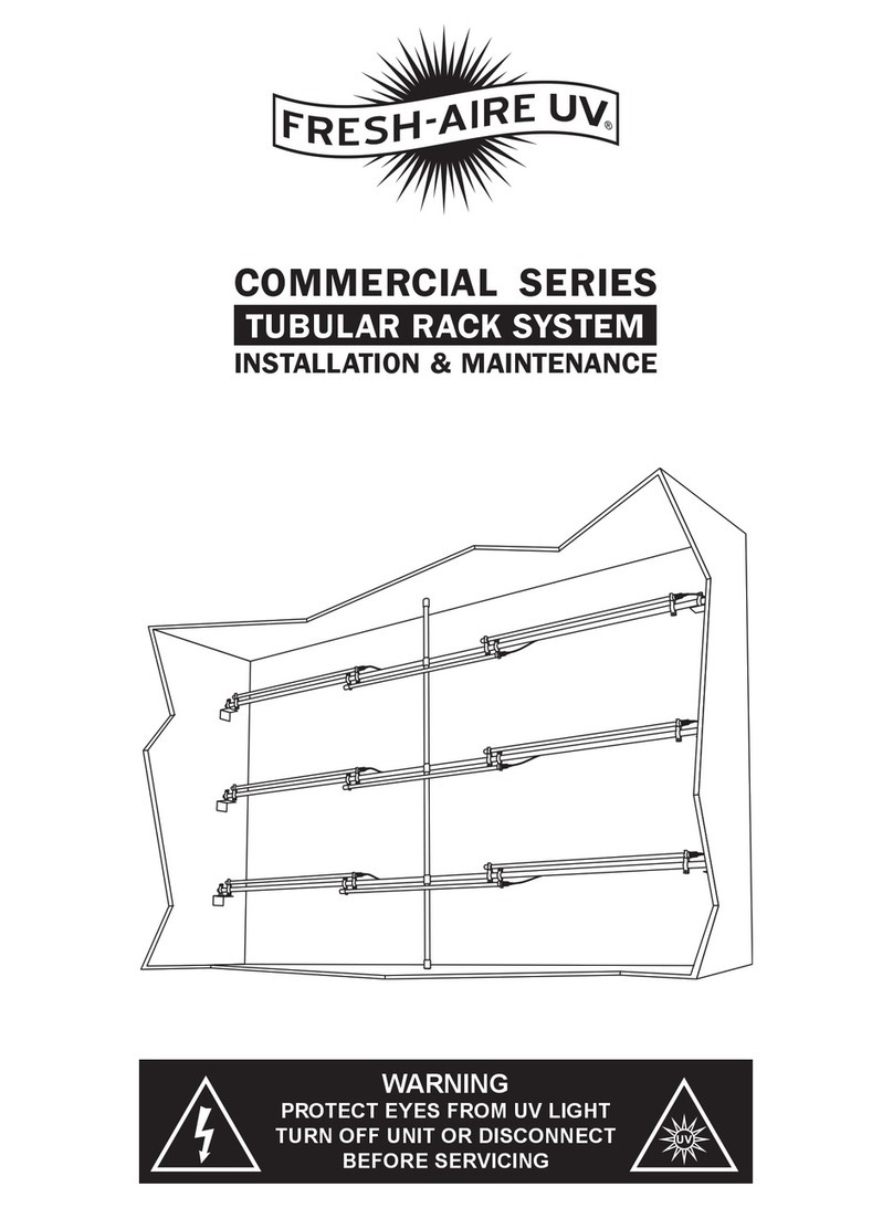
Fresh-Aire UV
Fresh-Aire UV COMMERCIAL Series Maintenance and service guide

Fresh-Aire UV
Fresh-Aire UV TIGHT FIT KIT User manual

Fresh-Aire UV
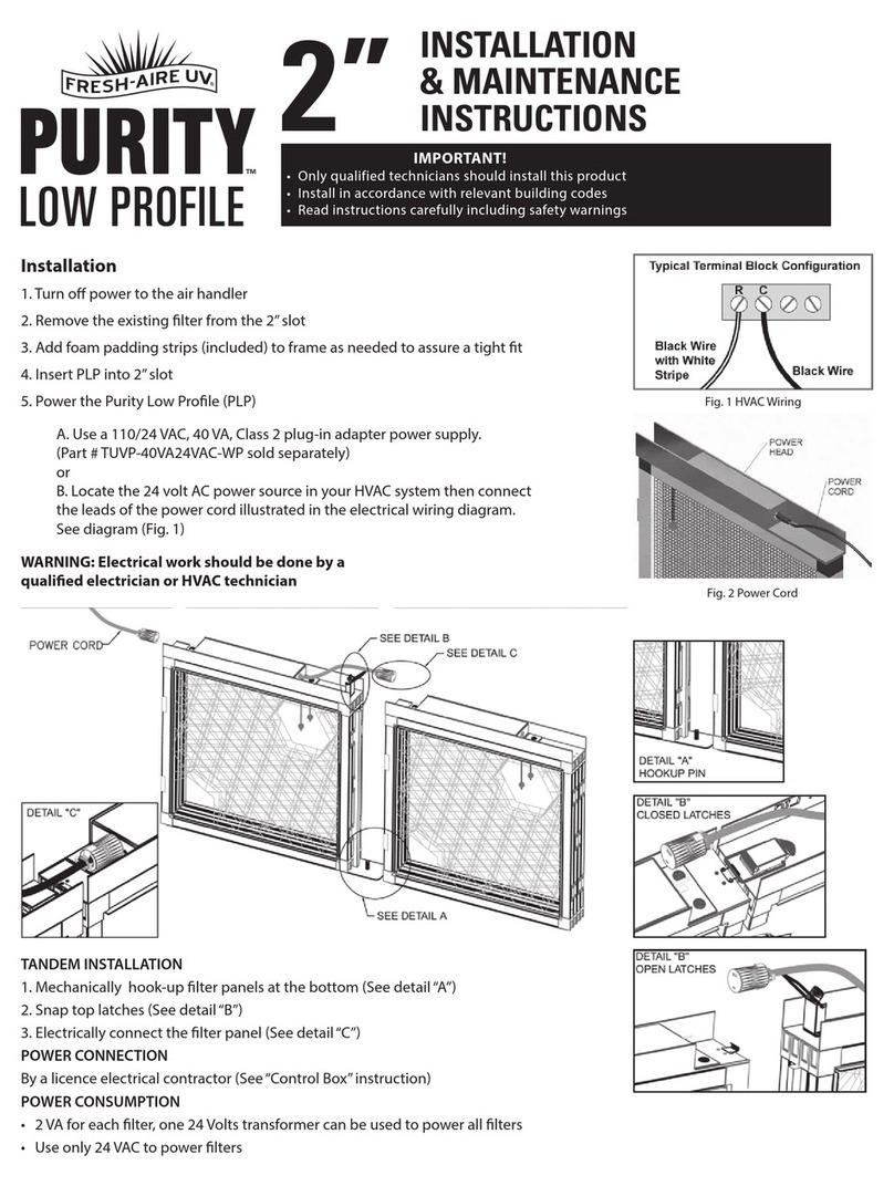
Fresh-Aire UV PURITY LOW PROFILE Installation and operating instructions

Fresh-Aire UV
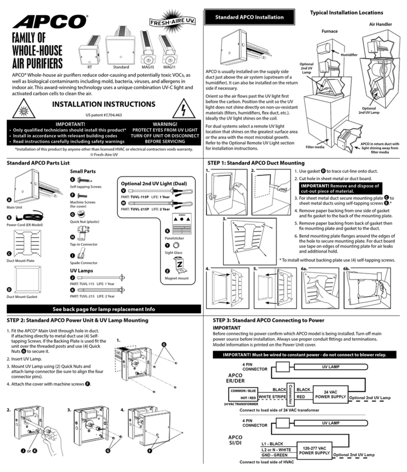
Fresh-Aire UV APCO Series User manual

Fresh-Aire UV
Fresh-Aire UV Blue-Tube UV-X User manual