- 2 -
Content
Manual Flyke....................................................................................................................................1
Content..............................................................................................................................................2
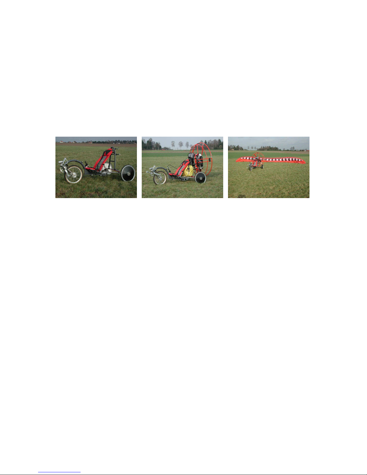
Manual Flyke....................................................................................................................................4
Introduction..................................................................................................................................4
Use of an existing motor..............................................................................................................4
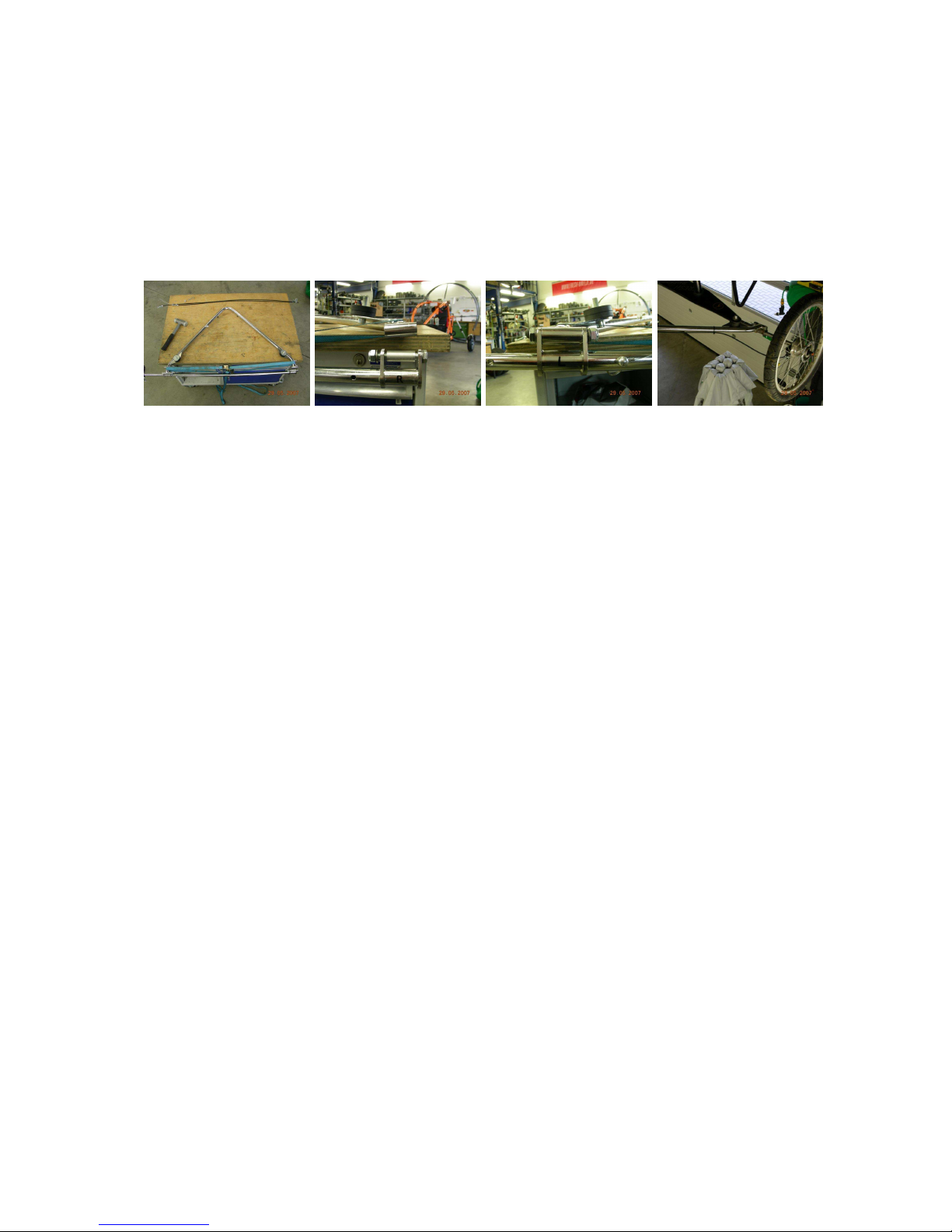
Setup.............................................................................................................................................5
Adjusting the Length...............................................................................................................5
Adjustments for different pilot weights..................................................................................5
Steering.....................................................................................................................................5
Option: wider rear axle............................................................................................................6
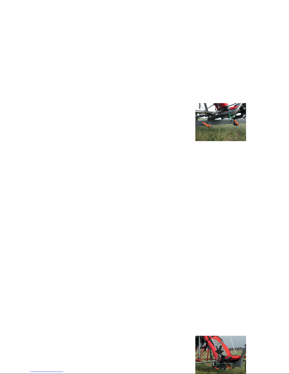
Braking.....................................................................................................................................6
Front Brake and Gear Shift.................................................................................................6
Rear Brake............................................................................................................................7
Operating Modes..........................................................................................................................7
Bicycle Mode...........................................................................................................................7
Flight Mode..............................................................................................................................7
Possible Combinations............................................................................................................7
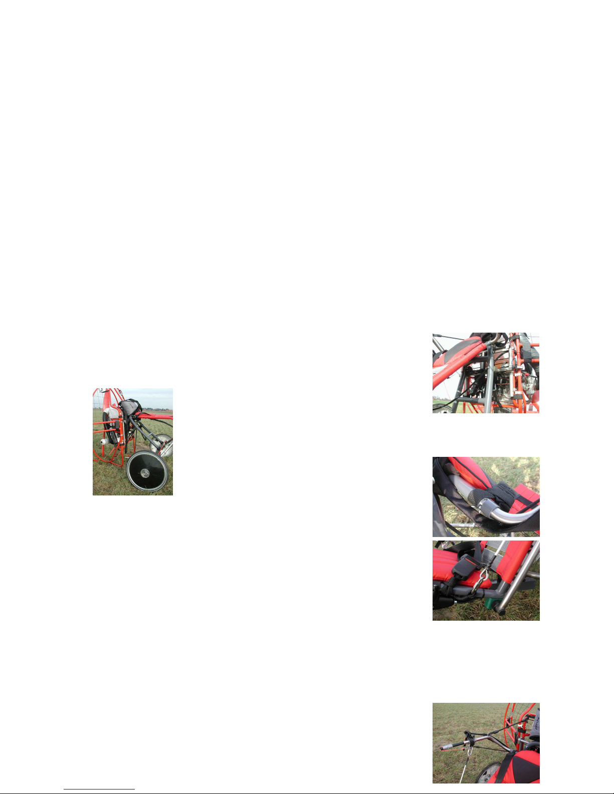
Assembly of the Motor, the Pushrods, the Paraglider and the Recovery System ..............8
Take-Off...................................................................................................................................9
General Information ..........................................................................................................10
The „Power-Steering-System“..........................................................................................10
The „Pulling-up Help“ ......................................................................................................10
Seat Belt .............................................................................................................................11
Start Check.........................................................................................................................11
Take-Off Procedure...........................................................................................................12
Flight.......................................................................................................................................12
Landing...................................................................................................................................13
Ground Transportation of the Paraglider with the Flyke ....................................................13
Something about the physical laws behind it...........................................................................13
Maintenance...............................................................................................................................14
Appendix: BulliX...........................................................................................................................15
Operation of the BulliX:...........................................................................................................16
Transportation, Disassembly:....................................................................................................16
Maintenance:..............................................................................................................................16