Fresh Breeze Relax 22 User manual

Manual
Relax 22/25

2
f
Anströmkante
Assembly drawing
Nameplate
Downsail
Leading Edge
Main Lines
Brake Lines
Brake Handle
Main Brake Lines
Riser
Carabiner
Stabilizer
Stabilizer Lines

New paragliders must have own in by the seller.
At the time of delivery, this paraglider meets the requirements of the German Airworthiness Claim LTF.
3
2. Important notes:
Reading this manual is mandatory!
The Relax paraglider may not be put into operation without careful reading of this manual
to avoid incorrect operation.
It should be noted that the structure is now a component of the entire aircraft (trike)
1.Dear RelaX Pilot
We are happy to welcome you in the circle of relax pilots. The RelaX was developed for those pilots
who enjoy a very good direction, high speed and a high maneuverability and do not want to give
up safety. The Relax is characterized by an exelentes handling, its directional stability while circling
and in the straight trip and its performance.
By air law, only a combination of all required components is permitted. This must be explained by a routine test
of the manufacturer.
This is especially important when exchanging individual components.
All information and properties of the RelaX necessary for ight operation are to a considerable extent inuenced
by the trike used. For this reason, also the manual of the trike must be considered.
We hereby expressly point out that in the case of improper operation of the entire device (as described in the manual),
no liability can be accepted.
Any change to the paraglider will invalidate the operating permission.
The pilot is responsible for the airworthiness of his entire aircraft and himself (aircraft, license, insurance,
inspections, tness).
The use of the paraglider is at your own risk! A liability of the manufacturer or distributor is excluded.
This manual has been prepared to the best of our knowledge and belief. However, from time to time
you have to look for updates under www.fresh-breeze.de

The linen locks are made of stainless steel and secured with an insert made of plastic against unintentional opening.
4
3. Target Group:
4. T echnical Describtion:
Construction:
The RelaX is a paraglider that has been specially developed for powered gliding with trike.
The RelaX was tested for the German airworthiness LTF.
The RelaX is not approved for free ight.
The material is made of air-impermeable ripstop nylon fabric D 40.
In this sythetically produced fabric a reinforced thread network is woven. This prevents tearing and increases
the tensile strength.
The coating makes the fabric water repellent, UV resistant and impermeable to air.
The Relax consists of 54 cells. The wing end is pulled down and integrated seamlessly into the cap.
The ventilation of the cap takes place via openings on the underside of the prole nose.
The transverse ventilation takes place through exactly sized holes (cross ports) in the rib.
Each supporting prole rib is hung on 4 line connections.
Tension bands are sewn in between the main line groups, which regulate the sail tension.
In the prole nose reinforcements are sewn in, which ensure high dimensional stability and stability.
At the inow and outow edge a stretch-poor band is sewn in. This ensures a uniform distribution of
stress throughout the cap.
Suspension:
Depending on the installation location, the lines of the RelaX are made of polyester-coated HMA aramid
and polyester-coated PES / Dynema. The strengths of the individual lines depend on the installation location
and vary between 100 and 340 daN.
The lines in the paraglider are divided into gallery lines, fork lines, main lines, stabilizer lines and brake lines,
as well as the main brake line.
The suspension lines are divided into A, B, C and D levels.
The lines of each level are dierent in color for ease of control.
In order to halve the braking forces at higher suspension weights (MTOW), the brake line is equipped with a pulley.
But attention. This also doubles the brake length by 100%.
The individual lines are shown in the lines plan.

5
m² 29,32
m 12,35
Streckung ausgelegt A/R 5,2
Nr 54
m² 25
m 9,6 7
A/R 3,74
Kg
Kg
Nachgewiesene Tragwerksfestigkeit Kg 430 bei 8 g Lastspitze
Kg 400 bei 6 g über 3 Sek unden
Kg 300 bei 8 g über 3 Sek unden
V-Trimm Km/h 50**
V-Max. Km/h >60**
* abhängig von technischen Daten des Trikeherstellers
** Abweichung aufgr und unterschiedlicher Abflugmasse möglich
Trim´s System:
The Relax has a trimmer system that changes the angle of attack of the glider and thus increases the speed.
The trim system extends the C and D risers and thus reduces the angle of attack of the paraglider.
In normal ight, all straps are the same length (38 cm with linen locks). When the trim system was activated,
the B straps would extend up to 2.5 cm, C straps by up to 6 cm, and the D straps by up to 12 cm. A-straps will not last longer.
It is recommended to set the trimmers sysmetrically at the start. At the instruction of the individual trike manufacturer
is to be paid in any case.
Function of the trimmer
The trimmer can easily be operated even under high loads. The built-in pulley allows this.
The illustration shows the strap in the accelerated position.
To bring the strap to the unaccelerated position, the handle / ball
(green arrow) is pulled down. Then all 4 straps are the same length.
For acceleration, the clamp buckle (orange arrow) is released slowly.
The rear straps are longer and the paraglider ies faster.
Trimmposition fast
5. Technical info´s
Area
Relax 25 Relax 22
Span at
5,2
26,39
11,71
Cells
Size projected
54
22
Span projected 9,17
A.R. 3,73
300
120MTOW min.
MTOW max.

6
6. Check the Paraglider
Each paraglider is surveyed and checked several times before delivery.
Nevertheless, new paragliders or those subjected to heavy duty should be examined according
to the following criteria.
Are all lines free of damage and correctly sewn?
Are all linen locks screwed properly
Are all webs sewn correctly and without damage?
Any damage, however inconspicuous it may be, must be assessed by the specialist and, if necessary, repaired.
A damaged paraglider is not able to y.
7. Adjusting the steering lines
The two main brake lines lead to a multi-branched line group, which are attached to the trailing edge of the paraglider.
On the risers, the two brake lines run through a pulley and are each connected to a brake lever
These control handles are attached during transport by means of two magnets on the strap.
The steering lines are set correctly at the factory.
This set point is permanently marked on the brake line. It must have at least 5 cm freewheel
8. Flight Operation
The following pages are not intended to be a guide to ying, and certainly not to replace ight instructor training
8.1 Prepare for Take O
Before each sart a thorough pre-ight check must be completed.
Check the riser, lines and cap for damage.
The lines locks must be closed and secured
If a defect is detected, it must not be started
The RelaX start best against the wind like an arc shape.
All lines must be well sorted and not devoured. Linen should not be under the sail.

7
Check list
Glider
- Glider without damage
- Riser without damage and not hung twisted
- Linen locks rmly screwed
- Lines without damage
- Carabiner closed correctly
8.2 Start
The RelaX is easy to start. The trimmer can also be open when starting, depending on the conditions.
The trim´s should be symetrical adjusted.
When the trimmers are fully closed, the glider is in trim position.
The further the trimmers are opened, the higher the overshoot tendency.
Also increases thereby the speed of departure and rolling distance.
8.3 Straight Flight
The speed in trim position is (depend on the load) 50km / h. In quiet air, the RelaX achieves
the minimum speed with 50-60 cm brake line operation.
In turbulent air we recommend to keep the brakes 5-15 cm pulled. This makes it dicult to undercut the cap.
All cm specications apply from the moment when the brake lines begin to grip.
8.4 Accelerated Flight
When the trimmer system is activated, the angle of attack changes. The speed increases up to 15 km / h.
With opened trimmers, the cap is more unstable and collapses lighter and heavier.
For safety reasons, the trimmers should be closed in case of turbulence. Never let the brake handles out of your hand.
Actuating the control lines should always be done carefully with the trimmer open. The brake line operation should
be reduced to a minimum length.
If the paraglider collapses once, the acceleration system must be deactivated immediately.
The paraglider then has to be stabilized via the brake lines.
8.5.Turning Flight´s
The RelaX is very agil, especially at high load. Brake pulses are converted directly without delay.
Excessive brake operation may cause a stall. Especially under full throttle or ying into a thermals

8
A one-sided stall announces itself early on.
The wing inside curve becomes soft and stops almost.
The brake is to be released on this side immediately.
8.6. Active Flying
Through active ying, collapses can often be prevented!
Active ying means braking impulses to keep the paraglider stable. The glider should be in the best position
if the glider is in the center above you.
When you y into thermals, the angle of attack increases. The brakes should now be opened.
When ying in downwind (falling out of the thermals) the brakes should be pulled.
8.7.Landing
The RelaX is easy to land.
The landing should always be against the wind direction.
In the nal approach, keep the paraglider calm with little braking work. Do not start braking too soon.
The kinetic energy in the aircraft is only once available when landing and is used so that the sinking speed
and the speed can be maximally reduced.
Do not drop the paraglider on the front edge after tough down.
9. Extreme Situations
9.1.Asymmetric collaps
The lateral collapse is probably the most common disturbance in paragliding.
This usually only occurs on the outer wing of the RelaX.
In order not to turn away, the brake must be countered on the other side.
The speed of the engine should be drastically reduced.
If it is a strong lateral Einklapper, may be countered only very metered. Heavy braking could cause a stall
By pumping on the folded side, the opening of the cap can be accelerated.
If the driver does not intervene on the lateral collapse, the paraglider usually recovers automatically after 1 revolution.
However, one should not rely on this, because in strong tubulence, an independent unfolding can also be prevented,
and the paraglider goes over into a steep spiral. That should be prevented in any case.
9.2. Cravat
If the paraglider does not open again by itself, a hangover could be the cause.
If that can not be changed and you are in low altitude, the rescue device should be triggered.
To solve a Cravat the following possibilities are possible:
9
t
Sensitive counter-braking. and through very fast and deep pull of the steering lines to reach the
reopening of the Pagarglider
Pull the color-coded stabilizer line
Attention!
The above maneuvers are very demanding and require a lot of height and skill. If insucient altitude
is available or the pilot feels overwhelmed, the rescue device should be triggered immediately.
9.3. Frontstall
The collapse of the entire front is usually done by sudden strong downdrafts.
Although this disruption looks spectacular, it is often not dangerous.
This does not cause any rotational movements and the paraglider opens quickly again by itself.
By metered braking the reopening can be accelerated.
9.4.Constant Stall
In a constant stall, the paraglider has no forward drive with simultaneous strong sinking.
A constant stall can be caused by:
- Too much engine thrust
-Einug in strong thermals
Strong air permeability of the paraglider fabric
-Tighten the C or D lines
- Wet paraglider
If you are in a stable stable, the thrust of the engine must be stopped. Also, the brakes must be released.
Do not use the brake lines. A full stall can happen in result
Under normal circumstances, the Relax start to ight within 2-3 seconds again at himself.
9.5. Full Stall
A fullstall is a complete stall with an uncontrollably collapsed cap.
This ight condition is very dangerous. Under no circumstances should you consciously y this maneuver.
This maneuver is caused by bilateral braking to total stall.
9.6.Spin
By pulling hard on a brake line, the ow on the half wing can break o.
This rear edge is then approached from behind and ies in reversed direction.
The paraglider then turns around the vertical axis.

10
There are several causes for spinning. For example:
A brake line is pulled too fast and too deep.
In slow ight is braked too much at the same time high engine thrust.
If a spin ends early, the paraglider goes into the normal ight without much loss of altitude.
If the spin is held longer, a one-sided collapse of the paraglider could be the result.
Also, the paraglider tends to overshoot to the front.
9.7. Wingover
If alternately tight curves are own left and right, this is called wing over. It is so easy to reduce a little height.
If the wingover is own too hard, the glider can get a large lateral collapse.
Aerobatics and maneuvers over 60 ° are not allowed and dangerous. Absolutely avoid!
9.8. Control without brake
Should the brake be out of action on the RelaX, it can be controlled with the rear risers (D).
The way to the stall is of course much shorter and is 5-10 cm.
10.Descents
10.1.Deep Spiral
The deep spiral is the safest way to quickly reduce altitude. However, there are large loads on material and pilot.
The high G-load signicantly increases the risk of losing consciousness.
If consciousness becomes cloudy or eyesight narrows, the spiral must be led out immediately.
You initiate the spiral by pulling the brake on one side. A shift of weight to the inside of the curve facilitates the process.
Lateral position and sinking speed increase rapidly.
Slight brake on the other side prevents folding in of the outer wing tip.
To release the brake is carefully opened again.
Should the spiral spiral be stable, it must be braked on the opposite side.
A quick escape of the spiral leads to strong commuting of the paraglider.
A deep spiral always results in a big loss of height. Be careful of sucient height.

11
Almost every paraglider eventually reaches the rate of descent, where the cap aligns with the openings down
and remains here in a stable position.
From such a stable situation, the paraglider then comes out only by dosed counter-braking.
A stable deep spiral creates high G loads and requires a great deal of eort to escape.
10.2.Big Ears
The so-called "Big Eears" is a simple, not too eective descent aid, for non-motorized paragliders
in which the forward speed is higher than the descent speed. It is more suitable for that
to reduce glide performance and to get distance horizontally from a hazard source rather than descend quickly.
For motorized trikes this maneuver makes no sense and must not be own.
10.3. B Stall
The B-stall is not to y for Trike structures by the high wing loading in principle. For this reason
this ight maneuver may not be own.
11.Care, storage, repairs, disposal
Life in the air depends on the condition of the structure. A well-maintained and properly treated paraglider
can reach twice the age. So that the Relax carries his pilot as long as possible and safely through the air,
the following points must be observed:
Maintenance
UV rays of the sun cause the material to age prematurely
Check the entire paraglider after tree and water landings
Do not pull the paraglider over the ground. The surface coating suers.
Wetness damages the coating and shortens the lifespan of the paraglider
Do not step on the lines
Do not kink the lines
When in contact with salt water, rinse immediately with fresh water
Only clean the paraglider with water. Do not use any chemicals, as they can damage the surface

12
12
Storage
The paraglider must always be stored dry.
The paraglider must not be stored together with chemical gases and vapors.
The paraglider must not be exposed to high temperatures. For example, the interior of a car in the summer.
Repairs
Small damages in the fabric, which do not run along the seam, can be repaired provisionally with the supplied adhesive tape.
All other repairs and check´s may only be carried out by an authorized specialist company.
Only original spare parts may be used
Any changes to the structure will invalidate the operating permit.
The RelaX must be checked every 2 years or every 100 operating hours.
Disposal
Please return disused paraglider to the manufacturer. The disposal happens here professionally.
For the sake of the environment.
Let's do this sport as much as possible in harmony with nature.
12. Enviroment
13. Line lengths
Name of the lines
All lines are described by Independence according to the same scheme.
Linen are ordered according to the explanation below, indicating the model and size.
The rst digit indicates the Lines level. (A, B, C, D K = brake)
The numbering starts from the middle and continues until the stabilizer
The top-lines are called starting from the middle as for example A5.
The Stabillizer line has the additional designation„E“
"For example: B4E = B Stabilizer at the top of the cap (RelaX 25 71.5 cm
The middle lines have the designation "M".
Example: CM4 = 4th centerline at C level. (Relax 25 M: 155 cm)
The main lines (Stammleine) have the attachment designation "R". Example: AR3 = A-Line from the middle of the Paraglider

13
61
73
69
86
86
86
83
85.5
90.5
90
94.5
91
95
101
81.5
101.5
97
101.5
108.5
75
81.5
109
104
109
117
104
107
102
106.5
116.5
97
103.5
98
103
114
101
105
105.5
100
105.5
116.5
109
113
107
113
124
122.5
111.5
105.5
111
123
129.5
105
104
106
100
106
118
125
115.5
108
101.5
107.5
119.5
127
124
116
109.5
116
127
134.5
138.5
463
151
151
469
139
139
470
129
129
349
83
65.5
83
61.5
83
69.5
463
151
51 1
946
139
1 93
704
912
129
463
151
151
4 96
139
139
470
129
21 9
129
291
83+22 5
242
138
129
216
147
147
216
71 3
173
4 36
511
151
946
139
139
1234
5
6
7
8
9
10
11
12
13
14e
1234567
89
10
11
12
13
14
15
16
17
A Riser
A Riser
A Riser
B Riser
C Riser
C Riser
B Riser
D Riser
B Riser
D Riser
C Riser
B Riser
13.1. Lines Lengths Relax 25

a.1 Einzelleinenlängen Relax 22
Handbuch Relax 11/2017 13.1

b.1Tragegurtlängen Relax 22
mm normal beschleunigt
A 375 375
A` 375 375
B 375 400
C 375 435
D 375 495
Längen gemessen vom Einhängepunkt Tragegurt bis Unterkante Schraubschäkel
No A B C D E Brake
1 7280 7220 7265 7360 7430 7880
2 7195 7130 7190 7285 7360 7735
3 7185 7120 7165 7270 7345 7640
4 7230 7165 7215 7325 7385 7515
5 7185 7120 7170 7265 7515
6 7120 7055 7100 7200 7430
7 7100 7030 7080 7175 7290
8 7130 7065 7110 7200 7250
9 7065 7010 7045 7120 7195
10 6995 6945 6970 7040 7155
11 6925 6885 6905 6970 7215
12 6845 6810 6820 6860 7165
13 6470 6470 6435 6505 7105
14 6390 6395 7130
15 7110
16 7055
17 7040
Handbuch Relax 11/2017 13.2
Relax 22

14
No A B C D E Brake
1765076057715789079658230
2757075157635782078908085
3756075107615780078758000
4761075707665785579207885
575607515762578057900
674857450755077307810
774707430752577057680
875057470755577307640
974307400749075707600
10 73557325741574857560
11 72807265735074107630
12 71907180725073057575
13 683068207510
14 67306745678568657575
15 7570
16 7525
17 7525
mm normal beschleunigt
A 375
A`
B 400
C 435
D 495
375
375 375
375
375
375
13.2.Total Length RelaX 25
13.3.Riser Lengths
All lengths are measured from the shoulder strap to the bottom sail
All lengths are measured from the point of attachment to shackles

15
Inspections
Checks must be carried out by a specialist company. This is responsible for their work itself.
Fresh Breeze is not responsible for any checks it has not performed by itself.
Every paraglider is subject to the inspection obligation
The test is carried out by the manufacturer or an authorized person.
It is also allowed by law to check the paraglider itself. However, we do not recommend this,
because neither expertise nor the necessary equipment is usually available.
If the paraglider itself is tested, third persons may not y with it.
If a defect is found, it must be repaired by the manufacturer before the next ight.
14.2. Check Intervals
Commercial:
Each year
or
every 100 hours
Privately used:
Every 24 months
or
every 100 h
14.3.Personnel requirement for check
Possession of a valid license
Type-related training on the paraglider
Vocational training related to this matter
2 years of professional experience in the production and testing of paragliders
14.1. Check

16
14.4. Necessary documents
Device data sheet
Routine test certicate
Maintenance and calibration records of measuring instruments
Airworthiness directive of the manufacturer
14.5. test steps
Identication of the paraglider
Visual inspection and identication of the paraglider
Check the type chart
Visual inspection of the cap
Examination of:
topsail
Bottom sail, leading edge
ribs
cell walls
Flares and lineloops
coating
and enter in the log
Visual inspection of the lines
Check the lines for damage, creases and chang, as well as the seams of the linen
Visual inspection of the risers
Check by:
shackles
chang
Trim's
wear
Maximum length dierence of the two risers max + - 5 mm

17
e
The individual lines are laid out and loaded with 5 daN. The measurement is made from the mount point
of the carrying strap up to the cap including the leash loop. The rib numbering starts in each case in the
Wing center with the wing sides are seen in the direction of ight. The determined total line lengths
are documented in the inspection report and the target line lengths of the corresponding type rating sheet
compared. The measurement of the opposite wing side can, assuming equal conditions,
can be performed by a symmetry check. Compliance with the manufacturer's instructions
The tolerances to be taken shall be documented in the verication report.
• Limit values (tolerance values) may deviate a maximum of +/- 15 mm from the type designation sheet,
whereby due to the tolerances no signicant trimming shift is allowed. The tolerances of the brake lines
are +/- 25 mm deviation from the type rating sheet.
• It is restrictive that a ne trimming must be made in 2 cases (the procedure must be followed in the
case of Manufacturer):
o if more than 50% of the lines reach the tolerance limit, with the tolerance limit
may only dier in either + or - direction (all values of
10-15 mm).
o or 25% of the lines deviate from the tolerance limits in both directions (+ or -)
(Example: A / B lines are 10-15mm longer, while the C / D lines are 10-
15 mm shorter than in the type label (trim shift to the rear due to aging)
Control of the linen strength
• Main line: From each line level (A, B, C), one main line is removed from the middle of the screen
and determine the breaking load with the tensile tester. The removed lines are in the inspection report.
to rename (e.g., A1, B1, C1, D1 in the left direction). This is important for a later review
does not test the line replaced in the previous test. At the 3rd and 4th inspection
Chests are checked next to the middle stem line (i.e., A2, B2, C2). From the 5th inspection begins
the turn again from the beginning (for example, A1, B1, C1 in the direction of ight left, according to the
rst inspection).
• Galerieleinen: Above the main lines a further leash is extended up to the cap
and also determines the breaking load. Is the determined breaking load of the upper A-plane or middle
A level at 1.5 times the setpoint (for example, setpoint 60 daN, determined breaking load> 90 daN),
then one can
Testing of further levels above the main lines at the B / C / D / E levels is omitted.
• Limits of individual lines for the Relax 25:
Main lines: A / B: 220 daN; C / D: 200 daN
Middle level: A / B: 120 daN; C / D: 80 daN
Upper level: A / B: 60 daN; C / D: 45 daN

18
Control of cap strength:
• The cap strength test is carried out using the Bettsometer (B.M.A.A.aproved patent No. GB 2270768 Clive
Betts Sales). In this test is in the top and bottom sail in the area of A-lines
bumped a needle-thick hole and tested the cloth for its tear propagation resistance.
The limit of the measurement is set at 800 g and a crack length of 5 mm.
• The exact test procedure is specied by the operating instructions of the bedometer. The determined
measurement value is entered in the verication log.
Control of the air permeability of the cloth:
• Using a JDC textile watch, a porosity measurement is made on at least 5 points of the top sail
(with at least 2 measurement points in the middle third of the screen) and at least 3 points of the
Untersegels performed. The determined values are documented in the verication report. The measuring
Points on the upper / lower sail are distributed over the span about 20-30 cm behind the inow edge.
• Limit values: no measuring point may reach a value of less than 10 seconds. Returns a measurement
a value less than 10 seconds, the paraglider loses its operability.
Control of trim and adjustment:
• All lines are to be checked according to the linen overview plan, if they were also properly lulled, and that
also all linen levels are free. Likewise, the brake lines are to check that everything is properly tucked in
and is free.
• The visual inspection must correspond exactly to the linen overview plan.
Check ight:
• Check ights are only required for major repairs.
• During check ight it must be determined if the ight characteristics of the structure to be checked
have changed compared to a brand new device.
• The examiner must be able by his ying skills and experience to be able to comply with the building
regulations to compare the ight behavior of the structure to be checked and possibly changed properties
determine. This includes above all things:
• that the pattern and its characteristics / ight behavior are known to the examiner.
• Also, the building codes in force at the time of approval of the design
be known.
• A check ight must have at least the points Winding up, Tipping, Ten
to negative curves, control path lengths,> 50% unilateral folding.
• If the device under test does not behave properly in any way, you may use this device
Device can no longer be own and must be checked by the manufacturer. under no circumstances
You may try to x the error yourself.
Other scheduled examinations:
• control of the linen stretch:
All innermost leashes should rst be measured under a load of 6 daN and then for 5 sec.
to charge customers with 20 daN and then again under 6 daN to measure. This activity is
conditionally before the measurement of the line lengths and the elongation values in the
verication protocol hold.
This manual suits for next models
1
Table of contents
Other Fresh Breeze Aircraft manuals

Fresh Breeze
Fresh Breeze Flyke User manual

Fresh Breeze
Fresh Breeze APAX evo User manual

Fresh Breeze
Fresh Breeze Monster Operation instructions

Fresh Breeze
Fresh Breeze XCitor User manual

Fresh Breeze
Fresh Breeze X-Light F 23 Technical specifications

Fresh Breeze
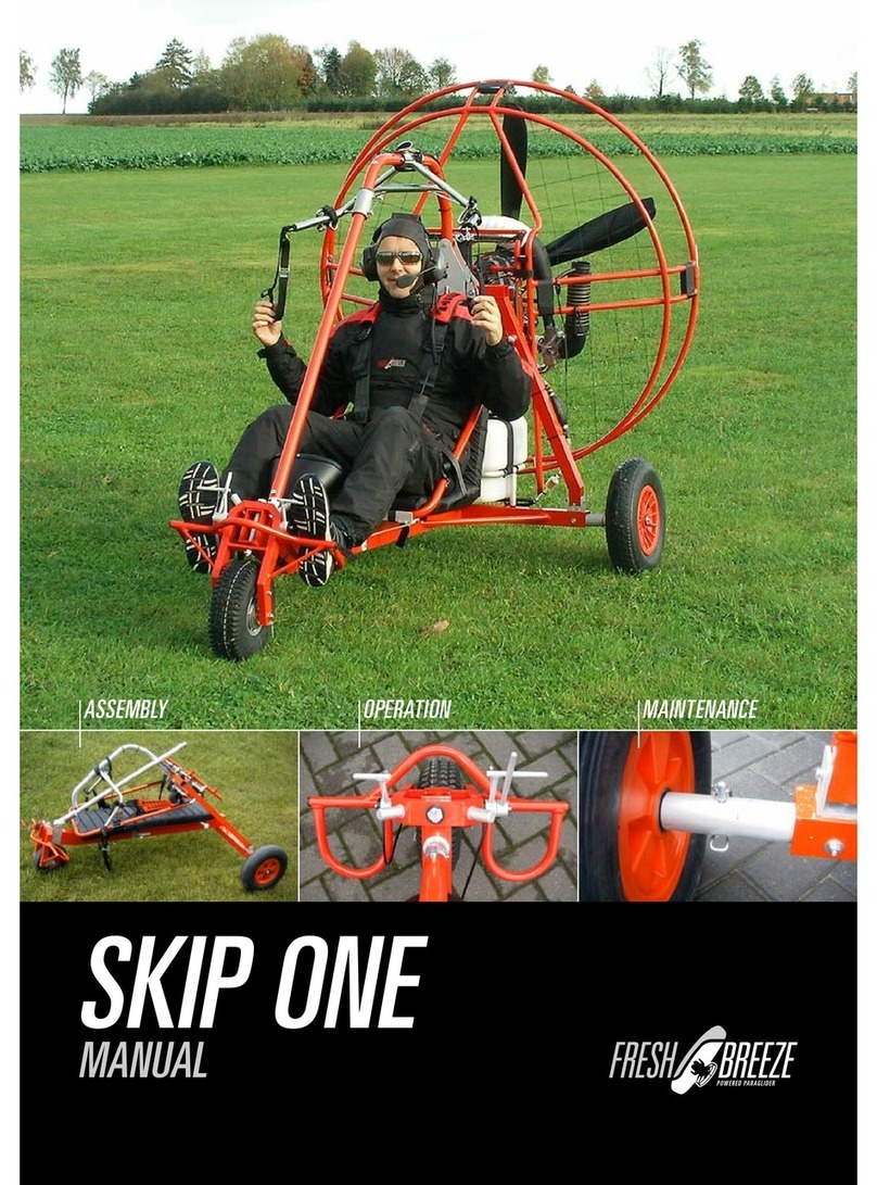
Fresh Breeze SKIP ONE Owner's manual

Fresh Breeze
Fresh Breeze Super Throxi User manual

Fresh Breeze
Fresh Breeze APAX User manual

Fresh Breeze
Fresh Breeze SilexX User manual