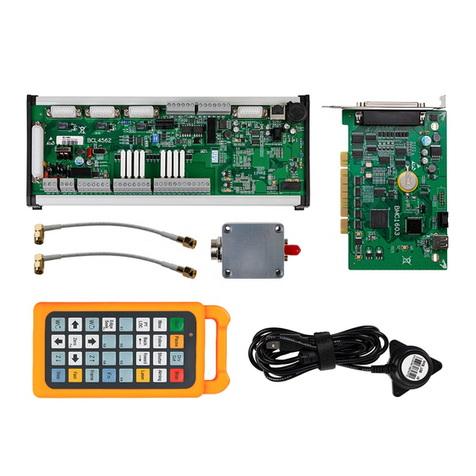
Friendess FSCUT2000E User manual

装机手册
FSCUT2000E User Manual

FSCUT2000E User Manual
2
Table of Contents
Table of Contents ................................................................................................................................ 2
Chapter 1 Overview ............................................................................................................................ 4
1.1 Introduction ...........................................................................................................................4
1.2 System Diagram ....................................................................................................................4
1.3 Product Details ......................................................................................................................5
Chapter 2 Wiring Instruction .............................................................................................................. 6
2.1 BMC228A Installation .....................................................................................................6
2.1.1 Dimension Diagram ...................................................................................................7
2.1.2 Installation Diagram ............................................................................................... 7
2.1.3 Ethernet Terminal ................................................................................................... 9
2.1.4 PCIE Socket ..........................................................................................................10
2.2 BCL4566E Wiring ........................................................................................................... 11
2.2.1 Interface Layout ....................................................................................................12
2.2.2 J01 Power Supply ................................................................................................. 12
2.2.3 J02PWM/DA Terminals ....................................................................................... 13
2.2.4 J03/J04/J05 Output Terminal ................................................................................14
2.2.5 J06/J07/J08 Input Terminal .................................................................................. 14
2.2.6 J09/J10 Network Interface ....................................................................................16
2.2.7 J11 Sensor Interface ..............................................................................................16
2.2.8 J12DB15 Servo Axis Interface ............................................................................. 16
2.3 Cutter Wiring ................................................................................................................... 20
2.3.1 ProCutter Wiring ...................................................................................................20
2.4 Laser Wiring .................................................................................................................... 21
2.4.1 IPG_ YLS Germany ............................................................................................. 21
2.4.2 IPG American ....................................................................................................... 22
2.4.3 RayCus ..................................................................................................................23
2.4.4 Trumpf .................................................................................................................. 24
Chapter 3 Installation ........................................................................................................................25
3.1 Installation Steps ..............................................................................................................25
3.1.1 Step 1. Install BMC228A Control Card ............................................................... 25
3.1.2 Step 2. Install BMC228A Driver ..........................................................................25
3.1.3 Step 3. Connect Slave ...........................................................................................26
3.1.4 Step 4. Scan in Cypfig .......................................................................................... 26
3.1.5 Step 5. Use CypCutE ............................................................................................ 26
Chapter 4 Precautions ....................................................................................................................... 27
4.1 Wiring Precautions ...........................................................................................................27
4.1.1 Drag Chain Wiring ................................................................................................27
4.1.2 Machine Tool Wiring ............................................................................................29
4.1.3 Assembly Requirements ....................................................................................... 31
4.2 Troubleshooting ............................................................................................................... 31

3
FSCUT2000E User Manual
4.2.1 Device Manager cannot find PCIe devices .......................................................... 31
4.2.2 Device Manager cannot install driver .................................................................. 32
4.2.3 Bus Scan failed ..................................................................................................... 32
4.2.4 Bus network alarm ................................................................................................33

FSCUT2000E User Manual
4
Chapter 1 Overview
1.1 Introduction
FSCUT2000E is a cost-effective CNC system for laser cutting. It is based on EtherCAT bus
technology and capable of motion control, laser control, and cutting gas control. It is common used
in sheet metal, kitchen ware, lamps and such industries. This user manual is only for installation
guidance.
1.2 System Diagram
FSCUT2000E includes the bus BMC228A Control Card, the bus IO board, and the bus height
controller, among which the BMC228A control card integrates the EtherCAT master protocol
stack.
The wiring diagram of non-BLT cutting head is shown in Figure 2.
Figure 2 Wiring diagram of FSCUT4000E - non-BLT cutter

5
FSCUT2000E User Manual
1.3 Product Details
FSCUT2000E bus CNC system includes BMC228A Control Card, BCL4566E terminal
board, WKB V6, amplifier and related cables.
FSCUT2000E packages contain hardwares and quantity that might be slightly different. Please
consult Friendess customer support if any questions.
BMC228A Control Card
(1)
WKB V6
(1)
BCL4566E Terminal Board
(1)
SPC RF cable
(2)
Amplifier
(1)
HC four-core cable
(1)
LAN Cables
LAN-0 3X(3)
LAN-1X (1)
LAN-3X (1)
Table 1-2 FSCUT4000E - non-BLT cutter details

FSCUT2000E User Manual
6
Chapter 2 Wiring Instruction
2.1 BMC228A Installation
BMC228A Control Card is a motion control card based on the EtherCAT Its 1.0Ghz
main chip provides excellent overall performance and has passed Friendess stringent testing
standards.
BMC228A
EtherCAT Control
Card
Bus Protocol
EtherCAT Master Protocol
PCI Express
PCI Express2.0 (Gen2)
Power Supply
Powered by PCIe motherboard, max 12V/1A, no hot plug
Anti-interference
Level
ESD 3 (6kV contact, 8kV air), EFT 4 (4kV power supply, 2kV signal),
Surge international 2 (2kV AC line, 1kV DC line)
Dimension and Weight
Dimension
(L x W x H) 127.6mm x121.0mm x21.45mm
Weight
80g
Feature
Cooling
Nature Cooling
Operating
Environment
0~+60℃
Storage temperature
-20~+70℃
Humidity
0% to 90% (non-condensation
Certification
CE
Environment Requirement
The waterproof and dustproof grade of the Control Card is IP00, unprotected. Please place the
computer in a clean, dust-free environment.
Table 2-1 BMC228A Technical Data

7
FSCUT2000E User Manual
2.1.1 Dimension Diagram
BMC228A Control Card dimension ( mm) is shown in Figure 3.
Figure 3 BMC228A Dimension
2.1.2 Installation Diagram
Install BMC228A in the socket of PCIE X4 and up with even force (refer to ②), and
secure its blank screw (refer to ①). Be aware of the heat dissipation for BMC228X and keep it
away from other cards as far away as possible. Refer to the diagram below.

FSCUT2000E User Manual
8
Figure 4 BMC228A Control Card Installation
BMC228X installed is shown below.
Figure 5 BMC228A Control Card After Installation

9
FSCUT2000E User Manual
2.1.3 Ethernet Terminal
The standard socket of BMC228A is RJ45 that can be used to connect EtherCAT slave
devices(servo drives, BCS100E, BCL2720E, etc.)
Label
Description
LED Color
Status
Description
1: Speed
Ethernet
communication
connection
speed
Green
Off
10 Mbps connection
Solid
100 Mbps conection
2: Link
Ethernet
communication
link status
Yellow
Off
No connection
Flashes
Communicating
Solid
Connected
Table 2-2 Description of RJ45 connection status

FSCUT2000E User Manual
10
2.1.4 PCIE Socket
BMC228A PCIE socket is X4 (Figure 6①)and can be used for X4, X8, X16. Its PCI Express
Protocol standard is V2.0 (Gen2) and the BMC228A motherboard requirements are as shown in
Table 2-3.
Figure 6 Gold Fingers
System
64-Bit Win7/10
CPU
Intel i3 8100 and up
Memory
4GB and up
PCIE Socket
X4 and up
PCI Express
PCI Express2.0 (Gen2) and up
Motherboard PCIE power
supply
12V/1A and up
Table 2-3 Motherboard Requirements

11
FSCUT2000E User Manual
2.2 BCL4566E Wiring
The BCL4566E bus height controller uses the EtherCAT bus to control the laser cutting
capacitive follower. It is a high-performance capacitive height controller.
BCL4566E
Terminal Board
Module
Qty
Description
Power Supply
/
24V DC /3.5A
DA
2
0-10V, 12bit, ±50mV
PWM
2
5V and24V, ±50KHz 0.3%
Common
Output
24
24V active high
1) The current of single output ≤ 0.7A
2) The current of all outputs ≤ 2.5A
Axis
1
Pulse digital quantity, PUL±/DIR± output, up to 600KHz
Dedicated
Input
27
IN1-IN24, active low, 0~ 15V
IN25-IN27, active high, 24~ 8V
Capacitance
Sensor
1
Capacitance frequency 2Mhz~4Mhz
Working
Environm
ent
/
Temperature: 0℃~60℃
Humidity: 10%~90%Rh(no(no condensation)
Dimension
/
300mm×123×34mm
Weight
/
640g
Table 2-6 BCL4566E Technical Data

FSCUT2000E User Manual
12
2.2.1 Interface Layout
BCL4566E interface layout of terminals
Figure 2 BCL4566E interface terminals
2.2.2 J01 Power Supply
Figure 3 Power Supply Terminal
The machine case is the negative pole of the measured capacitance. In order to ensure the
stable operation of the measurement circuit, the "FG pin" of the power interface must be reliably
connected to the machine case (that is, it is in good conduction with the machine case). The case
of the preamplifier of BCL4566E must also be connected with the machine case well. The
specific index is that the DC impedance is always less than 10 ohms, otherwise the EMC effect
may not be good.

13
FSCUT2000E User Manual
2.2.3 J02PWM/DA Terminals
Figutr 4 PWM/DA Terminals
BCL4566E has 2 channels of PWM pulse width modulation signal, the left channel is
24V level PWM. The right channel is 5V level PWM, and P- is the negative terminal of the
PWM signal. The duty cycle is adjustable from 0% to 100%, and the highest carrier
frequency is 50KHz. The signal output mode is shown in the figure below.
Figure 5 PWM Output Circuit
Note: 1) There are dedicated enabling relays for PWM+ and PWM- signals, and there is no need
for external relay isolation.
2) Wrong connection of 5V/24V PWM signal may cause damage to the laser.
BCL4566E has 2 channels of 0~10V analog output. DA1/DA2 is the positive terminal of analog
quantity, and D- is the negative terminal of analog quantity. DA1/DA2 can be configured as
the control signal of laser peak power and gas proportional valve in the "Cypfig" that comes
with CypcutE software.
Output signal
0V~+10V
Max Output
50mA
Max Error
+/-10mV
Resolution
2.7mV
Conversion
400us

FSCUT2000E User Manual
14
2.2.4 J03/J04/J05 Output Terminal
Take J03 as an example, the interface diagram is as follows.
Figure 6 Output Terminal
J03-J05 has a total of 24 high-level (24V level) outputs. The above figure is the wiring
diagram of J03. O1-O8 are the positive terminals of the output port, and COM is the negative
terminal of the output port. The 24 output ports can be configured as control interfaces ,
e.g."laser", "cutting head", "auxiliary gas", "alarm" and "pallet changer” etc. in the "Cypfig"
that comes with CypcutE software.
Note: 1) The maximum current of one output port is 0.7A, otherwise the short circuit
protection will be triggered.
2) The total current of the output ports cannot exceed 2.5A, otherwise the short
circuit protection will be triggered.
2.2.5 J06/J07/J08 Input Terminal
Take J06 as an example, the interface diagram is as follows.
Figure 7 Input Terminal
J06-J08 has a total of 27 input ports. IN1-IN24: active low (0~15V), high level (19-24V) has no
conduction; IN25-IN27: active high(24~8V conduction), low level (0~4V) has no conduction.
Take J06 as an example, I1-I9 are the positive terminals of the input port signal, and COM is
the negative terminal of the input port.
The typical connection of the photoelectric switch is as shown in the figure below. An NPN 24V
photoelectric switch should be used.

15
FSCUT2000E User Manual
The typical connection of the contact switch is shown in the figure below.
The typical connection of the magnetic induction input switch is shown in the figure
below. An NPN 24V magnetic induction switch should be used.

FSCUT2000E User Manual
16
2.2.6 J09/J10 Network Interface
J09 is the EtherCAT network output interface, and J10 is the EtherCAT network input interface,
supporting 100Mbps network communication. It is recommended to use standard RJ45
network cables in CAT5E or up for bus communication
Description of RJ45 connection status of network terminal
Label
Description
LED
Color
Status
Description
1: Link
EtherCAT Bus
Connection and
Communication
Status
Green
Off
No connection
Solid
Connected, without
communication
Flashes
Connected, with
communication
2: Status
EtherCAT Bus
Link Status
Yellow
Off/Flashes
Not in the OP state
Solid
in the OP state
2.2.7 J11 Sensor Interface
Figure 8 Sensor interface
The 4-core signal transmission cable of the sensor can be made by yourself with a 3-core
shielded cable and two 4-pin plugs. 1, 2, and 3 cores are connected in pairs, and the 4th core
must be connected with a shielding layer. It is recommended to use the original cable to
ensure stability.
2.2.8 J12DB15 Servo Axis Interface
The control interface of BCL4566E focusing servo driver is double-row female DB15F, and the
pin definition of the corresponding wire is shown in the figure below:

17
FSCUT2000E User Manual
Figure 9 Servo drive interface
Axes are defined in the table below.
Servo Axis Interface Definition
15-pin Female Servo Control Interface
Pin
Signal name
Pin
Signal name
1 yellow
PUL+
9 yellow
black
PUL-
2 blue
DIR+
10 blue
black
DIR-
3 black
A+(encoder)
11 black
white
A-(encoder)
4 orange
B+(Encoder)
12 orange
black
B-(encoder)
5 red
Z+(encoder)
13 red
black
Z-(encoder)
6 green
SON(servo enable)
14 purple
ALM(alarm)
7 green
blac
k
-
15 brown
black
0V(power ground)
8 brown
24V(power output)
+24V, 0V: 24VDC power for the servo driver.
PUL: digital signal, pulse signal for the driver.
DIR: digital signal, direction signal for the driver.
SON: output servo drive enable signal.
ALM: Receive the alarm signal of the servo drive.
A+, A-, B+, B-, Z+, Z-: three phases of the encoder, input signal.
Please refer to the figure below for the wiring with the Yaskawa servo drive.
Yaskawa Servo Wiring

FSCUT2000E User Manual
18
Figure 10 Yaskawa Servo Wiring Diagram
Pay attention to the following when connecting drives in other brands:
1. Please first confirm the type of SON signal of the servo drive you choose and whether it is
active low (that is, it is ON when it is connected to the GND of the 24V power supply).
2. Make sure the parameter of the servo drive: the pulse signal received is "pulse + direction".
3. Confirm whether there is an external emergency stop signal input in the input terminal of the
servo drive, and its logic.
4. Before the test run of the driver, 24V power must be supplied to the terminal board first,
because the 24V power required by the servo is transferred through the terminal board.
5. If the drive still cannot run, make sure that the parameter is set to not use "POT/NOT".

19
FSCUT2000E User Manual
Figure 11 BCL4566E Wiring Diagram

FSCUT2000E User Manual
20
2.3 Cutter Wiring
2.3.1 ProCutter Wiring
The connection of ProCutter cutting head is shown in the figure below.
Table of contents
Other Friendess Control System manuals
Popular Control System manuals by other brands

Aurora Multimedia
Aurora Multimedia WACI NX+ Reference manual & programming guide

DoorKing
DoorKing 1620 Series installation manual

RIB
RIB RAPID N manual

Intelligent Motion Systems
Intelligent Motion Systems MicroLYNX-4 Quick manual

ACC
ACC SmarTouch Digital series User & Programmers Manual

Extron electronics
Extron electronics TLI Pro 101 user guide