Friendess FSCUT6000 User manual

Installation
FSCUT6000 User Manual

FSCUT6000 User Manual
2
Table of Contents
Table of Contents ................................................................................................................................ 2
1. Overview ......................................................................................................................................... 4
1.1. Introduction ......................................................................................................................... 4
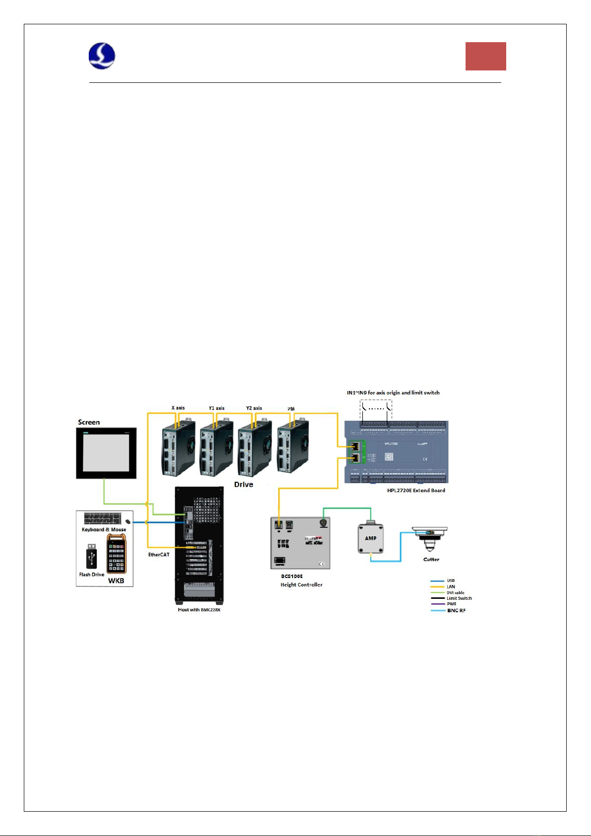
1.2. System Diagram ................................................................................................................... 4
1.3. Product Details .....................................................................................................................5
2. Wiring Instruction ........................................................................................................................... 8
2.1. BMC2282 Installation ...........................................................................................................8
2.1.1. Dimension Diagram ................................................................................................ 10
2.1.2. Installation Diagram ................................................................................................10
2.1.3. Ethernet Terminal ................................................................................................... 12
2.1.4. PCIE Socket ..............................................................................................................12
2.2. HPL2720E Wiring ............................................................................................................... 13
2.2.1. Interface Layout ...................................................................................................... 15
2.2.2. J01 EtherCAT Input Terminal ...................................................................................15
2.2.3. J02 EtherCAT Output Terminal ................................................................................15
2.2.4. J03 Power Input Terminal ....................................................................................... 15
2.2.5. J04 PWM Output Terminal ..................................................................................... 16
2.2.6. J05 DAOutput Terminal ...........................................................................................16
2.2.7. J06 Common Output Interface ............................................................................... 16
2.2.8. J07 Common Input Interface .................................................................................. 17
2.3. BCS100E Wiring ..................................................................................................................18
2.3.1. Interface Layout ...................................................................................................... 19
2.3.2. J01 Power Input Terminal ....................................................................................... 20
2.3.3. J02 Sensor Input Terminal ...................................................................................... 21
2.3.4. J03/04 EtherCAT IN/OUT Terminal ......................................................................... 21
2.4. Cutter Wiring ......................................................................................................................22
2.4.1. ProCutter Wiring .....................................................................................................22
2.5. Laser Wiring ....................................................................................................................... 23
2.5.1. IPG_ YLS German .................................................................................................... 23
2.5.2. IPG American .......................................................................................................... 24
2.5.3. Raycus ..................................................................................................................... 25
2.5.4. Trumpf .....................................................................................................................26
3. Installation .....................................................................................................................................27
3.1. Installation Steps ................................................................................................................27
3.1.1. Step 1. Install BMC2282 Control Card .................................................................... 27
3.1.2. Step 2. Install BMC2282 Driver ...............................................................................27
3.1.3. Step 3. Connect Slave ............................................................................................. 28

3
FSCUT6000 User Manual
3.1.4. Step 4. Scan in CypConfig ....................................................................................... 28
3.1.5. Step 5 Use CypCutPro .............................................................................................28
4. Precautions ....................................................................................................................................29
4.1. Wiring Precautions .............................................................................................................29
4.1.1. Drag Chain Wiring ...................................................................................................29
4.1.2. Machine Tool Wiring ...............................................................................................31
4.1.3. Assembly Requirements ......................................................................................... 33
4.2. Troubleshooting ................................................................................................................. 33
4.2.1. Device Manager cannot find PCIe devices ............................................................. 33
4.2.2. Device Manager cannot install driver .....................................................................34
4.2.3. Bus Scan failed ........................................................................................................ 34
4.2.4. Bus network alarm ..................................................................................................35

FSCUT6000 User Manual
4
1. Overview
1.1. Introduction
FSCUT6000 is CNC system for laser cutting and is very cost-effective. It is based on EtherCAT
bus technology and capable of motion control, laser control, and cutting gas control. It is common
used in sheet metal, kitchen ware, lamps and such industries. This user manual is only for installation
guidance.
1.2. System Diagram
FSCUT6000 includes the EtherCAT BMC2282 Control Card, the bus IO board, and the bus
height controller, among which the BMC2282 control card integrates the EtherCAT master
protocol stack.
The network cable is led out from the network port of BMC2282 and connected to the BLT
cutting head. The wiring diagram is shown in Figure 1.
Figure 1 Wiring diagram of FSCUT6000 - BLT cutter

5
FSCUT6000 User Manual
The wiring diagram of other cutting head is shown in Figure 2.
Figure 2 Wiring diagram of FSCUT6000 - other cutter
1.3. Product Details
FSCUT6000 EtherCAT CNC system includes BMC2282 Control Card, BCS100E terminal
board or BCS210E height controller, HPL2720E, WKB V6 and related cables, etc.
FSCUT6000 packages contain hardwares and quantity that might be slightly different. Please
consult Friendess customer support if any questions.

FSCUT6000 User Manual
6
BMC2282 Control Card
(1)
BCS210E Motion Control
(1)
HPL2720E Terminal Board
(1)
WKB V6
(1)
LAN-20X-PWE
(1)
LAN Cables
LAN-0 3X(3)
LAN-1X (2)
LAN-3X (1)
Table 1-1 FSCUT6000-BLT cutter details

7
FSCUT6000 User Manual
BMC2282 Control Card
(1)
BCS100E Motion Control
(1)
HPL2720E Terminal Board
(1)
WKB V6
(1)
Amplifier
(1)
HC 4-core cable
(1)
LAN Cables
LAN-0 3X(4)
LAN-1X (2)
LAN-3X (1)
SPC RF cable
(2)
Table 1- 2 FSCUT6000-other cutter details

FSCUT6000 User Manual
8
2. Wiring Instruction
2.1. BMC2282 Installation
BMC2282 Control Card is a motion control card based on the EtherCAT Its 1.0Ghz
main chip provides excellent overall performance and has passed Friendess stringent testing
standards.
BMC2282
EtherCAT Control
Card
Bus Protocol
EtherCAT Master Protocol
PCI Express
PCI Express2.0 (Gen2)
Power Supply
Powered by PCIe motherboard, max 12V/1A, no hot plug
Anti-interference
Level
ESD 3 (6kV contact, 8kV air), EFT 4 (4kV power supply, 2kV signal),
Surge international 2 (2kV AC line, 1kV DC line)
Dimension and Weight
Dimension
(L x W x H) 127.6mm x121.0mm x21.45mm
Weight
80g
Feature
Cooling
Nature Cooling
Operating
Environment
0~+60℃
Storage temperature
-20~+70℃
Humidity
0% to 90% (non-condensation
Certification
CE

9
FSCUT6000 User Manual
Environment Requirement
The waterproof and dustproof grade of the Control Card is IP00, unprotected. Please place the
computer in a clean, dust-free environment.
Table 2-1 BMX2282 Technical Data

FSCUT6000 User Manual
10
2.1.1. Dimension Diagram
BMC2282 Control Card dimension ( mm) is shown in Figure 3.
Figure 3 BMC2282 Dimension
2.1.2. Installation Diagram
Install BMC2282 in the socket of PCIE X4 and up with even force (refer to ②), and
secure its blank screw (refer to ①). Be aware of the heat dissipation for BMC228X and keep it
away from other cards as far away as possible. Refer to the diagram below.

11
FSCUT6000 User Manual
Figure 4 BMC2282 Control Card Installation
BMC228X installed is shown below.
Figure 5 BMC2282 Control Card Installed

FSCUT6000 User Manual
12
2.1.3. Ethernet Terminal
The standard socket of BMC2282 is RJ45 that can be used to connect EtherCAT slave
devices(servo drives, BCS100E, HPL2720E, etc.)
Label
Description
LED color
State
Description
1: Speed
Ethernet
connection
speed
Green
Off
10 Mbps
Solid
100 Mbps
2: Link
Ethernet link
status
Yellow
Off
No connection
Flashes
Communicating
Solid
Connected
Table 2-2 Description of RJ45 connection status
2.1.4. PCIE Socket
BMC2282 PCIE socket is X4 (Figure 6①)and can be used for X4, X8, X16. Its PCI Express
Protocol standard is V2.0 (Gen2) and the motherboard requirements are as shown in Table 2-3.

13
FSCUT6000 User Manual
Figure 6 Gold Fingers
System
64-Bit Win7/10
CPU
Intel i3 8100 and up
Memory
4GB and up
PCIE Socket
X4 and up
PCI Express
PCI Express2.0 (Gen2) and up
Motherboard PCIE power
supply
12V/1A and up
Table 2-3 Motherboard Requirements
2.2. HPL2720E Wiring
HPL2720E is an IO extend board based on the EtherCAT bus, which supports the
peripheral resources required by the FSCUT6000 high-power cutting system, as shown in
Table 2-4.

FSCUT6000 User Manual
14
HPL2720E
Module
Qty
Description
Note
Power
Suppl
y
/
24V DC/5A
PWM
1
24V, ±50kHz 0.3%
Max 50kHz,3%
DA
4
0-10V, 12bit, ±20mV
Common
Outpu
t
20
High level 24V output, ≤ 0.7A per channel
The total current output ≤ 2.5A
External relay
recommended
Common
Input
27
24V level, active low (<15.6V); IN1~IN3 can be
switched to active high (>5.8V)
Working
Environment
Temperature: 0~60℃
Humidity: 10%~90% (no condensation)
Dimension
195×118×45.2mm
Weight
480g
Table 2-4 HPL2720E Hardware Resources

15
FSCUT6000 User Manual
2.2.1. Interface Layout
The interface layout of the HPL2720E terminals is shown in the figure below.
2.2.2. J01 EtherCAT Input Terminal
EtherCAT network cable input interface, standard RJ45 network cable;
2.2.3. J02 EtherCAT Output Terminal
EtherCAT network cable output interface, standard RJ45 network cable;
2.2.4. J03 Power Input Terminal
Notice
24V and 0V are respectively connected to the positive and negative poles of the DC 24V
switching power supply; FG needs to be reliably connected to the ground, and the
ground wire should be as short and thick as possible.
All terminals are pluggable only, and disassembly is shown in the right figure above.
There is no need to unplug the terminals for wiring.

FSCUT6000 User Manual
16
2.2.5. J04 PWM Output Terminal
HPL2720E has a PWM pulse width modulation signal, which can be used to control the laser
power. The PWM signal level is 24V. The duty cycle is continuously adjustable from 0% to 100%,
and the max carrier frequency is 50KHz.
The signal output mode is shown in the figure below.
Note: The P+ and P- signals have enabled solid-state relays inside, and no external
relays are needed for isolation!
2.2.6. J05 DAOutput Terminal
HPL2720E has 4 analog outputs of 0~10V. The four-way DA can be configured as the
control signal of laser peak power and gas proportional valve in the "CypConfig" that comes
with CypCutPro software.
2.2.7. J06 Common Output Interface
OUT1~OUT20, total 20 high-level 24V outputs. In the "CypConfig" that comes with
CypCutPro, the output port can be configured as "height controller", "laser", "cutting head",
"auxiliary gas", "alarm", "pallet changer" and other related controls interface.
Output Signal
0~10V
Max Output
50mA
Max Error
+/-20mV
Resolution
2.7mV
Conversion
400us
Table 2-5 DA Output Parameter

17
FSCUT6000 User Manual
Note: Only DC loads can be connected, the output current of each channel must be ≤
0.7A, and the total current of the output port must be ≤ 2.5A, otherwise the short
circuit protection will be triggered.
If you need to connect to an AC load, please connect an external relay;
2.2.8. J07 Common Input Interface
HPL2720E does not set a dedicated input, and each input port can be set as limit/origin
signals.
The Normally Open and Normally Closed modes of the limit and origin signals can be set in
the "CypConfig" that comes with CypCutPro. When it is set to NO, the input is valid when
the input port is connected to 0V; when it is set to NC, the input is valid when it is
disconnected from 0V.
The typical connection of the photoelectric switch is shown in the figure below, and an NPN
type 24V photoelectric switch must be used;
The typical connection of mechanical contact switch is shown in the figure below;
The typical connection of the magnetic input switch is shown in the figure below. An NPN
24V magnetic induction switch must be used.

FSCUT6000 User Manual
18
Among them, IN1~IN3 can adjust the polarity of the effective level through hardware
jumpers:
2.3. BCS100E Wiring
The BCS100E bus height controller uses the EtherCAT bus to control the laser cutting
capacitive follower. It is a high-performance capacitive height controller.

19
FSCUT6000 User Manual
BCS100E
Height Controller
Module
Qty
Description
Power Supply
/
24V DC/1A
LAN port
2
EtherCAT slave network port, 100Mbps, left in and right out
Sensor interface
1
Capacitance detection control, height control range 0~25mm
Working Environment
Temperature: 0~60℃
Humidity: 10%~90% (no condensation)
Dimension
136mm×123×34mm
Weight
/
Table 2-6 BCS100E Technical Data
2.3.1. Interface Layout
The interface layout of BCS100E is shown in the figure below.

FSCUT6000 User Manual
20
2.3.2. J01 Power Input Terminal
The power terminal is connected to the positive and negative poles of the DC 24V switching
power supply to supply power to the BCS100E controller. FG needs to be reliably connected to the
ground, and the ground wire should be as short and thick as possible. The reliable grounding of the
screen shell can not only improve the stability of the system, but also prevent the screen or
interface from being damaged due to external static electricity or surge.
Pin
Note
FG
Shielding cover (internal short circuit with
0V)
0V
Power ground
24V
24V power positive
Table 2-7 J01 Power Input Terminal
Table of contents
Other Friendess Control System manuals
Popular Control System manuals by other brands

Ridder
Ridder HortiMaX-Go! CloudBoX quick start guide

UTC Fire and Security
UTC Fire and Security Chubb VS-MKII Installation, operation and maintenance manual

VRinsight
VRinsight Instrument RadioStack user manual

Juniper
Juniper JCS1200 Installing

Inovance
Inovance Monarch NICE Series user guide

Carel
Carel WM00E 00 Series quick start guide