Проверил: Р.Ч./07.2015г
PENDULUM ACTION JIGSAW
WARNING
Read this manual carefully before using the
machine, for your own safety.
SAFETY INSTRUCTIONS
When using the machine, always observe
the enclosed safety instructions as well as
the additional safety instructions.
Denotes risk of personal injury
or damage to the tool.
You will find the following symbols on the
machine:
Laser beam warning
Laser beam characteristics
ADDITIONAL SAFETY INSTRUCTIONS
FOR JIGSAWS
Make sure that the saw blade is mounted
correctly before use.
Make sure that, when in use, the guard is
pressed down as far as possible.
Never load the machine so much that the
motor is coming to a standstill.
Never try to brake the saw blade after the
machine has been switched off.
Use original accessories only.
ADDITIONAL SAFETY INSTRUCTIONS
FOR LASERS
Warning! The laser beam potentially
causes severe eye damage. Never look or
stare directly into the laser beam.
During use, do not point the laser beam at
people, directly or indirectly through reflecting
surfaces.
This laser complies with class 2 according
to EN 60825-1/A11, 1996. The unit
includes no servicing components. Do not
open the housing for any reason. If the
unit is damaged, have the damage
repaired by an authorized repair agent.
ELECTRICAL SAFETY
Always check that the power supply corresponds to
the voltage on the rating plate.
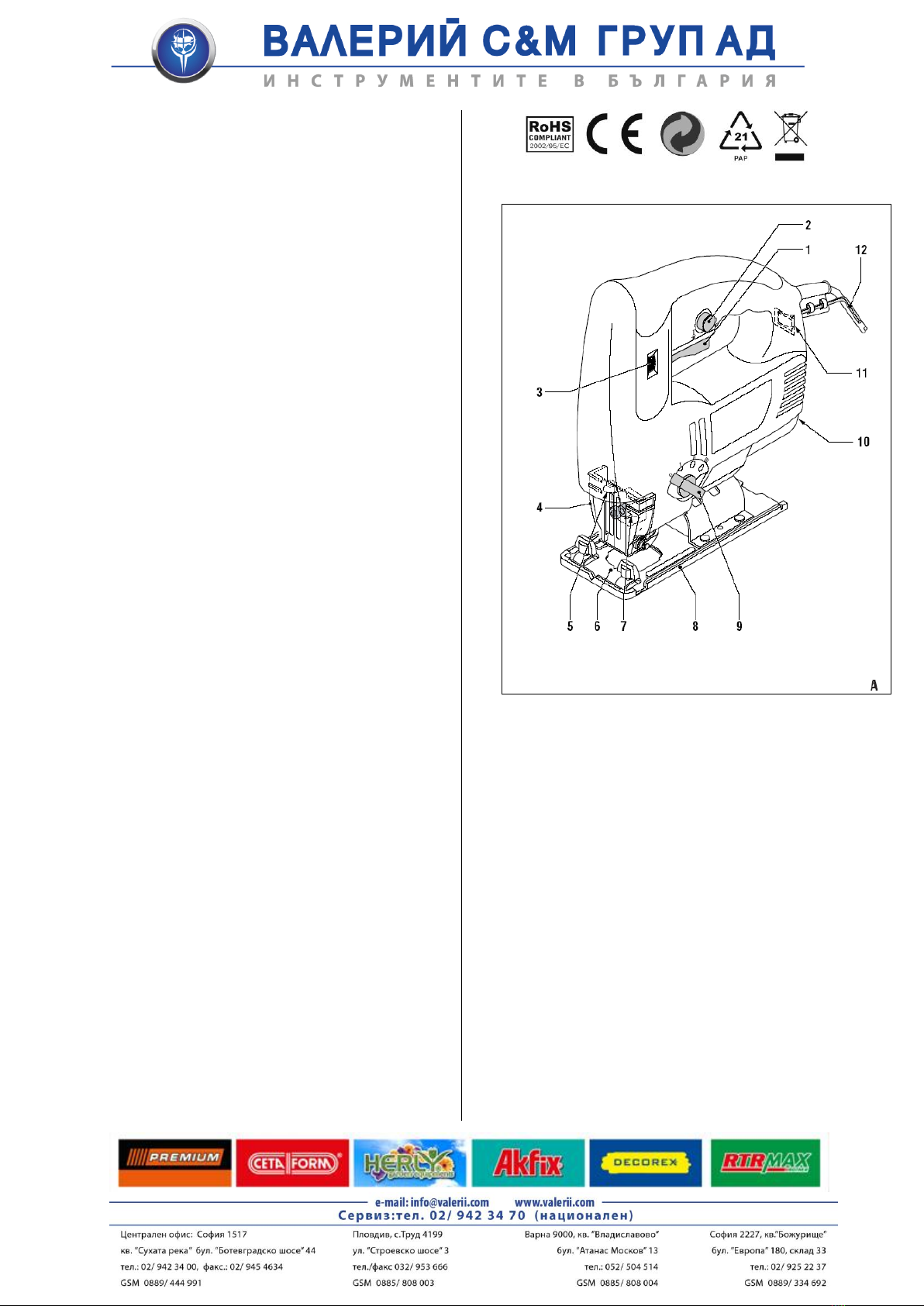
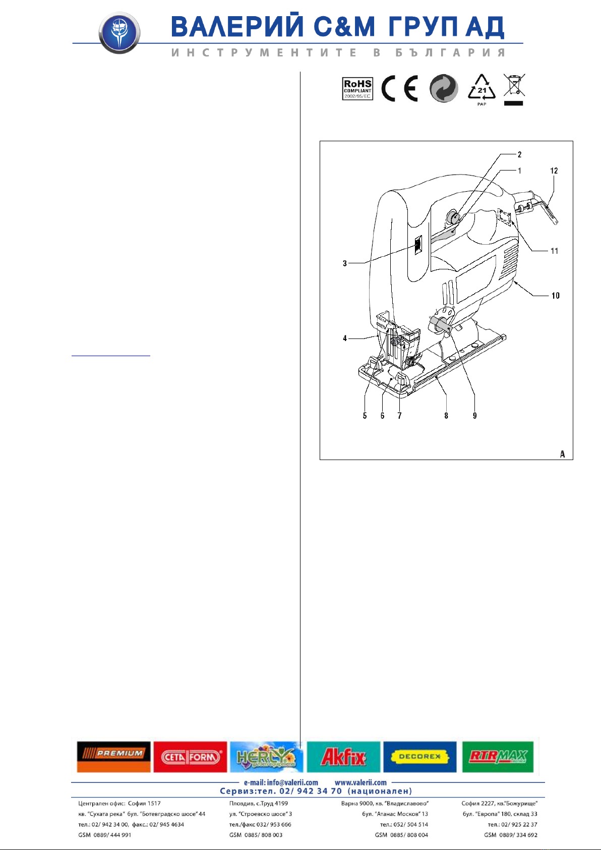
DESCRIPTION (fig. A)
Your pendulum action jigsaw has been
designed for sawing wood, metal and
plastics.
1 On/off switch
2 Lock button
3 Speed adjusting wheel
4 Safety guard
5 Laser
6 Saw marking
7 Saw blade holder
8 Shoe
9 Pendulum action switch
10 Dust extraction connection
11 Laser on/off switch
12 Allen key holder
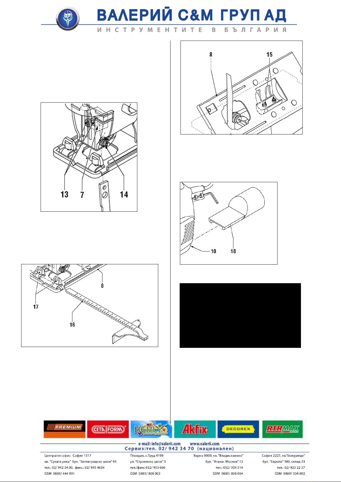
Mounting saw blades (fig. B)
The opening in the saw blade holder (7)
must be clean and free from saw dust.
Loosen the set screws (13).
Slide the saw blade up to the stop in the
saw blade holder (7). Make sure that the
back of the saw blade engages in the slot
of the guide roller (14).
Tighten the set screws (13) firmly.
The set screws (13) may loosen
during use by vibration and damage the saw
blade.
Regularly check that the saw blade is fastened
firmly and if necessary fasten the set screws.
Only carry out this inspection when the machine has
been switched off, the plug has been removed from
the wall socket
and the saw blade has come to a
stand still!
Sharp saw blades produce the best result. Replace
worn saw blades on time by new ones.
Remember that continuous use of worn saw blades
reduces the accuracy of the machine and may lead
to overloading the motor!
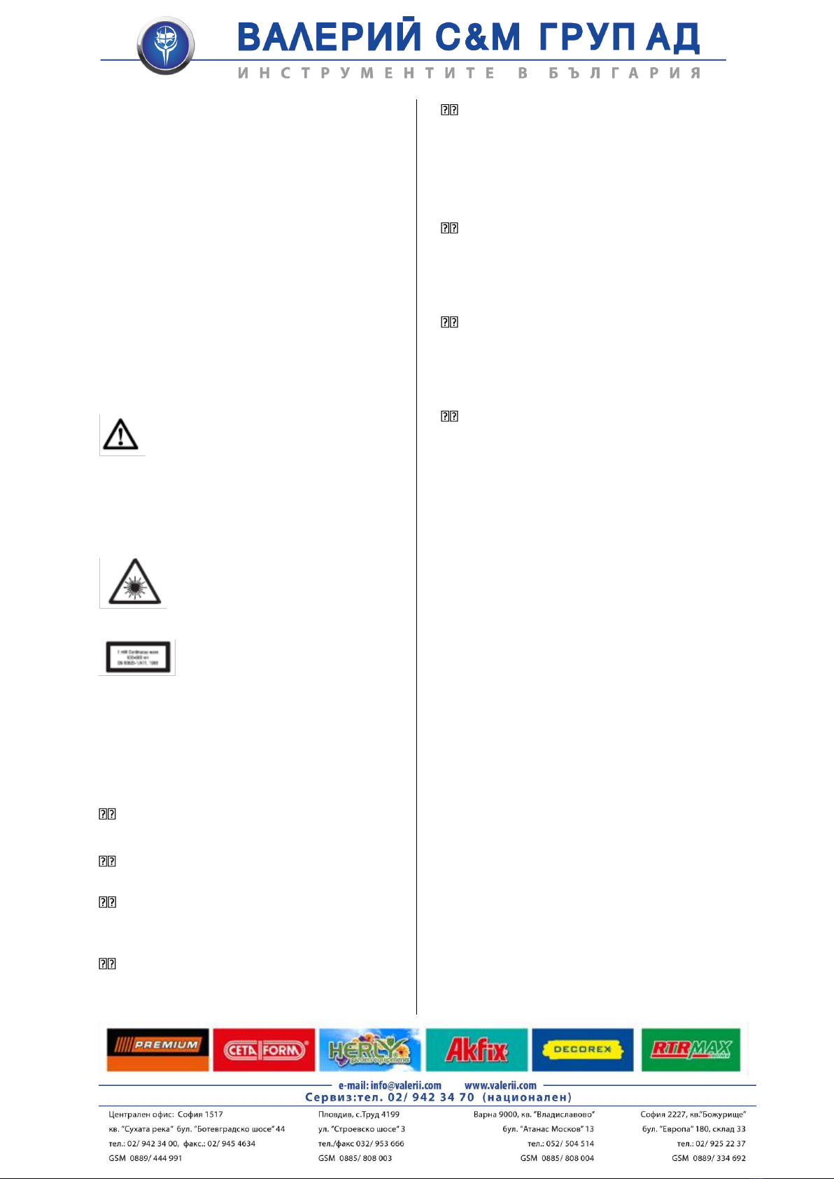
Cutting of mitre angles (fig. C)
The max. mitre angle to the left/right is 45°.
Loosen the set screws (15).
Tilt the shoe (8) to the required mitre angle.
Tighten the set screws (15) firmly.
Mounting the parallel guide (fig. D)
The parallel guide allows sawing parallel to
an edge at a maximum distance of 10 cm.
Insert the parallel guide (16) into the saw
base (8) as shown in the illustration.
Set the parallel guide to the required
distance and tighten the locking bolts (17).
Using the pendulum action switch (fig. A)
The pendulum action switch is used to set
the correct sawing angle for the material.
Turn the switch (9) to the required
pendulum action position. Refer to the
table below for the correct pendulum
action position for different materials.