FrontRow ezRoom ICR-01 Assembly instructions

ICR-01 Smart Receiver
INSTALLER GUIDE

Welcome to FrontRow™– the teacher- and tech-friendly way to improve the learning environment in every classroom.
To make your installation of the FrontRow ICR-01 Smart Receiver as efficient as possible, we recommend that you first
read the section in this guide called Before You Begin, and from there proceed to Steps 2 through 5.
If you follow the steps set out in this Installer Guide and organize everything you need beforehand, you’ll find setting up
your FrontRow ICR-01 Smart Receiver to be quite simple. Of course, if you run into any obstacles, you can always find
contact information for our technical support representatives at www.gofrontrow.com/contact-us.
Thank you for choosing FrontRow! You’re just steps away from a more productive classroom.
You’re About to Make
Learning More Accessible

CONTENTS
Step 1: Before You Begin
Visualize your goal ............................................................................ 1
Get Familiar with input and output ports ......................................................... 2
What do you want to amplify? What do you want to transmit and to what device?....................... 3
Gathering Information ......................................................................... 3
Step 2: Configuration
Connect to your ICR-01 Smart Receiver........................................................... 4
About....................................................................................... 5
Load/Save . . . . . . . . . . . . . . . . . . . . . . . . . . . . . . . . . . . . . . . . . . . . . . . . . . . . . . . . . . . . . . . . . . . . . . . . . . . . . . . . . . . 6
Intercom/PA Audio ............................................................................ 6
System Settings .............................................................................. 7
Beacon / LCD ................................................................................ 9
Network/COM .............................................................................. 11
Command Line .............................................................................. 12
Shortcuts . . . . . . . . . . . . . . . . . . . . . . . . . . . . . . . . . . . . . . . . . . . . . . . . . . . . . . . . . . . . . . . . . . . . . . . . . . . . . . . . . . . 12
Action Creator .............................................................................. 13
Event Creator ............................................................................... 14
Step 3: Physical Installation Prep
Recommended tools and materials ............................................................. 16
General safety precautions .................................................................... 16
Step 4: Plan Your Installation..................................................................... 17
Step 5: Install your Smart Receiver ............................................................... 18
Troubleshooting ................................................................................ 24
Appendix A: Control commands for the Smart Receiver ............................................ 25
Appendix B: Configuration File Settings........................................................... 28
Appendix C: Network Settings ................................................................... 29
Appendix D: Connecting a CB-50 Volume Control to the Smart Receiver Intercom Port ................ 34
Appendix E: Connecting a CB-55 Volume/Pairing Control and Input Wall Plate to the Smart Receiver ... 36

Make sure you’ve got everything you need to install your ICR-01 Smart Receiver. By taking the time to prepare, you’ll
ensure the actual set up is as quick and problem-free as possible.
1. Visualize your goal
Your ICR-01 Smart Receiver can be a component of a Conductor IP-based paging system and / or an ezRoom classroom
AV management system. When your ICR-01 Smart Receiver is part of an ezRoom installation it might look like this:
Step 1: Before you begin
1
The FrontRow ICR-01 Smart Receiver is an amplification and control device that is used in ezRoom®classroom AV manage-
ment systems and in Conductor™paging, bell and intercom systems. This one device amplifies analog audio, encodes/
decodes streaming audio, auto switches between local classroom audio and IP audio, and allows for direct or “pass though”
control of serial devices such as a projector. It resides on an IP network so it can be accessed remotely and securely to
execute its functions.
Network
Switch
5V / 18V
ICR-01
Audio
VGA
HDMI
Audio Extractor
LAN
Audio
HDMI
CAT5
CAT5
CAT5
CAT5
COAX
5V
AV Cable
18AWG
18AWG
Serial
OR
USB Audio
HDMI
OR
CAT5
Relay (CB6000 only)
CAT5
Audio (CB55 only)
Audio
CMBT
ezRoom Installation

2
2. Get Familiar with input and output ports
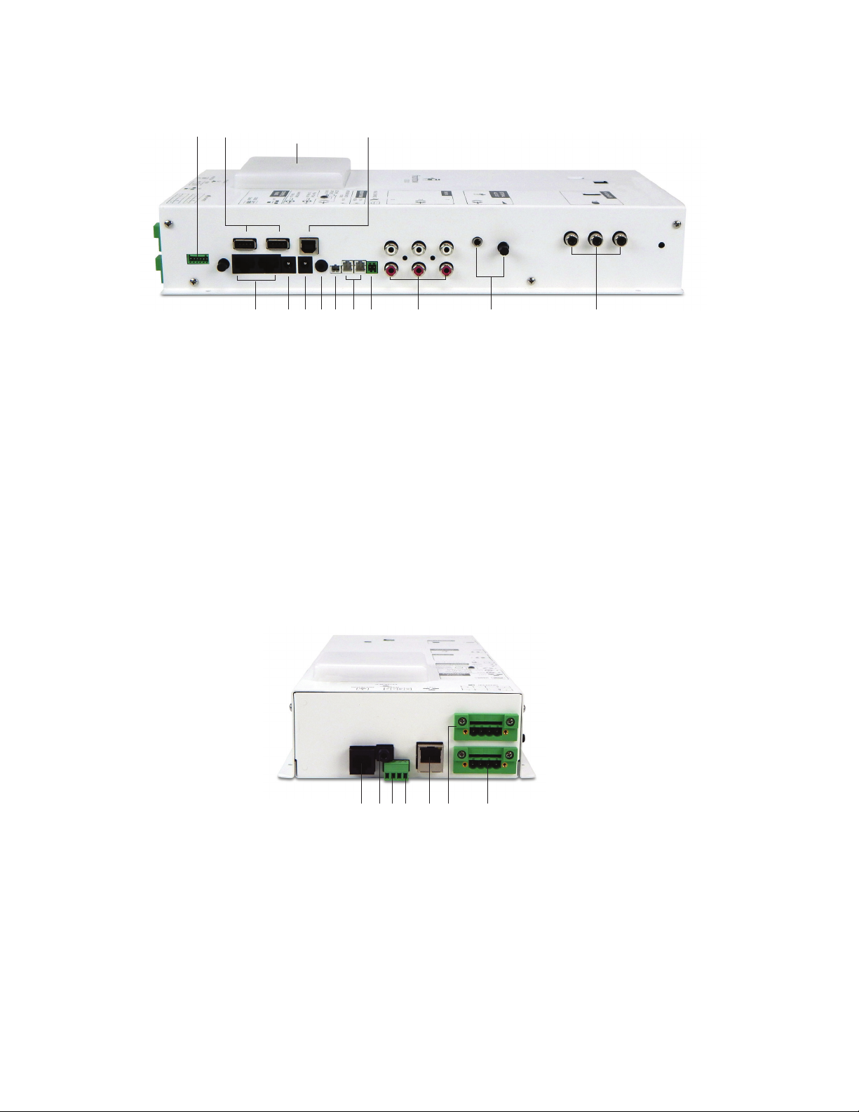
RIGHT SIDE
3 4
5 6 7 8 9 10 11 12 13
1Captive Screw GPO Relay Terminals (6 position)
2Integrated Serial Hub
Two ports for charging or programming microphones (not applicable
with ceiling installation).
3LED Status Indicator
Lights for power and changes color based on status. For example
recording status, incoming audio stream or intercom active.
4Serial Port
Using a USB cable, connect to a computer running FrontRow Teacher
Edition software for control and voice controlled lecture capture
5Control Panel Power
Connect and power a Front Row CB2000 or CB6000 wall control panel.
6Power Connector
7PoE Power Connector
8Line Out for Lecture Capture
9Network Switch Power
10 HDMI Power
Powers optional HDBaseT HDMI receiver and HDMI audio
de-embedder. Can provide power for up to two HDBaseT HDMI
receivers and HDMI switch / audio de-embedder.
11 Page Override Connection
Interface with 20V, 70V or 100V analog paging systems for paging
override.
12 Stereo Inputs for External Audio
Connect other classroom AV equipment such as computer or DVD
player.
13 External ALD Out
Output with gain control for connecting to personal FM assistive
listening devices.
14 Ceiling or wall sensor ports
14
2
1 Intercom Input
Connect the CB75 intercom panel microphone for communication with
front office when push-to-talk is required (can also be used with CB85).
Connect a CB50 volume control with a TB8 cable for basic volume and
mute control. Connect the CMBT Bluetooth audio receiver for wireless
audio streaming and pass-through support for CB85 mic and CB55
volume control.
2 IR Blaster Port
Routes IR control signals from CB2000, CB6000, Encore or Teacher
Edition control panels or Maestro and Conductor platforms
to devices connected via an IR emitter cable.
3Serial Control
Send / receive RS232 commands between connected serial devices
such as projectors and displays.
4 General Purpose Input (GPI)
5Network Connection
Communicates over standard 10/100Mb/s networks (auto sensing)
using either TCP/IP or UDP protocols.
6Speaker Connection
Captive screw terminals for easy speaker connection.
7Optional Speaker Connection (Add-on Expansion)
Captive screw terminals for easy speaker connection. Add up to four
more 8Ωspeakers for use in larger spaces.
BOTTOM
4 5 62 31 7
1

3
3. What do you want to amplify? What do you want to transmit and to what device?
Your ICR-01 Smart Receiver can amplify a variety of audio inputs, and can control devices with serial IR or network interfaces.
Now is the time to plan what you want to do.
Example 1: Typical ezRoom setup with a projector
In the ezRoom Installation diagram on page 1, the ICR-01 Smart Receiver works with other ezRoom components to turn
a projector on and off, handle the transport controls for a Blu-ray player, and control audio volume from the teacher’s
computer, an MP3 player and two FrontRow wireless microphones. If Conductor is being used in the school the ICR-01
Smart Receiver can also amplify PA announcements and provide for two-way intercom calls between the ezRoom
classroom and the office with Conductor.
4. Gathering Information
You will save a lot of time by working with the school to gather information up front.
• Make a list of all rooms to be outfitted and the equipment to be controlled in each one.
• The IT department will provide you with IPv4 addresses for each ICR-01 Smart Receiver and other FrontRow IP address-
able components (these must be static, or fixed, IP addresses), along with other network information, such as the subnet
mask, router IP address and FrontRow server IP address.
• Will the room include voice amplification?
• Will the room be served by a Conductor system for paging? For intercom?
• Will there be an IR-controlled device?
• Will the room controller be a FrontRow CB2000 or CB6000?
• Organize the network information in a spreadsheet such as the one found at
http://gofrontrow.com/guides-resources/room-control-project-planning-template.xls

Your ICR-01 Smart Receiver has several parameters that can be configured to tell it how to communicate with other devices in
an ezRoom or Conductor installation. While each installation is different most of the default parameters will be appropriate.
1. Connect to your ICR-01 Smart Receiver
• Connect your laptop computer’s LAN port to the ICR-01 LAN port with a CAT-5, or network, cable.
• Change the IPv4 address on your laptop to static address 192.168.1.100. See Appendix B for instructions.
• Open a web browser on your laptop and in the URL field type the IPv4 address 192.168.1.103 and press enter. This is
the default static IP address of the ICR-01 and will likely be changed when you configure it per the school’s IP
addressing scheme.
• You will be connected to your ICR-01 Smart Receiver and see a screen like this:
4
Step 2: Configuration
ICR-01 Bottom

5
2. About
Device Information
The name you choose should contain meaningful information, such as the classroom number, so that a person accessing the
device remotely will have appropriate context. Also on this screen you can see the device MAC address and firmware version.
Password
If the project requires it you can password-protect the ICR-01 Smart Receiver configuration screens by setting a password. If
setting a password for the first time, the “old password” is calypso. Choose a new one based on the school’s guidelines and
record the information. The username is always admin.
Audio Subsystem Information
Displays information about the audio subsystem including serial number and firmware version.

6
4. Intercom / PA Audio
These settings are for use when installed with the Conductor IP-based Paging, Intercom and Bell system or with a 29V, 70V, or
100V analog paging system.
Incoming Audio
The PA volume is the volume of incoming audio from Conductor (pages, bells and intercom) and does not affect the volume
of the local (in room) audio. PA Release is the amount of time it takes for the local (in room) audio to return to normal volume
after an incoming audio stream from Conductor.
Outgoing Audio (talk-back)
Gain setting for the audio sent back to the front office from the in-room intercom microphone, i.e. the wall (CB75) or ceiling
(CB85) unit. The gain setting for the pendant microphone when used as the intercom microphone is fixed.
Push to Talk Mode
When used with a CB75 push-to-talk microphone, the push button can be configured in one of three ways:
• Disabled - audio from the in-room microphone can be heard in the front office with no action from the user in the room.
• After push - audio from the in-room microphone can be heard in the front office with no action from the user in the room
until the button is pushed. Thereafter, the user must push the button in the room to activate the microphone.
• Always - audio from the in-room microphone will not be heard until and unless the user in the room is pushing the button.
Analog Page Override
For use with 25V, 70V and 100V analog paging systems. The ICR-01 Smart Receiver will mute all audio in the room when an
announcement is made over the facility’s paging system. Analog page override requires a connection to the facility’s PA
system. For information about connecting the page override function to the PA system, please see page 20.
Attenuation. Set the attenuation level applied to the audio in the classroom when an announcement is made over the school
PA system. The default setting (10) mutes the in-room audio when an announcement is made.
3. Load/Save
The set of configuration parameters created in this interface can be saved in a file for use with other ICR-01 Smart Receivers.
In this section you would “save” a configuration file or “load” a file from a location on your computer. Some of the parameters
would still need to be changed (e.g., the IP address).
Load Configuration
Browse for a previously saved ICR-01 Smart Receiver configuration file an load it on this device.
NOTE: Configuration files created on FrontRow devices (e.g. Juno Connect, CM3000) are not compatible between device types.
Save Configuration
Save the configuration file from this device for use on other ICR-01 Smart receivers.
NOTE: Configuration files created on FrontRow devices (e.g. Juno Connect, CM3000) are not compatible between device types.

7
PA Release. Sets how quickly the in-room audio returns to its previous level after the announcement is complete
Sensitivity. Sets how sensitive the trigger will be for muting the system. The lower the setting, the lower the sensitivity will be.
While music is playing in the classroom, make a long announcement over the PA system. Adjust the sensitivity control until you
just mute the music. When the announcement stops, the music should return to full volume.
4. System Settings
These settings affect the local audio in the room (microphones and auxiliary sources) and other device settings
Volume
Adjusts the master volume of all the inputs together (microphones and auxiliary sources). Individual volumes can be adjusted
based on relative volume of devices or microphones. Note that this is not a permanent setting — it will change when the
volume is changed in other ways, e.g., using Teacher Edition or Encore software, via voice commands, or via control devices
such as the CB6000, or even the knob on a CB75.
Microphone Volume
Each microphone in the room can have a different volume setting. For example, student microphones can be set at a lower
volume than the teacher’s microphone. Adjusting the master volume will keep the same relative difference between the
microphones.
Aux Input Volume
Adjusts the individual volumes of the auxiliary inputs. Each input can have a different volume setting. For example, a DVD
player can be set at higher volume than the teacher’s computer. Adjusting the master volume will keep the same relative
difference between the inputs.
OptiVoice
OptiVoice is a tool that strengthens consonant sounds critical to conveying meaning in speech. For low background noise
environments and for a more natural reproduction of voice, use the low setting. For environments with higher background
noise that can mask consonant sounds, use the mid or high setting.
PrioriTeach
Enable this setting to give the teacher microphone priority over all other in-room audio.

8
Command Channel
Set the channel (A or B) for which channel the teacher mic is using as the command channel for voice commands.
Equalizer
Control individual aspects of the sound from your audio devices such as the bass, middle and treble frequencies.
Microphone Button Mode
The Teacher microphone button can be configured to trigger any defined event or to control the system with voice commands.
If using to trigger an event, choose Mic button press as the Trigger when defining an event. For voice control, choose the
triggers in quotes (e.g. “Power Up”, “Freeze screen”, etc.) when defining the events (for more information on defining events,
see section 8 - Event Creator).
Beacon Brightness
The Beacon indicator light can be adjusted for how bright it will be either during normal operation or while displaying a status
(active intercom, announcement, recording, etc.) or alert feedback.

5. Beacon / LCD
Overview
This page is where you set the color and behavior for the device’s Beacon, as well as any tone associated with a given alert
state.
Select a primary color, Light Off, or Do Nothing for each function. Light Off with turn the beacon off when the function is
active, whereas Do Nothing will leave the beacon unchanged from its current color. In the Pattern column, select Solid,
Flashing, or a second color that will alternate with the primary color. A high powered strobe light is also available on the
beacon and can be combined with the colors for security alerts.
IMPORTANT: The ALERT FUNCTIONS should be configured in accordance with the school’s Emergency Preparedness Plan.
Download and review the Guidelines for a Successful Conductor Deployment for more information.
System Functions
System On: Displayed when the system is powered on and an audio signal is present (after 30 minutes of no activity the
Beacon will turn off).
Backup PoE Power: The primary power source for the device is no longer available and the unit has switched to Power over
Ethernet (usually due to a power outage).
Voice Command: When holding down the mic button, lets teachers know that the system is ready to receive the voice
command. Only available if the system has been set to Voice command mode (see System Settings page).
Recording: Active when a lesson capture has been initiated using Teacher Edition software. Requires a USB connection to the
computer. Helps teachers understand that a recording is in progress.
Recording Paused: When the lesson capture is paused, the Beacon will show this state.
Intercom: Lets teachers know that a two-way intercom call is active between the classroom and the office, muting all other
audio sources. (Used with Conductor)
Paging: Lets teachers know that a one-way PA announcement is being played through the system, muting all other audio
sources. (Used with Conductor)
9

Alert Functions
Alert Delivered: When a Conductor HTTP alert call is sent, usually by pressing a button in the classroom (on the wall, in
software, or using the mic), this automatically confirms to teachers that the alert was delivered to the Conductor Notifier over
the network.
Alert Acknowledged: When a person presses the “Acknowledge” button in the Conductor Notifier, this state is activated on
the device that sent the alert (or is acting as the alert proxy). By default, this function returns to the normal System On state
after 5 minutes (not user changeable). In this way, a teacher can see that a person has seen their alert.
Campus Attention: When an alert is triggered from a classroom, it may be useful to let other classrooms know that this
has occurred, so that they can be better prepared for instructions. By sending a command to the broadcast IP address of
the subnet that Conductor is on, all supported devices will activate this function for a period of 4 seconds. To enable this to
happen automatically, add a network command action to the event that makes the Conductor HTTP alert call. For example:
#NET[F2, I192.168.1.255, P7262, ‘#PAS[“CAS”];’];
To make this a manual function that is initiated by the office manager or other personnel, create a button in Conductor which
sends the #PAS[‘CAS’]; command to the broadcast IP address (e.g., 192.168.1.255) of the subnet that Conductor is on.
Priority Alerts: As schools may want to have different colors and behavior for different types of situations, there are 5
different Priority Alert modes. Typically these will be programmed into various alert buttons in Conductor, using a control
action in a trigger script. The commands to use in the control actions are shown below. For all FrontRow devices to receive
the command at once, set the control action to be sent to the broadcast IP address of the subnet Conductor is on (e.g.,
192.168.1.255).
Testing
Press the “Test”button to see a 5 second example of your alert settings (note that the tone will not be played). This test uses
the values currently selected on the web page, not the saved values.
You can also use the Command Line page to test your alert settings. The commands are shown below in order of priority. For
example, a Priority Alert will override an Alert Delivered function, changing the state of the device’s Beacon. All Priority Alerts
have the same priority and the device will display the most recent one received.
Campus Attention #PAS[‘CAS’];
Alert Delivered #PAS[‘ADS’];
Alert Acknowledged #PAS[‘AAS’];
Priority Alert, mode 1 #PAS[‘HPS’]; or #PAS[‘HPS’,M1];
Priority Alert, mode 2 #PAS[‘HPS’,M2];
Priority Alert, mode 3 #PAS[‘HPS’,M3];
Priority Alert, mode 4 #PAS[‘HPS’,M4];
Priority Alert, mode 5 #PAS[‘HPS’,M5];
Alert (any type) off #PAS[‘OFF’];
10
NOTE: The FrontRow alert notification feature is not intended to nor can it prevent emergencies. FrontRow Calypso LLC, its agents, employ-
ees, subsidiaries, affiliates and parent companies are not responsible for individual applications of the alert notification feature or related
equipment, and shall be exempt from liability for any loss, damage, injury or other consequence arising directly or indirectly from said
application. In the event of misuse or malfunction of the equipment or any of its components or features, FrontRow Calypso LLC, its agents,
employees, subsidiaries, affiliates or parent companies shall be exempt from liability for any loss, damage, injury or other consequence
arising directly or indirectly therefrom.

11
6. Network / COM
Network Configuration
Automatic IP Configuration (DHCP) Use this setting to have this device request an IP address from a DHCP server; this
should be enabled only if the IT department has a DHCP server online and has set up static (fixed) IP address reservations
for FrontRow devices; otherwise manually enter the IP address reserved for the device in the IP Address field. It is highly
recommended that static IP addresses be used.
IP Address The field displays and also enables entering (changing) the IP address for the device; while the default address is
192.168.1.103. You must use the address provided by the IT department and ensure that each device has a unique address.
IP Subnet Mask Provided by the IT department; if used as part of a Conductor system, the subnet mask must be
255.255.255.0.
Router IP Address Required when this device is in a network in which router switches determine connectivity across subnets.
Provided by the IT department.
Primary NameServer IP Address Optionally provided by the IT department. Rarely used with this device, only enter an IP
address here if specifically requested by the IT department.
Secondary NameServer IP Optionally provided by the IT department. Only enter an IP address here if specifically requested
by the IT department.
Network ports (CNAP, HICP) Under rare conditions, it may be necessary to change the network communication ports used
by other devices and software to communicate with this device. If a such a change is necessary, please direct your browser to
the /cfg/advanced.htm page for this device and refer to the help there.
Serial Port Configuration
Baud Rate Specifies the data speed at which this device should communicate with the attached serial device; while 9600 and
19200 are typical for projectors, data speeds vary by manufacturer.
Stop Bits Specified by the manufacturer of the connected serial device, but is typically 1.
Parity Specified by the manufacturer but is typically None.

12
7. Command Line
Enter Command
Use this section to test commands sent to a device to verify that it performs the action desired. Use the drop down list to
select examples of FrontRow command protocols.
8. Shortcuts
Shortcuts
Shortcuts are name substitutions. Defining Shortcuts makes deployment of multiple FrontRow devices of the same type
easier. Use Shortcuts in defining actions that represent the IP addresses of the devices you’ll control. This means that your
configuration file can be written as a template with IP addresses explicitly defined in only one place (the Shortcut), needing to
be changed only once rather than repeatedly throughout your Actions. This saves a tremendous amount of labor as you re-use
the configuration file to control new devices from room to room.

13
9. Action Creator
Actions are specific instructions that are sent to specific devices (e.g. to turn a projector on or change inputs on a projector).
Once defined, you will link them to various Events which can be triggered in a variety of ways, including voice commands.
To create an Action:
1. Click New
2. Name the Action
3. Enter the action string or Command
Actions can be created using two methods:
1. Using a wizard
• Select an Action Type using the drop-down list
• Enter the syntax necessary to build the specific action
2. Using a Template
• Select an Template using the drop-down list
• Edit the syntax necessary to build the specific action (e.g. IP address)

14
10. Event Creator
With your collection of discrete Actions defined, you can now specify what Events will cause one or more of those Actions to
be executed. Events can be triggered in a variety of ways, via Voice Command, Encore and Teacher Edition software, FrontRow
Control panels, a FrontRow push button (CB75 microphone or CB50) or from a non-FrontRow GPI trigger.
To create an Event:
1. Click New
2. Name the Event
3. Choose a Trigger. A trigger is a way to invoke the event you are building.
Triggers can be physical devices such as a non-FrontRow push button connected to the GPI (GPI open / close), or a
FrontRow device connected to the RJ45 intercom jack (Wall knob press, release, turn right, or turn left). A voice command
can also be a trigger. Voice commands are the words in quotes (“Power up”, “Shut down”, etc.). The Mic button press
trigger is on the Teacher worn microphone. A press and hold will trigger the defined event. In order for this functionality
to work, the microphone must be programmed for trigger mode. This is done via the System Settings page. A system
with the trigger function enabled, will have the voice command function disabled. You can have multiple Events with the
same input trigger. When that defined trigger is detected by the device all the matching Events will be executed in no
particular order. For each such Event, the Actions for the Event will execute according to that Event’s mode setting (see
below); however, Actions for different Events may be intermingled with each other. If you care about the order in which
Actions happen, put them all in a single Event and set the mode to Each (in order).
4. Choose a Mode. The mode determines how and in what order each action in the event will be invoked.
All (in parallel): All actions for the event will be executed but in no particular order. When order does not matter but you
want things to happen as quickly as possible, this is the recommended choice.
Each (in order): Actions for the event will be executed in the order listed. This is useful when the order matters to you; for
example, turning off a projector before retracting a projector screen. To change the order of the actions in the event, drag
actions up or down with the three lines next to the action name.
One per call (in sequence): The actions will be treated as a loop, executing the next Action in the series each time the
Event is initiated (e.g., with 2 actions: Action 1 on the first button press, Action 2 on the second button press, Action 1 on
the third button press, etc.). This is useful for toggle functions like power or mute.

15
5. Add Actions
Actions can be added and will be invoked according to the mode chosen in step 4. To add actions, select them and click
Add Selected. Actions can be reordered by clicking and dragging the lines to the left of the action name in the Current
Action List.

16
Nearly everything you need to install your FrontRow Smart Receiver is included with it, or in the shipping box of the plenum or
wall enclosure containing the Smart Receiver. However, you will need some basic tools and materials, depending on how your
classroom is built.
Recommended tools and materials
• Plastic cable (zip) ties
• Cable tacks/staples
• Drill (or hammer drill for concrete walls)
• Drill bits (masonry bits for concrete walls)
• Slotted screwdriver
• Level or ruler/tape measure
• Crimp pliers or scissors
• Ladder
• Staple gun
• Safety goggles
General safety precautions
• Do not install or use the Smart Receiver near water or a heat source
• Clean only with a dry cloth
• Protect all cables from wear and damage from doors or other hazards
• Use only accessories specified by FrontRow
• Refer servicing to qualified service personnel
• Wear safety goggles when using power tools
Step 3: Physical Installation Prep

17
Estimated time for this step: 3 – 10 minutes
Now it’s time to decide where you’ll place the Smart Receiver. If it is part of an ezRoom configuration:
* Be sure to refer to the Installer Guides for the various ezRoom components for best results.
• Locate the Smart Receiver (and optional plenum enclosure) near a power supply and the classroom’s network drop.
• Typical maximum cable lengths are 330’ for CAT 5 network cable runs, 50’ for RS232, and 50’ for IR. Typical maximum
lengths for speaker cables are 50’ though please refer to the applicable FrontRow product documentation for specific
requirements. For AV plates please refer to the specific AV plate documentation.
Step 4: Plan your installation
Student desks
Teacher’s desk,
computer and
document camera
Blu-ray Player
White board/
projector screen
Top view of an example classroom
Windows
Other manuals for ezRoom ICR-01
1
Table of contents
Other FrontRow Educational Equipment manuals
Popular Educational Equipment manuals by other brands

Nasco Healthcare
Nasco Healthcare CPR+ PROMPT user guide

Enabling Devices
Enabling Devices Totally Tactile Communicator user guide

laerdal
laerdal SimNewB user guide

Enabling Devices
Enabling Devices 2251 user guide

TruCorp
TruCorp AirSim Bronchi user manual

Aircatglobal
Aircatglobal Virtual Fly SOLO GA user manual

TruCorp
TruCorp AirSim Difficult Airway user manual

RoboMaster
RoboMaster S1 Education Expansion Set Core quick start guide

LeapFrog
LeapFrog Leapster 2 Parent guide & instructions

ADEEPT
ADEEPT Super Starter manual

Keyestudio
Keyestudio Basic Starter Kit Series manual

Pitsco Education
Pitsco Education Wheel Lathe user guide