INSTALLATION AND MAINTENANCE MANUAL
TRANSLATION OF THE
ORIGINAL DOCUMENT
For additional copies visit:
www.frost-trol.com
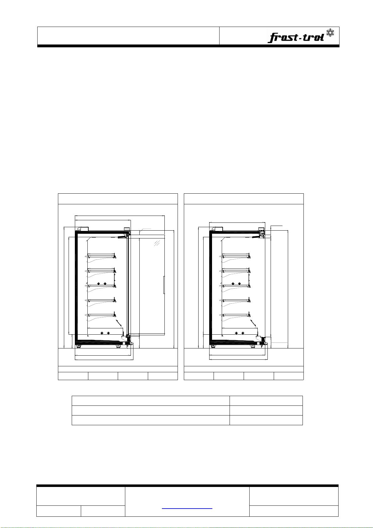
GREGAL
SOLID LINES
D008270 Versión: 2 -1-
Index
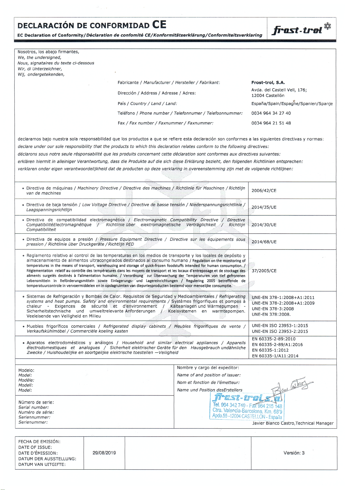
EEC DECLARATION OF CONFORMIT ................................................................ 3
SAFET ADVICE ............................................................................................. 4
1.
GENERAL INFORMATION ................................................................... 7
1.1.
DESCRIPTION OF REFRIGERATED DISPLA CABINET ............................ 8
1.2.
GENERAL CHARACTERISTICS ............................................................. 8
1.3.
SHOP CONDITIONS .......................................................................... 9
1.4.
OPERATING THE COOLING S STEM .................................................... 9
1.5.
RECEIPT OF REFRIGERATED CABINET ................................................. 9
1.6.
DAMAGE SUSTAINED IN TRANSIT ...................................................... 9
1.7.
TECHNICAL ASSISTANCE................................................................... 9
1.8.
STORAGE .......................................................................................10
2.
INTALLATION OF REFRIGERATED DISPLA CABINET ............................10
2.1.
CABINET LOCATION .........................................................................10
2.2.
UPACKING ......................................................................................11
2.3.
LEVELLING .....................................................................................11
2.4.
INSTALLATING THE DRAINAGE SISTEM ..............................................11
2.5.
ASSEMBL ......................................................................................13
2.6.
REFRIGERATING S STEM CONNECTION .............................................18
2.7.
INSTALLATION’S DR ING .................................................................18
2.8.
THERMOSTATIC VALVE CONTROL ......................................................18
2.9.
ELECTRICAL CONNECTION ...............................................................19
2.10.
DOORS INTALLATION ......................................................................20
2.11.
CLEANING ......................................................................................20
3.
OPERATION ....................................................................................21
3.1.
INITIAL START-UP ...........................................................................21
3.2.
PRODUCT LOADING .........................................................................21
4.
MAINTENANCE AND CLEANING .........................................................22
4.1.
GENERIC CLEANING ROUTINE ...........................................................23
4.2.
INTERNAL CLEANING PROCEDURE .....................................................23
4.3.
DOORS MAINTENANCE .....................................................................24
4.4.
REPLACING LAMPS ..........................................................................24
5.
SPARE PARTS REQUEST ...................................................................25
6.
FAULTS AND REPAIRS ......................................................................26
6.1.
MALFUNCTIONS ..............................................................................26
6.1.1.
THE UNIT DOESN’T START UP OR IT STOPS: ......................................26
6.1.2.
THE UNIT DOES NOT GET COLD ENOUGH: .........................................26