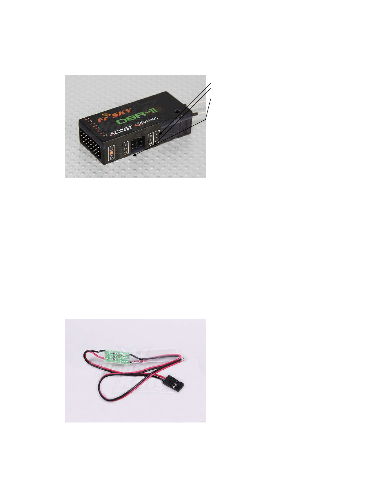
3.2.2 FBVS01 external battery level telemetry sensor
This sensor has 3 voltage dividers - soldering
pins: 1S (1-2 cell LiPO max. Divider for FLD-
02 = 2), 2S (1-4 cell LiPO max. Divider = 4),
3S (1-6 cell LiPO max. Divider = 6).
Initially, red wire that goes to the battery is soldered to 3S pin on board, i.e. – any LiPO battery from
1 to 6 cells. In case of using, for example, up to 4 cells – you should re-solder it to 2S pin in order to
get more accurate voltage metering by the sensor.
*from now on – we would use 3-cell LiPO (11.1V) as an example….
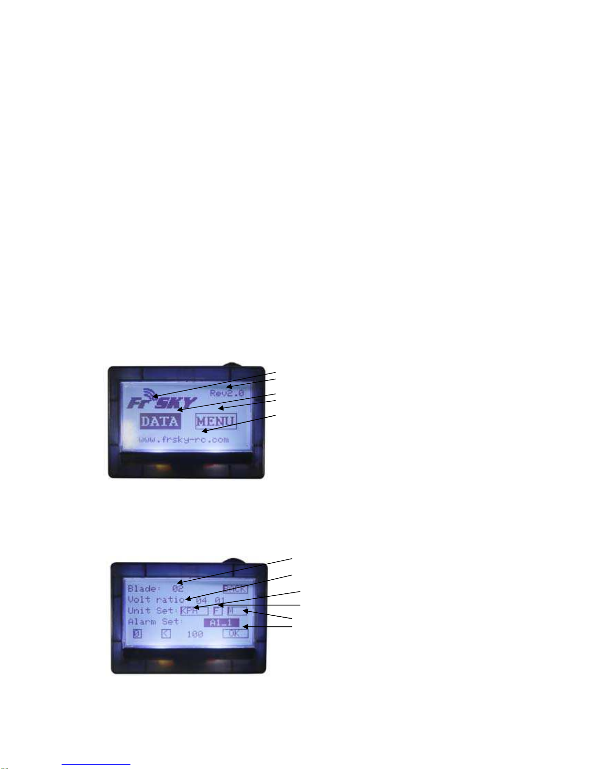
After re-soldering red wire to 2S pin, connecting this wire to the battery, and connecting FBVS01
sensor to RX A2 telemetry port – you would have to setup the appropriate voltage divider for our
specific soldering type in order to have the appropriate readings in A2 cell (right) of “A1 & A2
Voltage” section (look at section 3.3.1 of this manual) of “DATA Screen 1”. To do this – go to
“MENU” Screen (section 3.2 of this manual) and set the appropriate divider value for A2 in “Volt
Ratio” section (as it is stated above, near the picture with soldering pins layout), i.e. 4 (for our
soldering type 2S and 3-cell LiPO battery).
*note: if you are using only 1 battery in you RC-model (without separate battery for electronics) –
you should NOT use|connect black (Ground) wire of voltage sensor. Just do NOT connect it. Throw
it away or cut it, or just forget it. The only cable that should be connected to RX and battery – red (+).
In case of 1 battery, Ground is already supplied to the RX from ESC. If you would supply another
one Ground through sensor to RX telemetry port – you would have Ground-loop because electrons
would follow the lowest-resistance route omitting long RX-electronic circuit. It would eventually result
into electronics (gyro, servo, etc) short-time or permanent failure.
In case if you use 2 separate batteries – 1 for electronics and another one to power-up the motor
and you are connecting sensor to motor-battery – you can use + and – without any ground-loop.
How to setup an alarm for sensor readings (look at section 3.3.2 of this manual)
3.3 DATA Screen:
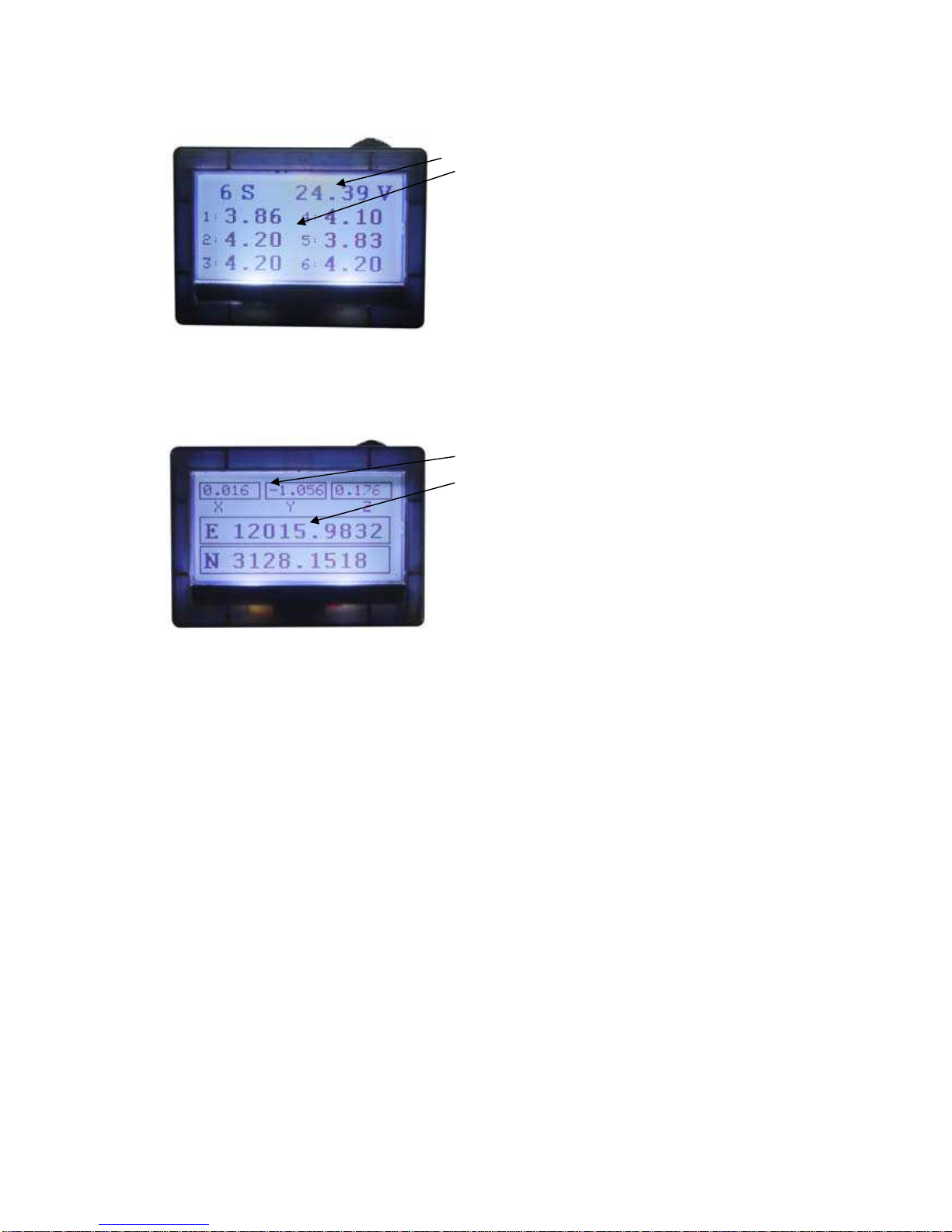
3.3.1. Screen-1
GMT (h/m/s)
Fuel level
A1 & A2 Voltage ( readings from А1 and А2 RX ports)
Temperature 1 & 2
Rx RSSI (level of RX signal) & Tx RSSI (level of TX signal)
*note: RX and TX signal level is shown without any sensors attached to RX. This is default built-in
function. This function also allows alarms to be set (look at section 3.3.3 of this manual)