FrSky Dragon Fire Series User manual

(86)510-85187718
www.frsky-rc.com.cn
Dragon Fire Series
VLQ-2500T (with intercom)
4-channel full function
video transmission system
User Manual
F3, Building C, No.3 Yuanxi
Road, Wuxi, 214000

Add: F-4,Building C, Zhongxiu Technology Park, No.3 Yuanxi Road, Wuxi, 214125, Jiangsu, China Technical Support: [email protected]
Instruction Manual for
Dragon Fire Series VLQ-2500T (with intercom)
4-channel full function video transmission system
Instruction Manual for Dragon Fire Series VLQ-2500T (with intercom)
4-channel full function video transmission system
01
Contents
1. About this user manual + Product Overview + Product List ------------------- 01
2. Product Features ------------------------------------------------------------------------- 01
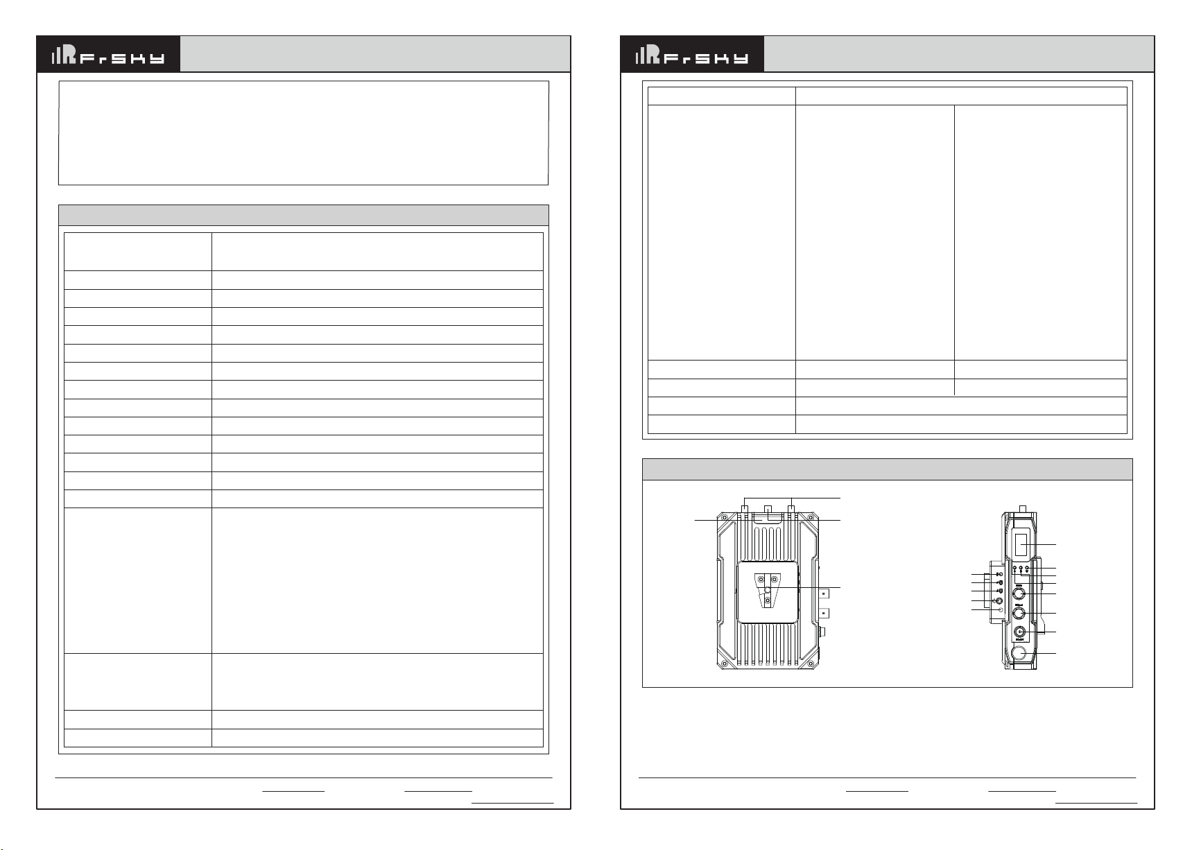
3. Product Specification -------------------------------------------------------------------- 02
4. Transmitter three side diagram and button definition --------------------------- 03
5. Receiver three side diagram and button definition ------------------------------- 04
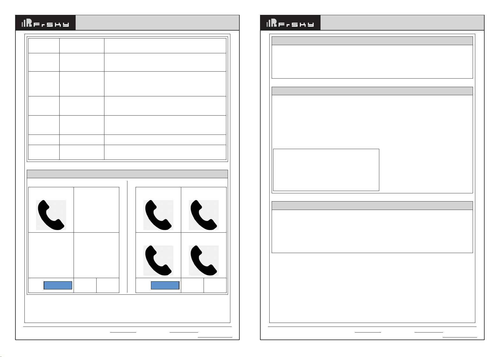
6. Intercom system host three side diagram and button definition -------------- 05
Intercom system host operations ----------------------------------------------------- 05
Intercom system host OLED description ------------------------------------------- 06
How to switch the intercom system frequency and Group ID ----------------- 07
Menu setting description ---------------------------------------------------------------- 07
Intercom system bind operation ------------------------------------------------------ 07
7. Transmitter and receiver initial information description ------------------------ 08
Transmitter initial information definition -------------------------------------------- 08
Receiver initial information definition ------------------------------------------------ 08
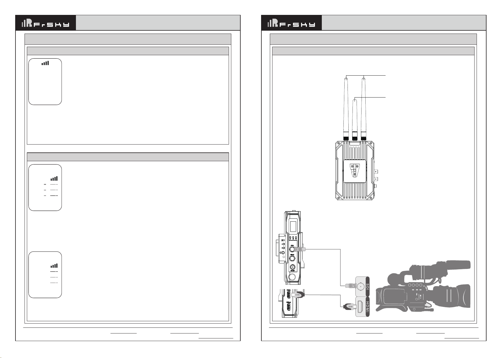
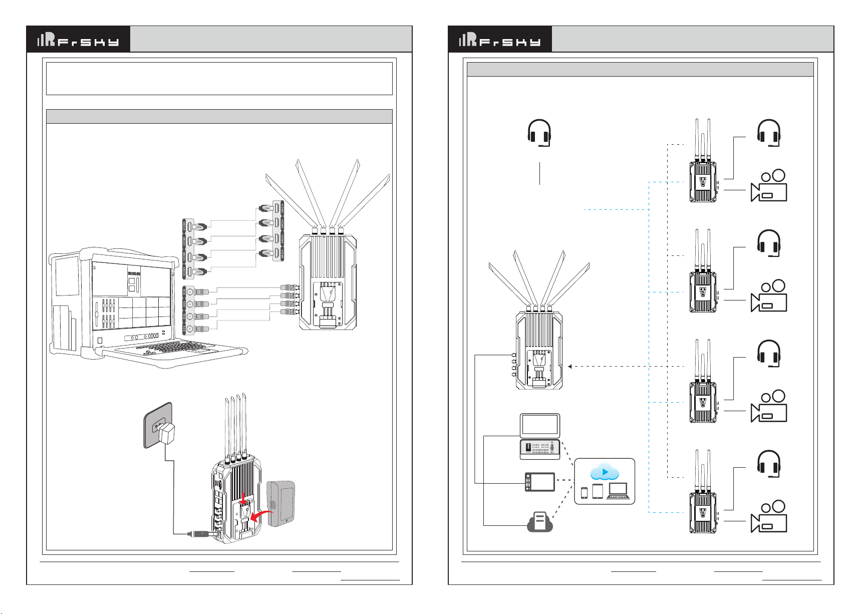
8. Installation method and instructions for usage ------------------------------------ 09
Transmitter --------------------------------------------------------------------------------- 09
Receiver ------------------------------------------------------------------------------------ 10
Intercom system host ------------------------------------------------------------------- 11
9. How to bind, how to switch frequency ----------------------------------------------- 12
How to bind -------------------------------------------------------------------------------- 12
How to switch frequency ---------------------------------------------------------------- 13
10. How to switch video quality ----------------------------------------------------------- 14
11. How to switch RTSP, RTSP steaming instructions ---------------------------- 14
12. About TALLY ---------------------------------------------------------------------------- 15
13. RS232/RS422 transparent transmission and PTZ control function -------- 16
14. How to switch the 422 serial port baud rate to adapt to different PTZ control
commands -------------------------------------------------------------------------------- 16
15. Troubleshooting ------------------------------------------------------------------------- 16
16. Attentions --------------------------------------------------------------------------------- 17
About this user manual
This user manual introduces VLQ-2500T 4-channel full function wireless video transmission specifications、
instructions、attentions and troubleshooting.
Before using this product, please carefully read this manual. If you have any doubts or troubles while using this
product, please contact us or our dealers.
Product Overview
VLQ-2500T is a innovative full HD wireless video transmission system. It includes four transmitters and one
receiver, built in 2.4G intercom system. The four channels video transmission share one RF channel, the best
video resolution supports 1080P/60HZ. This product is based on 5G wireless network technology for
transmission. It has advanced 4x4 MIMO technology, adopted H.265 encoding and decoding technology for
video processing, make the video quality clearer and the latency lower. This product also integrates independent
2.4G intercom system. This system has clear voice, easy to carry. It is a good partner of the team director for live
broadcasting.
Product List
• Receiver X1
• Transmitter X4
• Intercom system hostX1
• Receiver power adapter X1
1. About this user manual + Product Overview + Product List
• Intercom system
power adapter X1
• 5.8G antenna X14
• 2.4G antenna X6
• Headset X5
• Network cable X4
• 422 to network cable X4
(optional)
• D-Tap to 2-pin LEMO cable X4
• Gooseneck microphone X1
• Double ball head magic arm X4
• SDI cable X8
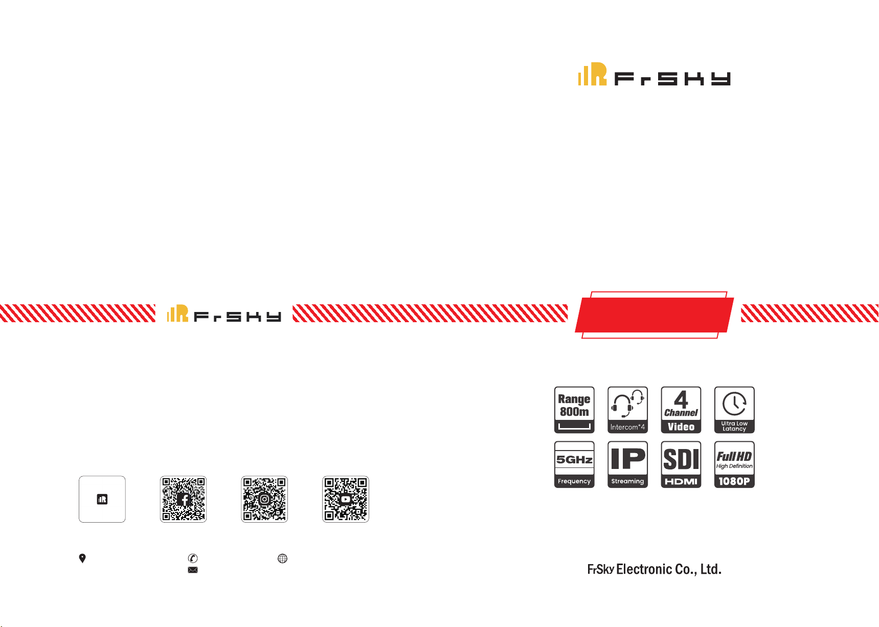
■ High quality and low latency
This product supports HD-SDI&3G-SDI input and output, supports HDMI Full HD input and output, the best
resolution is 1080P/60HZ.
It adopts H.265 encoding and decoding technology with high compression rate and high video quality, the
latency as low as 70ms.
■ Optional video quality:
3 different video quality to select, easy to deal with bad wireless environment.
■ Four transmitters and one receiver share one RF channel
This product supports four channels of video signal transmit at the same time, and the best video resolution of
each channel can reach 1080P/60HZ. Four channels of video signal share one RF channel, which improves
anti-interference ability, saves RF frequency resources, and provides great convenience for users with multiple
camera.
■ 4X4 MIMO
Combining 4x4 MIMO technology, this product has advantages over other WIFI products on the market in
regards to transmission distance and video bitrate. Beamforming technology makes wireless signal more
concentrated and stronger in the direction of transmission to reception, so that the wireless signal can transmit
further, more anti-interference, more stable.
■ RS422,RS232 transparent transmission
This product supports RS422, RS232 transparent transmission, which is convenient for the device connected
to receiver to transmit control commands to camera, such as the pan-tilt-zoom(PTZ) camera.
■ Support point-to-point and RTSP streaming mode
This product supports both point-to-point and RTSP streaming mode. In point-to-point mode, the product
supports four transmit one receive and the video output port is HDMI or SDI. In RTSP streaming mode, the
product supports four transmit one receive and four transmit multiple receive, and the video stream port is RJ45
network port. There are more choices for different applications.
2. Product Features

Add: F-4,Building C, Zhongxiu Technology Park, No.3 Yuanxi Road, Wuxi, 214125, Jiangsu, China Technical Support: [email protected]
Instruction Manual for Dragon Fire Series VLQ-2500T (with intercom)
4-channel full function video transmission system
Instruction Manual for Dragon Fire Series VLQ-2500T (with intercom)
4-channel full function video transmission system
0302
■ Support intercom
Built-in independent 2.4G intercom module, makes sure the cameramen and director can still get connected by
intercom if lost video signal. It is convenient for the whole camera crew during filming.
Each transmitter and intercom system host is equipped with 3.5mm headset jack. The transmitter and intercom
system host can work as one-to-one full-duplex intercom or one-to-many broadcasting.
The intercom system has both hands-free and headset dual-function port, and the headset jack supports the
popular four-segment 3.5mm mobile phone’s earphone in the market.
SDI:
SMPTE 296M 720p50,720p59.94,720p60,
SMPTE 274M 1080i50,1080i59.94,1080i60,1080p23.98,1080p24,
1080p25,1080p29.97,1080p30
SMPTE424M 1080p50,1080p59.94,1080p60
HDMI:
720p50,720p59.94,720p60,
1080i50,1080i59.94,1080i60,1080p23.98,1080p24,
1080p25,1080p29.97,1080p30,1080p50,1080p59.94,1080p60
3. Product Specification
Working Frequency
Antenna Mode
Modulation Mode
Transmitting Power
EVM
Receiving Sensitivity
Channel Bandwidth
Wireless Standard
Network Encryption
Network Mode
Transmission Distance
Transmission Delay
Bind Function
HDMI Protocol
Video Resolution
Audio Format
Video Compression Format
Remote Control
CH1 5180, CH2 5200, CH3 5220, CH4 5240, CH5 5745,
CH6 5765, CH7 5785, CH8 5805, CH9 5825
Transmitter 2X2 MIMO external antenna, Receiver 4X4 external antenna
OFDM
28dbm
≤-28dB
≤-80dBm
20MHz
5.8G 802.11n
ON
Point-to-Point private protocol, RTSP protocol
800m (each channel video bitrate is 8 Mbps)
70ms (min)
Support
Support HDMI 1.4
SDI or HDMl embedded audio
Video transmission audio: PCM sampling rate 48KHz 16bits
Intercom audio: 3.5mm port analog input and output
H.265 encode/decode
RS422default, 232optional
Interface
Power Consumption
Operating Power Supply
Temperature Range
Operating Voltage Range
Transmitter
SDI input X1; SDI loop out X1
HDMI input X1; HDMI loop out X1
SMA 5.8G antenna connector X2
SMA 2.4G antenna connector X1
Built-in Tally X1
External 3.5mm Tally input X2
DV port X1
F970 battery slot X1
RS-422 interface X1
LINE IN port X1
Intercom module Bind button X1
Intercom module volume plus and
minus button X2
Intercom module call button X1
Intercom module headset jack
3.5mm X1
V-mount slot X1
Receiver
SDI output X4; HDMI output x4;
DB9 (Tally input) X1;
Antenna connector X4;
XLR input x1;
RTSP interface X1;
RS-422 interface X4
Power switch X1; OLED screen X1;
Button X3; V-mount slot X1
8W
DC 12V/2A
20W
DC 12V/3A
-10°C - 50°C (Operating temperature) ; -40°C - 80°C (Storage Temperature)
7-17V
Tally Support Tally,dual Tally system
4. Transmitter three side diagram and button definition
5.8G video transmission
antenna (long)
2.4G intercom antenna (short)
V-MOUNT
OLED
M: Menu button
W: Switch button
C: Confirm button
SDI input
SDI loop out
DC 12V input
Power button
CALL
Built-in
Tally LED
VOL-
VOL+
MIC/SPK
LED

Add: F-4,Building C, Zhongxiu Technology Park, No.3 Yuanxi Road, Wuxi, 214125, Jiangsu, China Technical Support: [email protected]
Instruction Manual for Dragon Fire Series VLQ-2500T (with intercom)
4-channel full function video transmission system
Instruction Manual for Dragon Fire Series VLQ-2500T (with intercom)
4-channel full function video transmission system
0504
970 battery slot Bind button
TALLY2
USB port
LINE IN
TALLY
RS422
HDMI input
HDMI loop out
V-MOUNT slot
OLED
Power button
F: Frequency switch
B: Press with R to bind
R: Press with B to bind
Button
C
M
W
VOL+
VOL-
Call
Bind
Operation
Short press
Short press
Short press
Short press
Short press
Short press
Short press
Description
Confirm button
Menu button:
After short press the menu button, enter different menus, total 5 pages,
which are:
1. Initial information page
2. RTSP Settings page
3. 422 BaudRate setting page
4. Bind page
5. Video quality selection page
Switch button: Select menu options
Increase the volume of the intercom module
Decrease the volume of the intercom module
Call intercom system host
Bind intercom system host
5.8G video transmission
antenna (long)
Cooling fan
RTSP interface
TALLY input
Transmitter-2 422 port
Transmitter-2 SDI output
Transmitter-3 SDI output
Transmitter-4 SDI output
Power input
Fan switch
Transmitter-1 422 port
Transmitter-3 422 port
Transmitter-1 HDMI output
Transmitter-2 HDMI output
Transmitter-3 HDMI output
Transmitter-4 HDMI output
Transmitter-4 422 port
Transmitter-1 SDI output
5. Receiver three side diagram and button definition
Menu button
Speaker
MIC OLED VOL- VOL+
MIC/SPK
Power button Tally IN DC 12V input
2.4G intercom
antenna (short) Mute 1-4 intercom switch ALL
970 battery slot
6. Intercom system host three side diagram and button definition
Button
B
F
R
Operation
Long press
Short press
Long press
Description
Press with the R button together, enter bind page.
Press the B button can select the options on this page.
Switch frequency
Press with the B button together, enter bind page. Press the R button to confirm.
Intercom system host operations
Button
Menu
Operation
Long press/
Short press/
Double click
Description
Short press the menu button to enter the configuration menu.
With the VOL+, VOL- button can bind the intercom system host
and transmitter’s intercom module and switch frequency.
In the menu, double click the menu button to select the options.
Short press the vol+ and vol- buttons to configure the item.
After the configuration is complete, long press the menu button
to exit configuration .

Add: F-4,Building C, Zhongxiu Technology Park, No.3 Yuanxi Road, Wuxi, 214125, Jiangsu, China Technical Support: [email protected]
Instruction Manual for Dragon Fire Series VLQ-2500T (with intercom)
4-channel full function video transmission system
Instruction Manual for Dragon Fire Series VLQ-2500T (with intercom)
4-channel full function video transmission system
0706
① ②
③ ④
PowerVol
7.80v
Intercom system host OLED description
One-to-one in-call All in-call
① ②
③ ④
PowerVol
7.80v
Transmitter
Rotate the hole at the bottom of the transmitter intercom module
Intercom system host
In the default display, short press the menu button to enter the menu setting.
In the menu, double click the menu button can switch Group ID and frequency.
How to switch the intercom system frequency and Group ID
First, set the transmitter and the intercom system host at the same frequency, and then short press the bind
button on the transmitter, the transmitter intercom module LED will flash yellow.
Short press the menu button on the intercom system host to enter the menu setting. If it is already in the menu
setting, can directly operate.
Long press any of the "1-4" buttons (if the transmitter is set as intercom 1, long press the button 1, and so on),
then transmitter LED will blink green, after that the LED will be yellow. It means the bind process is complete.
Long press the menu button on the intercom system host to exit the setting, the two parties can talk normally.
Intercom system bind operation
Master->Group ID:0 <--
This option can configure the Group ID of the intercom system. Different Group ID allows multiple intercom
systems to work at the same place same time without interfering with each other. However, if switch the Group
ID, the transmitter intercom module must re-bind with the intercom system host. (There are 8 group IDs can be
set)
Master->Freq:7
This option can adjust the working frequency of the intercom system. Switch the frequency does not need to
re-bind, just makes sure set the transmitter intercom module and the intercom system host at the same frequen-
cy. (0-7 channel, total 8 frequency)
Menu setting description
Master->Group ID:0 <--
Master->Freq:7
Double press Menu key into setting, Press
Vol+ and Vol- for setup.
Long press Menu key to exit setting.
ALL
1 ~4
MUTE
VOL+
VOL-
Unplug headset
Plug headset
Short press: broadcast
Short press one of the
buttons: one-to-one full
duplex communication
Short press: Mute
Short press:
increase volume
Short press:
decrease volume
Hands-free mode
Headset mode
Enter broadcast mode: The intercom system
host speak, all the transmitters listen.
The intercom system host can talk with
the corresponding transmitter
MUTE+ALL press at the same time: the intercom
system host mute all the transmitters.
Mute+1/2/3/4 button press at the same time: the intercom
system host mute the corresponding transmitter.
Increase the volume, the system host will remember your
current settings and there’s no need to reset next time.
In the menu setting, it is used to configure the specific item.
Decrease the volume, the system host will remember your
current settings and there’s no need to reset next time.
In the menu setting, it is used to configure the specific item.
The hands-free microphone and speaker turn on.
The hands-free microphone and speaker
turn off, and the headset turns on.

Instruction Manual for Dragon Fire Series VLQ-2500T (with intercom)
4-channel full function video transmission system
Instruction Manual for Dragon Fire Series VLQ-2500T (with intercom)
4-channel full function video transmission system
1. Install the two 5.8 G long antennas to the SMA video signal antenna connectors on both sides.
2. Install the 2.4G short antenna to the 2.4G SMA intercom signal antenna connectors in the middle.
3. Connect the transmitter to the camera via HDMI cable or SDI cable.
5.8G video transmission antenna (long)
2.4G intercom antenna (short)
0908
7. Transmitter and receiver initial information description
The first line is signal strength status;
“DEV”: the number of the transmitter; “2”: the transmitter is number 2;
“1080P 60”: the current video input resolution is 1080P 60 frames;
“NORMAL”: the transmitter is operating in normal mode not RTSP mode. If the transmitter is operating in RTSP
mode, the line will show “RTSP”;
“CH6”: the current working channel is channel 6.
“12.0V”: the current input voltage is 12.0V
DEV 2
1080P 60
NORMAL
CH6
12.0V
Receiver initial information definition
“11.9V”: the current input voltage;
“V1”: the signal source is from transmitter-1;
“ON” : the video stream is working normally. If it is not connected, it will show “··“;
The bar chart is the signal strength status. If there is no connection, it will show “----”. If the current transmitter
is operating in RTSP mode, it only shows signal strength, not ON. As this picture, the receiver only connects the
transmitter-1, transmitters-2, 3 and 4 does not connected.
“CH6”: the current working channel is channel 6.
11.9V
V1
V2
V3
V4
ON
CH6
If the four transmitters are working at the same time, it shows like the above picture.
11.9V
V1
V2
V3
V4
ON
ON
ON
ON
CH6
Transmitter
8. Installation method and instructions for usage
Transmitter initial information definition
SDI Input
HDMI Input
Add: F-4,Building C, Zhongxiu Technology Park, No.3 Yuanxi Road, Wuxi, 214125, Jiangsu, China Technical Support: [email protected]

Instruction Manual for Dragon Fire Series VLQ-2500T (with intercom)
4-channel full function video transmission system
Instruction Manual for Dragon Fire Series VLQ-2500T (with intercom)
4-channel full function video transmission system
1110
4. Please keep the transmitter over a height of 1.5 meters above the ground to ensure signal quality.
5. To achieve the best signal quality, it suggests to keep at least 1.5-2 meters between multiple transmitters.
6. The transmitter can be powered by an F970 battery or DC 12V power adapter. 1. Install the short 2.4G antenna to the intercom system host
2. Power on the intercom system host
3. For the specific operation of the intercom system host, please refer to Part 6 of the manual“Intercom system
host three side diagram and button definition"
Intercom system host
Transmitter-1
Transmitter-2
Transmitter-3
Headset
Camera-1
Headset
Camera-2
Headset
Camera-3
Headset
Camera-4Transmitter-4
Receiver-1
Headset
Intercom system host
1. Install four 5.8G antennas to the receiver SMA video signal antenna connectors.
2. Put the receiver at least a height of 1 meter above the ground and fix the base to prevent tipping.
3. Connect the receiver to the switch console or monitor via HDMI or SDI cable.
4. The receiver can be powered by the V-mount external lithium battery or connected to the XLR port via a
power adapter.
Receiver
SDI Output
SDI Output
SDI Output
SDI Output
HDMI Output
HDMI Output
HDMI Output
HDMI Output
Power
adapter
Lithium
battery
800 meters
Four channels video
signal share one
RF channel
4 channels
/Tally
Switch Console
Monitor
RTSP Servers
Live streaming
video platforms
RJ45
HDMI/SDI
Add: F-4,Building C, Zhongxiu Technology Park, No.3 Yuanxi Road, Wuxi, 214125, Jiangsu, China Technical Support: [email protected]

Instruction Manual for Dragon Fire Series VLQ-2500T (with intercom)
4-channel full function video transmission system
Instruction Manual for Dragon Fire Series VLQ-2500T (with intercom)
4-channel full function video transmission system
(2) Receiver
Long press the R and B button (the left side button and the right side button) together for 3 seconds, enter bind
page.
If you do not want to bind, you can press the R button (on the left) to switch, then the page is
If you want to bind, press the B button to confirm at “YES”, and the receiver will also be in bind, and shows the
following picture
Please wait for the transmitter and receiver to complete binding. Until it shows”Bind Finished”for 3 seconds then
return to the default information, it means bind complete.
The receiver can bind with the four transmitters at the same time, and the best way is to quickly set the four
transmitters into bind mode and then set the receiver into bind mode. It will improve the bind success rate and
save your time.
The system has finished bind before leaving the factory. If you want to bind the device, first, power on the
transmitter and receiver, and wait for about 1 minute.
Then do the following operations on the transmitter
(1) Transmitter
Short press the M button, enter wireless page, short press the C button to confirm
Pop-up dialog box
Choose YES, short press the C button to confirm
At this time, the receiver can do bind operations
1312
How to bind
9. How to bind, how to switch frequency
Wireless
> BIND
DO BIND?
> YES
NO
Binding
……
please wait
do not cut
off power
BIND?
YES
BIND?
NO
Binding
Waiting
Long press the F button in the middle of the receiver, the last line of the LCD screen “CH X” will start to blink.
“X” is the channel number, it will become the next frequency. It means that the system is switching to the new
frequency, wait until “CH” no longer blinking, means that the current frequency point has been successfully
switched.
How to switch frequency
Attention: The bind process lasts about 3-4 minutes. If the transmitter is connected to the camera at
this time, the receiver is connected to the monitor, there may be a brief frame in the bind process. At
this time can not disconnect the transmitter and receiver power, please continue to wait until the
second time shows a stable and continuous video. That means bind finished. Then you should
disconnect the power after bind finished, otherwise will cause bind fails.
Add: F-4,Building C, Zhongxiu Technology Park, No.3 Yuanxi Road, Wuxi, 214125, Jiangsu, China Technical Support: [email protected]

Instruction Manual for Dragon Fire Series VLQ-2500T (with intercom)
4-channel full function video transmission system
Instruction Manual for Dragon Fire Series VLQ-2500T (with intercom)
4-channel full function video transmission system
Short press the M button on the transmitter to switch initial info to video quality
Press the W button to select the video quality, and press the C button to confirm. LOW video quality makes sure
the system can work steadily in bad wireless environment.
1514
10. How to switch video quality
RTSP streaming mode
In RTSP streaming mode, the four video sources transmit via HDMI or SDI to the four transmitters, and the
receiver gets RTSP network signals from the four transmitters, monitors on the switch console via the network
port to the router.
When using the RTSP mode, the transmitter needs to switch to RTSP mode.
Short press the M button on the transmitter to enter the RTSP mode, select RTSP, and then short press the C
button to confirm.
The OLED screen will return back to the initial info and show RTSP, indicating that this transmitter has been in
RTSP streaming mode. In this mode, there is no video output from the receiver’s SDI or HDMI.
The video signal needs to be transmitted to the streaming software via the LAN port of the receiver for decoding
and monitor. Using RTSP streaming mode needs software to decode. There are many streaming software. The
following description takes VLC media player for example. Once the transmitter and receiver are connected, the
transmitter network indicator light is on, and the receiver network connection shows normally; The transmitter
connects the video source via HDMI or SDI , and the receiver connects to RTSP streaming devices through a
LAN port.
Take VLC on PC as an example, after opening VLC, select “Media” option, then select “Open Network Stream...”,
Please enter a the network URL
rtsp://192.168.0.1X:8557/PSIA/Streaming/channels/, ”X”: the transmitter number. You can check the number on
the initial info of the transmitter's OLED screen. If it is number 1, fill in 1. As below:
rtsp://192.168.0.11 :8557/PSIA/Streaming/channels/
If it is number 2, fill in 2. As below:
rtsp://192.168.0.12 :8557/PSIA/Streaming/channels/
4 devices and so on.
11. How to switch RTSP, RTSP steaming instructions
Change to
Middle ?
> YES
NO
VIDEO Quality
> High
Middle
Low
EXIT
Change to
RTSP ?
> YES
NO
VIDEO
> NORMAL
RTSP
EXIT
Tally function instructions
First connect the Tally light to the Tally output port on the transmitter, and then connect the switch console to the
Tally input port on the receiver. After all the connection, the switch console can control the Tally light of the four
transmitters. When the receiver is triggered at a low level, the transmitter Tally light will be on.
The transmitter tally port and the receiver Tally port is different. The transmitter Tally port is standard Φ3.5mm
headset jack; The receiver Tally port is a DB9 female head interface;
VLQ-2500T system has two channels Tally signals,
One channel is built in the transmitter and receiver, the transmitter built in a Tally light and can also connects an
external Tally light.
The other channel is on the intercom system host and the transmitter intercom module (external Tally light is
required)
Two channels of Tally signals are independent of each other and do not interfere with each other.
The VLQ-2500T transmitter has an built-in TALLY light, and can also connect to an external Φ3.5MM TALLY light.
The TALLY input port DB9 is defined as follows:
12. About TALLY
Click “play” to start RTSP streaming.
Attention: the transmitter must be connected to the video source, and the IP Address (e.g. the one used by the
PC) of the RTSP streaming device must be on the same network segment as that of the encoding board.
Otherwise, the RTSP streaming mode will not work.
D89 pin
1
6
2
7
3
8
4
9
5
Tally definition
1R
1G
2R
2G
3R
3G
4R
4G
GND
Description
Camera-1 Red
Camera-1 Green
Camera-2 Red
Camera-2 Green
Camera-3 Red
Camera-3 Green
Camera-4 Red
Camera-4 Green
Ground
Add: F-4,Building C, Zhongxiu Technology Park, No.3 Yuanxi Road, Wuxi, 214125, Jiangsu, China Technical Support: [email protected]

Instruction Manual for Dragon Fire Series VLQ-2500T (with intercom)
4-channel full function video transmission system
Instruction Manual for Dragon Fire Series VLQ-2500T (with intercom)
4-channel full function video transmission system
Attention: the connector is RS232 by default. If you need RS422, please contact the sales in advance!
The receiver built in four RJ45 network ports arranged in 2X2, the number is 1-4. You can directly connect the
switch console 422 network port signal to the receiver 422 network port.
Connect the transmitter 422 port to the network port of the PTZ camera via the 422 to network cable from the
accessories, you can realize the 422 transparent transmission.
According to the different PTZ cameras has the different serial port baud rate, you can refer to the next chapter
to set the serial baud rate.
1716
When the transmitter OLED show the initial menu, press the M button to switch to the BaudRate page, press the
W button to select the serial port baud rate you need, press the C button to confirm.
14. How to switch the 422 serial port baud rate to adapt to different PTZ control commands
Change to
38400 ?
> YES
NO
BaudRate
2400
9600
19200
> 38400
57600
115200
EXIT
13. RS232/RS422 transparent transmission and PTZ control function
RTSP interface
TALLY input
Transmitter-2 422 port
Transmitter-2 SDI output
Transmitter-3 SDI output
Transmitter-4 SDI output
Power input
Fan switch
Transmitter-1 422 port
Transmitter-3 422 port
Transmitter-1 HDMI output
Transmitter-2 HDMI output
Transmitter-3 HDMI output
Transmitter-4 HDMI output
Transmitter-4 422 port
Transmitter-1 SDI output
15. Troubleshooting
Problems Solutions
If there is mosaic and lag
If there is frame loss
and image tail
a) Please place the transmitter and the receiver at a height of 1.5-2 meters
above the ground.
b) Please arrange the antennas to be fan-shaped, and each has a clear line
of sight.
c) If the surrounding wireless environment is too complex or you need to the
system go through more walls,
You can try to set the “Video Quality” to “LOW” to reduce the bitstream and
ensure the system works smoothly. When multiple transmitters are working
at the same time, please make sure that the distance between each
transmitter is at least 2 meters.
d) If there is still mosaic or lag, you can try to switch frequency.
Check the software version after changing the latency configuration, and
contact technical personnel to confirm. If the software version is too low, you
need to upgrade it.
The transmitter and
receiver are unable to
establish a connection
In one-to-one mode, the
intercom system host
can’t hear anything
a) After switching frequency, restart the transmitter and receiver;
b) Try to re-bind.
a) Check if it is in one-to-one mode;
b) Re-press the ALL button, then press the number button you want to call;
c) Check if the headset plug well;
d) Check if the headset is broken, take another headset to plug.
1. First connect the transmitter to the video source with HDMI or SDI cable, then connect the receiver to the
monitor, finally turn on the device.
2. If the receiver output is black screen after switching the video source resolution, please re-plug the HDMI/SDI
cable of the transmitter or receiver. If the system cannot work normally after re-plug the HDMI/SDI cable, please
power off and restart the transmitter and receiver.
3. When the transmitter and receiver cannot connect for a long time after switching frequency, please power off
and restart the transmitter and receiver.
4. If bind fails, you can try to rebind. First set the transmitter in bind and then the receiver.
5. When the TX and RX connect normally, there is no output on the monitor or only OSD output no normal video
output, please re-plug the HDMI/SDI cable connected to the receiver and check if the monitor is standby. When
the above operation still cannot output normally, please try to replace the monitor.
6. If the video is stuck or mosaic when using the system, it is usually caused by network interference. Please try
to switch the system frequency to avoid the interference. For frequency switch operations, refer to chapter 9.
7.Please install the antennas before powering on the system. Otherwise, it may cause damage to the system.
8.This product’s video signal can go through the wall. However, if you need to go through too many and too thick
walls, it will affect the use effect. You can consider using LOW video quality options to increase the penetration
ability.
9. When using the system, the surrounding environment may affect the wireless transmission quality. The poor
wireless environment may lead to video and sound distortion, such as video pause, noise and so on. So please
pay attention:
• Walls, large sheets of metal, and various instruments that affect wireless transmission.
Try to avoid using this system in these environments.
• Using this system in crowded areas, please place the transmitter and the receiver at a height of 1.5-2 meters
above the ground.
• If there are 5GHz wireless devices working nearby, these may also cause interference to the system. You can
switch to a different frequency manually in this case.
• Please do not put this system in a metal container, because it will affect wireless transmission. If it is
unavoidable, please ensure that each antenna has a clear line of sight.
• The transmitter and receiver are located at a height of 1.5-2 meters above the ground, please arrange the
antennas to be fan-shaped, and ensure each has a clear line of sight.
16. Attentions
Add: F-4,Building C, Zhongxiu Technology Park, No.3 Yuanxi Road, Wuxi, 214125, Jiangsu, China Technical Support: [email protected]
Other manuals for Dragon Fire Series
1
This manual suits for next models
1
Table of contents