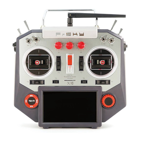
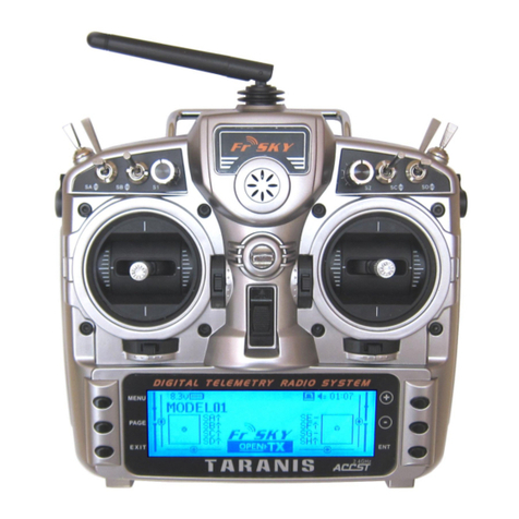
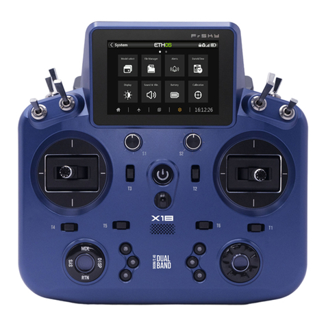
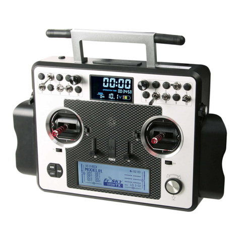
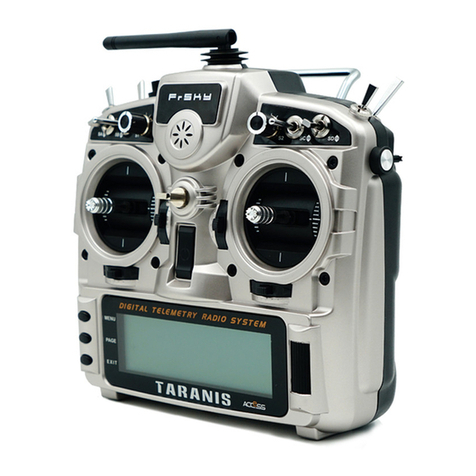
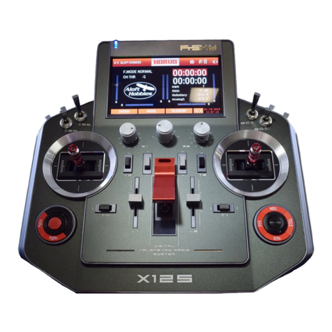
FrSky HORUS X12S User manual

2
Brief introduction
Thank you for purchasing FrSky HORUS X12S digital proportional R/C system (ACCST system).
This device has a wide range of functions and is developed for the beginners and skilled operators.
For the purposes of optimal use of the remote control device and flight safety, please read the
manual carefully before using. If you encounter difficulties during use, refer to the manual or FAQ
(Frequently Asked Questions) online at http://www.frsky-rc.com/, or consult with a local dealer or
FrSky technical support.
*ACCST: Advanced Continuous Channel Shifting Technology
User’s manual and technical support
We are aiming to help our users by thoroughly preparing this manual.
For any ambiguities or mistakes, please inform us of the mistakes that you have found.
In view of unforeseeable program changes of the product, the information contained herein is
subject to changes without timely notice. Your understandings will be highly appreciated.
Restrictions on sales and territory
If you have any questions or service demand, please contact your local FrSky dealers.
It should be noted that all information and technical support provided in the manual are only
pertaining to the devices sold within your region, and may be different from devices purchased in
other regions. Please contact your local FrSky dealers for help.
Provisions on use, export and quality guarantee
1. The product is applicable for the control of aerial models and ships and for the radio
application of land machines such as vehicles and robots within correct frequency range. It cannot
be used for any purposes other than remote control models for hobbies and entertainment.
2. Provisions on export
(a) When the product is sold from the country of production to abroad, it has been tested to
meet relevant regulations regarding radio transmission frequency required in the imported country.
Provided that the product is further exported to other countries, it shall also meet the relevant
regulations kind of devices being uphold in the imported countries, which may require approval
from the local regulatory departments. If you have purchased our products from foreign dealers
making the sales channels of the products not a normal distributor of the imported countries,
please contact an official dealer immediately to confirm whether it complies with your local
regulations.
(b) In case of using this product for purposes other than remote control, it will be restricted by
Export and Trade Control Regulations and application must be submitted for export permission.
3. Repair, adjustment and replacement of parts: FrSky can not be held responsible for any
unauthorized repair, adjustment and replacement of parts. All modifications to the product other
than by an approved dealer will render the warranty void.

3
Contents
Brief introduction...................................................................................................................... 2
User’s manual and technical support........................................................................................ 2
Restrictions on sales and territory ............................................................................................ 2
Notes for safe use ..................................................................................................................... 5
Meaning of symbols .......................................................................................................... 5
Flight safety precautions................................................................................................... 5
Safe use and handling of Ni-MH batteries ........................................................................ 6
Operation norm of SD card ............................................................................................... 8
Before use ................................................................................................................................. 8
Features of the HORUS X12S............................................................................................. 8
Micro SD Card(Secure Digital memory card)................................................................... 10
SYSTEM.................................................................................................................................... 12
MODEL SEL...................................................................................................................... 13
TIME ................................................................................................................................ 14
DISPLAY ......................................................................................................................... 144
SOUND ............................................................................................................................ 15
MUSIC ......................................................................................................................... 155
BATTERY .......................................................................................................................... 16
STK MODE ..................................................................................................................... 166
STK CAL............................................................................................................................ 17
STK (KNOB) DIR ............................................................................................................... 18
IMU CAL .......................................................................................................................... 18
TRAINER .......................................................................................................................... 19
INF................................................................................................................................... 20
MODEL(GENERAL FUNCTION)............................................................................................... 200
RF SYSTEM..................................................................................................................... 211
SERVO MONITOR........................................................................................................... 222
SERVO (CHANNEL) REVERSE............................................................................................ 23
SERVO SPEED................................................................................................................. 233
END POINT ...................................................................................................................... 24
SUB TRIM ...................................................................................................................... 255
TRIM STEP ..................................................................................................................... 255
FAIL SAFE ....................................................................................................................... 255
SPECIAL FUNCTION ....................................................................................................... 266
TELEMETRY SET ............................................................................................................. 277
SWITCH WARNING ........................................................................................................ 288
INPUT MAP...................................................................................................................... 28
OUTPUT MAP.............................................................................................................. 2929
CONDITION (HELICOPTER/GLIDER) ................................................................................. 29
MODEL (HELICOPTER) ........................................................................................................... 300
RATES/EXPO .................................................................................................................. 300
PITCH CURVE................................................................................................................. 311
THROTTLE CURVE.......................................................................................................... 311

4
THROTTLE HOLD............................................................................................................ 322
THROTTLE CUT .............................................................................................................. 322
THROTTLE MIX .............................................................................................................. 333
SWASH RING.................................................................................................................. 333
PITCH→RUDDER............................................................................................................ 344
GYRO ............................................................................................................................. 344
MODEL (FIXED-WING, GLIDER) ............................................................................................. 355
RATES/EXPO .................................................................................................................. 355
THROTTLE CUT .............................................................................................................. 355
THROTTEL HOLD............................................................................................................ 366
PITCH CURVE (FIXED-WING).......................................................................................... 366
THROTTLE CURVE (EXCLUSIVE FOR FIXED-WING)........................................................... 37
AILERON DIFFERENTIAL................................................................................................... 37
FLAP SET.......................................................................................................................... 38
AILERON→CAMBER FALP................................................................................................ 39
AILERON→ BRAKE FLAP .................................................................................................. 39
BRAKE FLAP→CAMBER FLAP ........................................................................................ 400
AILERON→RUDDER....................................................................................................... 400
RUDDER → AILERON ..................................................................................................... 411
RUDDER → ELEVATOR (FIXED-WING)............................................................................ 422
CABMER MIX................................................................................................................. 433
ELEVATOR→CAMBER .................................................................................................... 433
CAMBER FLAP → ELEVATOR.......................................................................................... 444
V-TAIL............................................................................................................................. 455
AIRBRAKE (FIXED-WING)................................................................................................. 45
SNAP ROLL (FIXED-WING) ............................................................................................... 46
AILERON ELEVATOR (FIXED-WING).................................................................................. 46
RUDDER SET (GLIDER) ..................................................................................................... 47
RATE/EXPO ...................................................................................................................... 48
MOTOR (GLIDER)............................................................................................................. 48
MOTOR CURVE (GLIDER) ................................................................................................. 49
BUTTERFLY (GLIDER) ....................................................................................................... 49
TRIM MIX (GLIDER) ....................................................................................................... 500
MODEL (MULTI-ROTOR) ........................................................................................................ 500
RATE/EXPO .................................................................................................................... 500
THROTTEL CURVE.......................................................................................................... 511
MODE............................................................................................................................ 522
GYRO ............................................................................................................................. 522
MODEL (CUSTOM MIX) ......................................................................................................... 533
MIXER............................................................................................................................ 533
OUTPUT MAP.................................................................................................................. 56
LOGIC SWITCH................................................................................................................. 56
SPECIAL FUNCTION ......................................................................................................... 57
CURVE LIB........................................................................................................................ 57

5
Notes for safe use
Please read the following notes thoroughly for your own safety:
Meaning of symbols
Contents marked with one of the following symbols in the manual require immediate
attentions.
Dangerous- This action can lead to death or serious injury to the user or others.
Warning- This action might lead to death or serious injury to the user or others. High risk
of minor injury and/or damages to the product.
Attention- Although such operation has a low risk of serious injury to the user or others,
personal injuries and/or damages to the product can still be possible.
Symbol : Prohibited : Required step
Flight safety precautions
Warning
Caution: read the following contents for your own or others’ safety;
Carry out regular maintenance. The data of HORUS X12S is stored on SD card, the data
can be not saved if the power is cut off directly, please follow the prompts when shut down the
radio, and regular check shall be done. We suggest full inspection and maintenance to the device in
the off-season annually to ensure safe operation.
Pay attention to charging. (Please refer to the manual for detailed information.)
Recharge the battery of the transmitter and receiver for at least eight hours before each flight. The
low battery shall run out soon, which may probably cause the receiver being out of control and
airplane crash. When starting the flight, the timer can be set at zero and you should pay close
attention to the duration of the battery during the flight.
Avoid flying during a low battery. Do not relay on the low battery alarm system of the
remote controller to tell you when to charge. Regularly check the battery of transmitter and
receiver before each flight.

6
Where to use
We recommend you to use it at a certified club for RC models. You can enquire at your local
dealer. In search of model clubs and fields.
Please pay close attention to the relevant regulations uphold at the flying field,
position of the spectators, wind direction and any obstacles inside the flying field, civil/military
aviation and the local wild life.
At the flying field
If you place the transmitter standing upright on the ground before taking off, make
sure the wind will not blow it over. If the transmitter is flipped on its front side, the throttle stick
may rotate and lead to a sudden increase of the engines rpm. The knockdown might also do
damage to the transmitter.
In order to remain in full control of the airplane, it is crucial to keep the plane well
within the limits of your eyesight. We do not recommend you to fly behind large objects such as tall
buildings, which may cause reduction of radio frequency quality connected to the model, and will
result in losing sign of sight.
Don't block the antenna located above the transmitter screen during the flight, which
may reduce the range of radio frequency transmission.
For all radio frequency transmission, the strongest signal transmission region usually
lies in the left side of transmitter antenna. Therefore, do not point the antenna directly at the
model. If this happens during flight, you only need to move the antenna to the right angle.
Don't fly it in the rain! The rain or moisture may come into the transmitter through the
crack of antenna or control rod, which may cause unstable flight and even runaway. If the flight in
wet weather is inevitable (such as races), please be sure to cover the transmitter with a plastic bag
or waterproof cloth. Flight is prohibited when lightning occurs.
Safe use and handling of Ni-MH batteries
Important
The user can only use power adapter matching with FrSky or approved by FrSky to charge the
battery of HORUS X12S transmitter.
It is important to be aware about the discharge characteristics of Ni-MH battery. Please replace
with info of used Ni-MH battery, battery in TX so need to open to read. If you do not follow the
instruction, there is a high chance of inflicting terminal damage to the battery or transmitter and
can even lead to fire.

7
Important notes
Do not try to disassemble the Ni-MH battery pack.
Keep the Ni-MH battery away from moisture or water at any time.
Ensure ventilation when charging and discharging the Ni-MH batteries and in the
process of use and storage.
Someone must be present during the charging and discharging cycle of the Ni-MH
batteries.
Do not charge a Ni-MH batteries with chargers non-dedicated to Ni-MH battery.
We must charge Ni-MH batteries in a fire-proof environment. Do not charge Ni-MH
batteries on carpet, on messed workbench and places close to paper, plastic, flammable, leather
and wood products. Do not charge Ni-MH batteries inside the model or car. It is better to equip fire
alarm in the charging area.
Do not charge Ni-MH batteries when you power on the radio.
Do not charge Ni-MH batteries with charging current over “1C” (C means battery
capacity.)
Do not let Ni-MH batteries overheating at any time! When the cell temperature is over
140 degrees Fahrenheit (60 degrees Celsius), the battery shall be put in a fire-proof environment.
When Ni-MH batteries indicate to be fully charged in a cold environment, they are not
fully charged as the low temperature has an effect on the total battery capacity.
It is normal that a certain temperature rise will happen during charging. However, if
the charger or battery is overheating, the battery must be removed from the charger immediately.
Close observation shall be paid to the overheating battery. If you suspect that the battery has been
damaged, do not use it any more in any case.
Do not store batteries near an open flame or any other source of high temperatures.
Do not discharge Ni-MH batteries with discharge current exceeding the rated standard.
Ni-MH batteries must be kept in a safe place away from children.

8
Operation norm of SD card
When transferring data, do not turn off the power or extract the SD card.
Keep SD card clean. Keep the SD card away from moisture, water and any liquid.
Don't keep the SD card in environment with strong electromagnetism.
Hold the edge of the card when installing or removing the card.
Do not expose the SD card to direct sunlight nor store them in damp and corrosive
environment.
Check the orientation of the SD card before inserting, to ensure correct insertion.
Before use
Features of the ACCST-2.4G HORUS X12S
Unique frequency ID to avoid interference with other ACCST devices.
Real-time telemetry of data
Programmable Fail Safe functions
Dual receiving antennas
Compatibility setting transmitter and receiver
HORUS X12S working mode
Compatible receiver
Output number of
channels
D8
V8-II series in D mode
(V8FR-II, V8R7-II, V8R4-II, VD5M, etc.)
D series
(D8R-II plus, D8R-XP, D6FR, D4R-II, etc.)
8 channels
D16
X series
(X8R, X6R, X4R, X4RSB, XSR, etc.)
Up to 16 channels
LR12
L series
(L9R, etc.)
12 channels
The obsolete V8 series receiver is not compatible with the internal RF module, but can still
be used in combination with an external DJT module.
The LBT version of HORUS X12S only has FrSky D16 and LR12 Mode.

9
Model types
Helicopters models have six different types of swash plate modes. Fixed-wing aircraft have
three modes, gliders have two modes and one multi-rotor mode. Besides this, there is also a fully
custom model creation option.
Display
Industrial grade color display, high resolution (480x272), readable outdoor.
Sticks
CNC milled aluminum parts, fitted with 6 ball bearings in a single unit (2 on the return to
center mechanism) combined with HALL sensors, for a superior feel of quality, precision and
durability.
Integrated sensor
Built-in 6-axis orientation sensors to enhance somatosensory auxiliary control
Vibration function
Selects a function that alerts the operator to various alarms by vibrating the transmitter.
Smart antenna detection
SWR telemetry data is used for real-time monitoring of signal performance at the transmitting
end. If the value is outside the reprogrammed value, an automatic alarm will be generated by the
system.
Entertainment function
The transmitter has 2 speakers and an internal MP3 player. You can play save files from the
(pre-) installed SD card, via the MP3 menu found under the System selection button.
Wireless Trainer system
8 channels of data transmission and a simpler and more convenient connection setting.

10
Micro SD Card (Secure Digital memory card)
You will find a variety of files such as videos, artworks for icons, voice files, detailed user guide,
etc. on the pre-installed MicroSD card in HORUS X12S TF Card Slot.
Be sure to turn off the power to the transmitter before inserting or removing the
Micro SD card.
As the Micro SD card is a precision device, do not use excessive force when inserting.

11
Main interface
The System menu is primarily used for setting up the system settings of the transmitter. Select
the SYS key on the main interface to enter the interface of system settings menu.
Main screen (page 1/3)
The flight condition and total flight time are displayed on the top left of the screen and on the
right side are two timers followed by real-time data related to the RF system.
Main screen (page 2/3)
This screen selection is used for confirming whether all operating sticks, switches and knobs
are functioning properly.
Main screen (page 3/3)
This screen selection is used for displaying and recording latitude and longitude information
from the RX GPS module.

12
SYSTEM
Overview of system menu
Option list of system menu
[MODEL SEL]: Is used to create new, select between, modify, copy or delete existing models.
[TIME]: Is used to adjust the time, date and the order in which the date is displayed.
[DISPLAY]: Allows adjustment to screen brightness and the option to assign a knob to manually
adjust the intensity of the back-light.
[SOUND]: Volume adjustment, muting and assigning knobs and sliders to adjust individual
sound levels manually is all done in this menu.
[MUSIC]: Allows access to the internal MP3 Player, selecting audio files saved on the SD card
and assigning knob or slider for manual volume control can be done in this menu.
[BATTERY]: Displays the current voltage of the transmitter battery, low-battery warning and
range of working voltage can be adjusted in this menu.
[STK MODE]: Is used to select stick mode (Mode1, Mode 2 etc.)
[STK CAL]: Is used to calibrate the endpoints of the sticks, knobs, switches and sliders.
[STK DIR]: Allows reversing of the stick, knob, slider and switch signal.
[IMU CAL]: Is used to calibrate the triaxial accelerometer.
[TRAINER]: This menu gives access to the trainer function, all relevant programming is done
here.
[INFO]: Displays software and hardware information concerning the transmitter.

13
MODEL SEL
Select MODEL SEL in the system menu to enter the following menu selection.
After selecting the menu, the name, model and model picture are displayed on the right of the
screen and on the left is the operating part for model files. Select MODEL SEL to browse files of the
existing models. Push the ROLLER button, on the right from top to bottom are “create, select,
modify, copy and delete”. When you create or modify a model, the menu screen illustrated next will
pop up.
Here you can define the following three parameters, name, type and image. The selection of
model type here is very important! An incorrect selection of the model type will lead to unexpected
system behavior, which may lead to serious injury or death to you and others around you.

14
TIME
Select TIME in the system menu to enter the menu section illustrated below.
Changes to the displayed time can be done in this menu. The user can also set and adjust date
and time in accordance with region and time zone, the system can also display different date
formats.
DISPLAY
Select DISPLAY in the system menu to enter the illustrated menu screen.
You can adjust the brightness of the screen and activate the sleep function. The screen will
turn of after a programmed amount of time, and turn on when the programmed conditions are met.
According to personal needs and changes in light conditions, a knob can be assigned to manually
change the brightness for the best visual effect, these settings can optimize readability and prolong
battery endurance.

15
SOUND
Select SOUND in the system menu to enter the illustrated menu screen.
You can adjust system sound volume according to personal preference, including on and off of
key tone and system alerts (voice alarming), on and off of vibration, adjustment to volume and
vibration intensity to meet different experience of diversified users, which is more personalized.
MUSIC
You can play audio files saved in SD card on the interface of this function. There are four
control assemblies on this interface, previous, play/pause, next and volume.
You can add .mp3 file to the MUSIC folder of Micro SD card.

16
BATTERY
Select BATTERY in the system menu to enter the illustrated menu screen.
In the menu of this feature, the screen will display the current voltage of the transmitter
battery, the user can also adjust the activation voltage of the low voltage protection alarm. The
working range of the battery can be changed to keep a functional main-screen battery icon after
installing a different type of battery. The system will generate a low voltage alarm to prevent a low
voltage induced shut down of the transmitter. Never use or continue flying after a low voltage
alarm!
STK MODE
Select STK MODE in the system menu to enter the following setting interface.
In the menu of this feature, the system provides four different stick modes to choose from
(Mode1, Mode2, and Mode3 etc.). The user can select the suitable flight mode according to
personal preference to get best possible flight experience.

17
STK CAL
Select STK CAL in the system menu to enter the illustrated menu screen.
In the menu of this feature, the user can calibrate the sticks, knobs and sliders. We advise you
to perform this task after each software update.

18
STK (KNOB) DIR
Select STK DIR in the system menu to enter the illustrated menu screen.
In the menu of this feature, the system displays hardware and type. The user can change
"type" on all hardware inputs and adjust the direction of the corresponding signal to be able to set
the required direction.
IMU CAL
Select IMU CAL in the system menu to enter the illustrated menu screen.
On the interface of this function, the user can calibrate the triaxial accelerometer, please
follow the instructions and calibrate it when holding it as you would during normal use, when
calibrated the G-ROLL, G-PITCH channel have a corresponding output signal.

19
TRAINER
Select TRAINER in the system menu to enter the illustrated menu screen.
In the menu of this feature, the user can choose the preferred connection methods, according
to personal preference control can be claimed (Master) either via a switch or by directly overriding
the controls. The end points of all channels (Slave) can be reduced according to the proficiency of
the student to ensure a safe flight.
Select WL TRAINER on the top right corner of the screen to enter the illustrated menu screen
shown below.

20
The user can select wireless trainer mode in the top-left corner and select master or slave at
“TYPE”(note: If you choose the wireless trainer mode, you need to choose “SLAVE” type and turn
on the student’s transmitter firstly, then choose “MASTER” type and turn on the instructor’s
transmitter ). The remaining functions are used to display some basic information about the paring
of wireless trainer.
INF
Select INFO in the system menu to enter the illustrated menu screen.
The hardware version information, and the internal module version of IXJT are displayed on
this Information screen, which can be used as a reference when checking for a firmware updates.
MODEL (GENERAL FUNCTION)
The “MODEL” menu is used to set up the selected model, the content of this menu changes
with the type of model selected. There are a number of programmed mixes available for the
selected type, the “custom” model selection allows the use of “logic switch” programming for a
nearly endless amount programming possibilities.
Other manuals for HORUS X12S
2
Table of contents
Other FrSky Remote Control manuals

FrSky
FrSky Taranis X-Lite User manual

FrSky
FrSky E-Soar User manual

FrSky
FrSky DLG User manual

FrSky
FrSky V8HT User manual

FrSky
FrSky HORUS X12S User manual

FrSky
FrSky TARANIS Q X7 User manual

FrSky
FrSky D8R-II plus User manual

FrSky
FrSky Taranis X9D Plus User manual

FrSky
FrSky Taranis User manual

FrSky
FrSky ACCST Taranis X9E User manual

FrSky
FrSky DFT User manual

FrSky
FrSky TWIN X14S User manual

FrSky
FrSky Taranis X9D Plus User manual

FrSky
FrSky HORUS X10S User manual

FrSky
FrSky TANDEM X18SE User manual

FrSky
FrSky TARANIS X9D User manual

FrSky
FrSky TARANIS X9D User manual

FrSky
FrSky TWIN X14 User manual

FrSky
FrSky TANDEM X20 User manual

FrSky
FrSky TANDEM X18S User manual