FrSky DLG User manual

Doc version 008 Page 1
CONTENTS
1 Introduction ..............................................................................................................................................................2
1.1 Description ........................................................................................................................................................................ 2
1.2 Package contents............................................................................................................................................................... 2
1.3 Requirements .................................................................................................................................................................... 2
2 Overview ...................................................................................................................................................................3
2.1 Stick mode and switch assignments.................................................................................................................................. 3
2.2 Flight modes ...................................................................................................................................................................... 3
2.3 Servo assignments............................................................................................................................................................. 3
2.4 Mixer table ........................................................................................................................................................................ 3
2.5 Flight timer ........................................................................................................................................................................ 4
2.6 CAL mode .......................................................................................................................................................................... 4
2.7 Basic operation.................................................................................................................................................................. 4
2.8 The flight sequence ........................................................................................................................................................... 5
3 Preparing the transmitter .........................................................................................................................................5
3.1 Transfer template to transmitter ...................................................................................................................................... 5
3.2 Hardware calibration......................................................................................................................................................... 5
3.3 Telemetry .......................................................................................................................................................................... 5
3.4 Familiarisation ................................................................................................................................................................... 6
4 Calibrating the outputs (servos)................................................................................................................................6
4.1 Set servo rotation.............................................................................................................................................................. 6
4.2 Adjust servo end points and centres ................................................................................................................................. 6
5 Configuring travel and mixers...................................................................................................................................8
5.1 Aileron, elevator and rudder travel (Inputs menu) ........................................................................................................... 8
5.2 Aileron diff (rudder trim)................................................................................................................................................... 8
5.3 Rudder launch offset (gv: Rud).......................................................................................................................................... 9
5.4 Elevator launch offset........................................................................................................................................................ 9
5.5 Brake travel (gv: Brk→FM4) .............................................................................................................................................. 9
5.6Superdiff (gv:SDf→FM4).................................................................................................................................................... 9
5.7 Camber/Reflex presets (throttle trim) .............................................................................................................................. 9
5.8 Snapflap (gv:SnF)............................................................................................................................................................... 9
5.9 Ail=>Rudder (gv:A2R) ...................................................................................................................................................... 10
6 Flying notes.............................................................................................................................................................10
6.1 Adjusting pitch trim in Landing mode ............................................................................................................................. 10
7 Customising your setup...........................................................................................................................................10
7.1 Changing the main flight mode switch............................................................................................................................ 10
7.2 Configuring Thermal 1/thermal 2 mode switch .............................................................................................................. 10
7.3 Hiding Thermal 2 ............................................................................................................................................................. 11
7.4 Changing the Launch and CAL switch.............................................................................................................................. 11
7.5 Changing the CAL submode switch ................................................................................................................................. 11
7.6 Adding rates .................................................................................................................................................................... 11
7.7 Reversing the brake stick................................................................................................................................................. 12
7.8 Launch height announcement......................................................................................................................................... 12
7.9 Setting diff adjustment range.......................................................................................................................................... 12
7.10 Adjusting brake stick deadband ...................................................................................................................................... 12
7.11 Zoom Safe Exit (ZSE)........................................................................................................................................................ 12
7.12 Making your own modifications...................................................................................................................................... 12
8 Disclaimer................................................................................................................................................................13
Doc version 008 Page 2
1INTRODUCTION
1.1 DESCRIPTION
DLG is a full feature template for four-servo DLGs. Yet it is quick to set up, and fully customisable. Full
documentation is provided. Version 2 features several improvements for even quicker setup, easier trimming and
direct adjustment of camber.
Specification:
APPLICATION
- For DLG gliders with two wing servos
- Any stick mode
- Freely assignable switches
LAUNCH HEIGHT CALLOUT
- Optional launch height callout (using ALT telemetry)
7 FLIGHT MODES
- Launch followed by Zoom
- Thermal1, Thernal2, Cruise, Speed
- Landing
- Voice confirmation
IN-FLIGHT ADJUSTERS
- Adjuster for aileron diff (per FM)
- Adjuster for camber (per FM)
- Adjuster for brake compensation
SNAPFLAP
- Snapflap, preset per flight mode.
CONTROL SURFACE CALIBRATION
- Special 'CAL' mode for quick calibration
- 5-point balancing curve for flaps
CROW BRAKE FEATURES
- compensation adjustment using regular elevator trim
- super diff for better roll response under braking
MISC
- Flight timer
- Aileron to rudder mix
- Channels 7,8,9 free for other functions
Now begin your journey to a great DLG setup! But first, here are the golden rules for success:
- READ THROUGH THESE INSTRUCTIONS ONCE BEFORE STARTING!
- FOLLOW THE INSTRUCTIONS IN SEQUENCE!
1.2 PACKAGE CONTENTS
What’s included in the ZIP file:
Filename
Description
DLG_21_SetupGuide.pdf
This document
DLG_21_SettingsRef.xls
Settings reference
DLG_21*.otx
Model settings
Dl1***.wav
Sound files
DLG_21_Zorro-addendum.pdf
Addendum with mods for RM Zorro
1.3 REQUIREMENTS
The following are required:
•Any OpenTX transmitter with OpenTX 2.2.2 or later
•A momentary switch on the correct side, for launching
•OpenTx Companion software + USB cable.

Doc version 008 Page 3
2OVERVIEW
2.1 STICK MODE AND SWITCH ASSIGNMENTS
Any stick mode may be used. The stick mode is set in the RADIO SETUP →MODE menu.
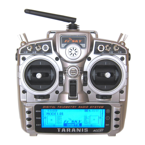
The default switch assignments are designed for the Taranis X9D. If using a different radio, check that the switches
are of the correct type, and re-assign if necessary.
Function
Switch type
Default
How to re-assign
Main flight mode switch
3-pos
SA
see section 7.1
Launch, CAL modes
Momentary
SH
see section 7.4
CAL submode
2- or 3-pos
SA
see section 7.5
Thermal1, Thermal2 modes
2- or 3-pos
SF
see section 7.2
Brakes/landing mode
Throttle stick
Aileron diff adjustment
Rudder trim
Camber adjustment
Throttle trim
2.2 FLIGHT MODES
There are 7 flight modes: Launch, Zoom, Landing, Thermal1, Thermal2, Cruise and Speed.
Launch and Zoom have highest priority. Landing has priority over Thermal, Cruise and Speed.
Flight Mode
ID
Activation switches (defaults shown)
Priority
Launch
FM2
SH↓ (momentary switch)
High
Zoom
FM3
Follows Launch mode. Down eleva to exit
High
Landing
FM4
Throttle stick ↓ (activates brakes)
Mid
Cruise
FM0
SA ―
Low
Speed
FM5
SA ↑
Low
Thermal 1
FM6
SA ↓ and SF↑
Low
Thermal 2
FM7
SA ↓ and SF↓
Low
2.3 SERVO ASSIGNMENTS
Channel
Function
1
Rudder
2
Elevator
3
Left aileron
4
Right aileron
The left and right channels are not interchangeable –please ensure they are connected correctly!
Channel assignments can be changed using the author’s ChannelChanger script.
2.4 MIXER TABLE
The table below shows the mixers in each flight mode. Mix adjusters are in brackets.
Flight
mode
Diff
Ail=>
Rud
Brakes
Brake
Comp
Rudder
offset
Camber/
Reflex
Snapflap
Launch
✓(RudTrm)
✓
✓
✓(Thr trim)
✓
Zoom
✓(RudTrm)
✓
✓(Thr trim)
✓
Landing
✓(RudTrm)
✓
✓
✓(Ele trim)
✓(Thr trim)
✓
Thermal1/2
✓(RudTrm)
✓
✓(Thr trim)
✓
Speed
✓(RudTrm)
✓
✓(Thr trim)
✓
Cruise
✓(RudTrm)
✓
✓(Thr trim)
✓

Doc version 008 Page 4
2.5 FLIGHT TIMER
Timer1 is the flight timer.
•To reset and start: release Launch switch
•To stop: pull and hold Launch switch
2.6 CAL MODE
CAL mode is a special flight mode for calibrating the outputs. When CAL is activated, trims are ignored and stick
values are passed directly to the outputs. This allows end points and centres to be visualised. To activate CAL mode:
1. Apply full left aileron and full up elevator, and hold.
2. Pull and release SH
3. Release sticks.
4. Listen for voice confirmation.
5. Select the appropriate submode (‘calibration’ or ‘calibrate flap neutral’).
Sub mode
Switch
Description
Calibration
SA― or
SA↑
for calibrating end points and centres. The flapperons move in 25%
increments.
Calibrate flap neutral
SA↓
for calibrating the flapperon neutral offset
To exit CAL mode, pull SH.
Note for v2.1: when entering CAL mode, Launch mode is activated briefly –this is expected behaviour.
2.7 BASIC OPERATION
Trims
•Aileron trim is shared across all flight modes.
•Elevator trim is independent in each flight mode (but see section 6.1 for Landing mode).
•Rudder trim is repurposed to adjust differential.
•Throttle trim adjusts camber per flight mode.
Launch offsets
•The rudder offset is adjusted via a GVAR.
•The elevator offset is adjusted using the regular elevator trim
Aileron differential
•Aileron diff is adjustable per flight mode, via the rudder trim.
Camber control
•Camber/reflex is adjustable using the throttle trim in all flight modes.
Brake compensation (brake=>elevator)
•Counteracts pitching due to deployment of brakes.
•The compensation at full brake can be adjusted in flight, via the elevator trim.
•The compensation with partial brake can be tuned by editing the compensation curve.
Aileron=>rudder mix
•Aileron=>rudder mix can be set per flight mode.
Snapflap
•Snapflap (elevator=> ail) can be preset per flight mode.

Doc version 008 Page 5
2.8 THE FLIGHT SEQUENCE
The flight sequence is as follows:
1. Rotate the model whilst pulling the launch switch. Model is in Launch mode.
2. As the model leaves the hand, release the launch switch. Model enters Zoom mode.
3. Near the top of the climb, push forward on the elevator stick. Model exits Zoom mode.
4. Once out of Zoom mode, the flight mode is determined by flight mode switch (default SA) and throttle stick.
3PREPARING THE TRANSMITTER
3.1 TRANSFER TEMPLATE TO TRANSMITTER
Start by transferring the template to your transmitter. The model is not needed for this step.
Establish a USB connection
1. Enter Bootloader mode (the exact method will depend on your transmitter).
2. Connect to PC via USB. The tx’s SD card should appear as an external drive.
Copy sound files
1. Copy the supplied sound files to the /SOUNDS/{language} folder on the SD card. For example, the English
folder is /SOUNDS/en. Note: version 2 has some new sound files, do not skip this step!
Transfer template to transmitter
1. Start the Companion software, using the correct profile for your transmitter
2. Open supplied file DLG_21.otx.
3. If using a transmitter other than the X9D, you may receive warnings that certain switches are not available.
Make a note of the warnings, and reassign switches if necessary (see section 2.1).
4. From the File menu, choose Read Models and Settings From Radio. The models from the radio are displayed
in a second window.
5. Drag the DLG_21 model into an empty slot in the model list.
6. Close the DLG_21.otx window.
7. From the File menu, choose Write Models and Settings To Radio.
8. Close OpenTx Companion
3.2 HARDWARE CALIBRATION
The transmitter hardware (sticks, sliders etc.) must be properly calibrated, so do so now if you haven’t already
calibrated or are not sure. To do a hardware calibration:
1. Open the RADIO SETUP menu and page to Hardware -> Calibration (Horus) or Calibration (Taranis)
2. Calibrate all sticks, knobs and sliders.
3.3 TELEMETRY
Check that your transmitter is receiving telemetry (if supported by the protocol and module). If you encounter
problems, try rediscovering your sensors as follows:
1. Open the TELEMETRY menu
2. Choose ‘Delete all sensors’ then ‘Discover sensors’
RSSI low/critical warning thresholds are set to 45/42. If using the FrSky ACCESS protocol, change to 35/32 (FrSky
recommendation).

Doc version 008 Page 6
3.4 FAMILIARISATION
Using the transmitter on its own, practise the following:
•Activate Launch, Zoom, Thermal1, Thermal2, Cruise, Speed and Landing modes (see Section 2.2).
TIP: start with the throttle stick pushed fully forward.
•Activate CAL mode and sub-modes (see Section 2.6)
•Start/stop/reset the flight timer (see Section 2.5)
•Verify that the sounds are working correctly. If not, check that the sound files are in the correct location.
4CALIBRATING THE OUTPUTS (SERVOS)
In this section you will set the rotation and operating range of the servos.
4.1 SET SERVO ROTATION
First, set the rotation of each servo:
1. Switch on the transmitter (do not power up the receiver yet)
2. Move the elevator stick, and check for correct direction of elevator surfaces. If necessary, reverse the direction of
the output (see below).
3. Repeat for the rudder and ailerons. Note: the throttle (brake) stick will have no effect yet.
To change the direction of an output:
1. Go to the Direction field
2. Press {enter}, and immediately {exit}
4.2 ADJUST SERVO END POINTS AND CENTRES
The next task is to set the operating limits of the servos. At the same time, you will compensate for linkage
differences between the left and right sides of the model. All the adjustments are made in CAL mode.
When making the adjustments:
•Set the servo end points to the maximum as limited by the linkages and hinges. You may need to refine the
adjustments to achieve symmetry –this is described in each step.
•Adjustments are made using curves. Do not alter min, max or subtrim!
Notes for radios with lo-res mono screens (X-Lite, TX12, Zorro etc.)
To edit a curve on these radios and also on radios running EdgeTX, you must close the OUTPUTS menu,
then open the CURVES menu ().
These radios also lack a dedicated GLOBALVARS menu. Instead, GVARs are accessed through the FLIGHT
MODES menu.

Doc version 008 Page 7
Channel
Calibration procedure
CH 1 –Rudder
CALibrate the rudder
1. Activate CAL mode
2. Open the OUTPUTS menu
3. Highlight the rudder channel (default CH1)
4. Go to the curve field ‘Rud’, press {long enter } to open curve editor
5. With stick in centre, adjust point 2 so rudder is central
6. Move Rudder stick right (→), then set point 3 for max right movement
7. Move Rudder stick left (←), then set point 1 for max left movement
8. Check equal travel left/right, reduce one or other side if necessary.
CH 2 –Elevator
CALibrate elevator.
IMPORTANT: in CAL mode, the elevator moves in the opposite direction to
normal.
1. Activate CAL mode
2. Open the OUTPUTS menu
3. Highlight the Ele channel (default CH2)
4. Go to the curve field ‘Ele’, press {long enter } to open curve editor
5. With Ele stick at centre, adjust point 2 so elevator is central
6. Move Ele stick forward (↑), then adjust point 3 for upper limit
7. Move Ele stick back (↓), then adjust point 1 for lower limit
8. Check elevator travel is equal up & down, reduce one or other side as
necessary.
CH 3 –Lt Ail
Calibrate the left aileron:
1. Activate CAL mode, select ‘Calibration’ submode
2. Go to OUTPUTS menu
3. Highlight left aileron channel (default CH3)
4. Go to the curve field LtA, and press {long enter} to open curve editor
5. Throttle stick fully back (↓), adjust point 1 for lower end point.
6. Throttle stick fully forward (↑), adjust point 3 for upper end point.
7. Adjust point 2 so it lies on the straight line between points 1 and 3. Do not
worry that the point 2 does not correspond to the airfoil centre line –that
will be fixed later.
Move throttle stick from one end to the other, observing step intervals. If they
are grossly unequal, adjust point 2 to for better linearity.
CH 4 –Rt Ail
Next, CALibrate the right aileron so it precisely matches the left aileron:
1. Activate CAL mode, select ‘Calibration’ submode
2. Return to OUTPUTS menu
3. Highlight the right aileron channel (default CH4)
4. Go to the curve field RtA, press {long enter} to open curve editor
Adjust points 1 –5 to exactly match the let aileron:
5. Stick fully back, adjust point 1
6. Stick ½-back, adjust point 2
7. Stick to centre, adjust point 3
8. Stick to ½-forward, adjust point 4
9. Stick fully forward, adjust point 5
To match the end points on left and right sides, it may be necessary to reduce
one or other end points for the left aileron.

Doc version 008 Page 8
Channel
Calibration procedure
Aileron offset
Next, CALibrate the aileron offset:
1. Activate CAL mode
2. Select ‘calibrate flap neutral’ submode.
3. Page to GLOBALVARS menu.
4. Go to cell GV5:Fof→FM0 (Note FM0, not FM1)
5. Adjust offset so that ailerons follow the neutral profile
If ailerons are not in line, redo the calibration of the left aileron (see above),
paying attention to the points either side of the neutral position.
Check operation:
1. Exit CAL mode
2. Move the sticks, checking that aileron, elevator and rudder control surfaces move in the correct sense.
Note that the throttle stick (for brakes) will not function yet (it will be configured in the next section).
3. The travel will be excessive –don’t worry, it’ll be dialled down in the next section.
5CONFIGURING TRAVEL AND MIXERS
In the final section, you’ll set the control travel (‘rates’) and mixers. Watch your model come to life!
5.1 AILERON,ELEVATOR AND RUDDER TRAVEL (INPUTS MENU)
In this section, you’ll reduce the rates of the main flight controls, to achieve the required travel.
1. Activate Cruise mode
2. Open the INPUTS menu
3. Scroll down to [I]Ail, [I]Ele or [I]Rud as required
4. Press {LONG ENTER} and choose Edit
5. Go to the weight field
6. Adjust weight for required travel.
7. To add expo, go to the Curve field, and change the curve type from ‘Diff’ to ‘Expo’. Set required value.
When adjusting aileron travel, consider upward travel only (downward travel will be adjusted when setting diff, in
the following section.)
5.2 AILERON DIFF (RUDDER TRIM)
Aileron differential alters the downward travel of the ailerons in response to roll commands.
Diff is adjusted using the rudder trim. As the trim is moved from left to right, the amount of Diff decreases thus
increasing the roll rate –think of the trim as a roll rate adjuster.
The range of diff adjustment can be changed (see section 7.9).
New in v2.1: The default minimum diff has been changed to -30%, allowing down-travel to exceed up-travel as is
required for some DLG setups.
Diff settings are stored independently for each flight mode - make sure to set diff correctly for each flight mode.

Doc version 008 Page 9
5.3 RUDDER LAUNCH OFFSET (GV:RUD)
Counteracts rotation of the model following launch. Adjust as follows:
1. Open the GLOBALVARS menu
2. Go to row ‘Rud’, column FM2:Launch
3. Pull on the Launch switch, and hold.
4. Adjust the GV for required offset
5. Release the Launch switch
6. Push forward on elevator stick to exit Zoom mode.
5.4 ELEVATOR LAUNCH OFFSET
There is no dedicated elevator offset adjustment. Instead, activate launch mode and adjust the elevator trim.
5.5 BRAKE TRAVEL (GV:BRK→FM4)
Set the brake=>aileron travel as follows:
1. Open GLOBALVARS menu
2. Enable Landing mode
3. Move throttle stick back (full brake)
4. Go to row ‘Brk’, column FM4:Landing
5. Adjust for required down movement
5.6 SUPERDIFF (GV:SDF→FM4)
Superdiff is an optional adjustment which may improve roll response under braking. As the brakes are applied, the
travel of the rising aileron (in response to a roll command) is gradually increased by the amount that you specify. Try
a small amount first, as too much can adversely affect handling.
To set the amount of Superdiff:
1. Open the GVARS and scroll to line GV6:SDf.
2. Go to the FM4 column (for Landing mode).
3. Enter Landing mode and apply full brakes and full aileron
4. Adjust GV as required
5.7 CAMBER/REFLEX PRESETS (THROTTLE TRIM)
Camber and reflex are adjustable independently in all flight modes.
The amount of camber is adjusted using the throttle trim:
•Trim centre = zero camber
•Trim forward = reflex
•Trim back = +ve camber
New in v2.1 In Landing mode, adjusts the ‘starting’ camber.
5.8 SNAPFLAP (GV:SNF)
Snapflap (Ele=> aileron) is adjustable per flight mode. Adjust as follows:
1. Open GLOBALVARS menu, go to row ‘SnF’
2. Activate flight mode to be adjusted - the column is highlighted
3. Adjust value in highlighted column

Doc version 008 Page 10
5.9 AIL=>RUDDER (GV:A2R)
This mix can help the model enter the turn. Adjust per flight mode as follows:
1. Open GLOBALVARS menu, go to row ‘A2R’
2. Activate flight mode to be adjusted - the column is highlighted
3. Adjust value in highlighted column
6FLYING NOTES
6.1 ADJUSTING PITCH TRIM IN LANDING MODE
Version 2 features Supertrim. This is a simple way of adjusting pitch trim in Landing mode, using the same trim lever
for both the base trim and the compensation. The adjustment procedure is as follows:
1. Enter Cruise mode and adjust base trim as normal, using the elevator trim.
2. Now enter Landing mode, and apply 75% - 100% brakes. Still using the elevator trim, adjust the
compensation as follows:
•Trim fully back = zero compensation
•Trim fully forward = 80% down elevator
Technical note: In Landing mode, (a) The base trim is shared from Cruise mode and (b) the function of the elevator
trim lever changes so that it becomes an adjuster for the compensation mix.
Adjusting the compensation curve.
Once the compensation is adjusted, the response with partial brake can be tuned by editing curve CV7:BrC. Alter
points 2 –4 only. The default curve is a typical ‘S’ shape.
7CUSTOMISING YOUR SETUP
This section describes how to customise your setup. You can customise at any time without breaking the setup.
7.1 CHANGING THE MAIN FLIGHT MODE SWITCH
Main flight mode switch
The main flight mode switch is defined in logical switches L2 and L3:
Function
Menu point
Assign to
Default
Speed mode
LOGICALSWITCHES→L2→V1
3-pos switch
SA↑
Thermal mode
LOGICALSWITCHES→L3→V1
SA↓
The same 3-position switch must be used for both flight modes.
Cruise mode is automatically assigned to the remaining position.
7.2 CONFIGURING THERMAL 1/THERMAL 2MODE SWITCH
By default, two alternative thermal modes are available Thermal_1 and Thermal_2. The selection switch can be 2- or
3-position, and is defined in logical switch L28:
Function
Menu point
Assign to
Default
Thermal_2 select
LOGICALSWITCHES→L28→V2
2- or 3-pos switch
SF↓
The remaining switch position(s) are assigned to Thermal 1.

Doc version 008 Page 11
7.3 HIDING THERMAL 2
If you prefer, you can hide thermal_2. In that case, only thermal_1 is available; the selector switch (default SF) can
then be re-used for another function.
Function
Menu point
Value
Default
Thermal_2
enable
LOGICALSWITCHES→L4→V2
99 = disabled
100=enabled
Enabled
If hiding Thermal_2 mode, you may wish to change the sound file for Thermal_1 to say just ‘thermal’ or ‘slow’.
Suitable WAV files are provided in the package, assign in the SPECIAL FUNCTIONS menu=>SF9.
7.4 CHANGING THE LAUNCH AND CAL SWITCH
Launch and CAL modes share the same momentary switch, default SH. On some radios, SH is a regular 2- or 3-pos
switch, and it will be necessary to reassign to the momentary. To do this, edit logical switch L1:
Function
Menu point
Assign to
Default
Launch/CAL switch
LOGICALSWITCHES→L1→V1
Any momentary switch
SH↓
SAFETY: The switch must be a momentary type, do not use a regular switch!
7.5 CHANGING THE CAL SUBMODE SWITCH
The CAL submode switch selects between ‘normal’ and ‘aileron neutral’ calibration modes. It must be a regular 2- or
3-position switch. The default is SA, however on some radios SA is a momentary switch. To reassign the CAL
submode switch, edit logical switch L5:
Function
Menu point
Assign to
Default
CAL Submode switch
LOGICALSWITCHES→L5→V1
Any 2- or 3-pos switch
SA↓
7.6 ADDING RATES
Rates are managed in the INPUTS menu. To add a new rate:
1. Go the INPUTS menu.
2. Highlight the last line in the target group (Ail, Ele or Rud).
3. Press {long Enter} and choose ‘Insert Before’
4. Create a new input line.
5. Set source = Ail/Ele/Rud as appropriate
6. Set weight to the new rate.
7. Set expo as required
8. Tick applicable flight modes (0: Cruise, 2: Launch, 3: Zoom, 4: Landing, 5: Speed, 6: Thermal2, 7: Thermal1).
(Alternatively, you can select via a switch instead of via flight modes.)
Here is an example showing triple aileron rates linked to flight modes. Rate = 50% for FM5, and 80% for FM4. For all
other flight modes, rate = 75%.
The last (or only) line in each group must have all flight modes checked, and switch = ‘---'. This provides a safe
fallback in case none of the previous lines is selected due to a data entry error. For a deeper explanation see ‘more
about inputs’.

Doc version 008 Page 12
7.7 REVERSING THE BRAKE STICK
By default, zero brake is with the throttle stick forward. To reverse the stick:
1. Open the MIXER menu
2. Go to CH23:RawBr
Go to the Curve field, and change the curve from CV9:Thr to CV9:!Thr (note leading ‘!’).
7.8 LAUNCH HEIGHT ANNOUNCEMENT
If you have ALT telemetry, you can enable the announcement of launch height. This is the difference between the
height at launch, and the maximum height achieved until 3 seconds after exiting Zoom mode. Configure as follows:
Function
Menu point
Note
Callout
enable/disable
SPECIAL FUNCTIONs→SF14
Disabled: L26, ‘---’ (default)
Enabled: L26, ‘ALT+’(make sure to discover sensors first,
otherwise ALT+ will not be available)
Callout Zoom delay
LOGICAL SWITCHES→L25→Duration
Default=3secs
7.9 SETTING DIFF ADJUSTMENT RANGE
Aileron diff is adjusted via the rudder trim. The default range is −30% to +70%. The range can be adjusted by editing
the end points of curve CV10:Dif.
7.10 ADJUSTING BRAKE STICK DEADBAND
The brake stick incorporates some deadband to prevent accidental deployment. The amount of deadband can be
adjusted as follows:
Function
Menu point
Value
Default
Brake stick deadband
CURVES→CV9:Thr
Set point 2 for required deadband
85
7.11 ZOOM SAFE EXIT (ZSE)
Zoom mode is exited by pushing forward on the elevator stick. With the default configuration, the pilot must ensure
that the brake stick is in the ‘off’ position when exiting Zoom mode, otherwise the brakes will deploy suddenly.
Zoom Safe Exit (ZSE) is an optional interlock which prevents this. When ZSE is enabled, the brake stick must be in the
‘off’ position in order to exit Zoom mode. If the brake stick is not in the off position, then pushing forward on the
elevator stick will not exit Zoom mode.
ZSE is disabled by default. It’s enabled by editing logical switch L13.
Function
Menu point
Logical switch
Default
Zoom Safe Exit
LOGICAL SWITCHES →L13
Disabled: a>x, Ele, 25, ---
Enabled: a>x, Ele, 25, !L12
Disabled
Note: The ‘!’ in front of L12 signifies ‘inverse’. On some radios, the inverses are included in the logical switch pick list.
On other radios like the Radiomaster Zorro, there is a separate ‘invert’ option.
7.12 MAKING YOUR OWN MODIFICATIONS
If you wish to make your own modifications, please study the Excel documentation carefully and make sure you
understand the implications of any changes. Recommended workflow as follows:
•Set up your model as described in this guide.
•Backup your work
•Apply your modifications incrementally, testing and backing up as you go along.

Doc version 008 Page 13
8DISCLAIMER
Although this setup is well tested, it’s up to the pilot to make sure that the controls respond correctly under all
conditions. The author will not be responsible for the consequences of any bugs in the setup or documentation or as
the result of changes in OpenTx.
Remember to test your setup thoroughly before the
first flight and after any modifications!
If in doubt, don’t fly!!
If you find any errors in this document, or have any queries, you can contact me at http://rc-soar.com/email.htm.
For technical queries, please provide the following information:
•Transmitter manufacturer and model
•Operating system (Open/EdgeTX)
•Operating system version
•DLG template version
Safe flying!
- Mike Shellim
Table of contents
Other FrSky Remote Control manuals

FrSky
FrSky HORUS X10S User manual

FrSky
FrSky V8HT User manual

FrSky
FrSky TWIN X14S User manual

FrSky
FrSky TANDEM X20 User manual

FrSky
FrSky TARANIS X9D User manual

FrSky
FrSky ACCST Taranis X9E User manual

FrSky
FrSky TANDEM X18S User manual

FrSky
FrSky Taranis User manual

FrSky
FrSky Taranis X-Lite User manual

FrSky
FrSky TWIN X14 User manual

FrSky
FrSky TANDEM X18SE User manual

FrSky
FrSky TARANIS X9D User manual

FrSky
FrSky HORUS X12S User manual

FrSky
FrSky Taranis X9D Plus User manual

FrSky
FrSky Taranis X9D Plus User manual

FrSky
FrSky D8R-II plus User manual

FrSky
FrSky Taranis X-Lite User manual

FrSky
FrSky E-Soar User manual

FrSky
FrSky TARANIS Q X7 User manual

FrSky
FrSky TWIN X Lite User manual