Frymaster HLZ 18 User manual

SERVICE MANUAL
HEATED LANDING ZONE (HLZ 18 AND HLZ 22)
Frymaster L.L.C., 8700 Line Avenue 71106, P.O. Box 51000, Shreveport, Louisiana 71135-1000
318-865-1711 FAX 318-862-2394
Printed in the United States Service Hotline
1-800-24-FRYER 819-5659 (7/00)
This equipment chapter is to be inserted in the Equipment Manual.
TABLE OF CONTENTS Return to Cover
1. WARRANTY STATEMENT...........................................................................................................1
1.1 WARRANTY PROVISIONS - HEATED LANDING ZONE.......................................................................................1
1.2 PARTS RETURN....................................................................................................................................................1
1.3 WARRANTY EXCLUSIONS...................................................................................................................................1
2. PARTS ORDERING AND SERVICE INFORMATION...................................................................2
3. HEATED LANDING ZONE............................................................................................................3
4. INSTALLATION/SETUP................................................................................................................3
5. OPERATION.................................................................................................................................3
6. HLZ MODEL/COMPONENT IDENTIFICATION ............................................................................4
7. HLZ COMPUTER OPERATION AND PROGRAMMING...............................................................5
7.1 PROGRAMMING TEMPERATURE........................................................................................................................5
7.2 OPERATION...........................................................................................................................................................5
8. HLZ OPERATOR TROUBLESHOOTING .....................................................................................8
9. SERVICE INFORMATION .….…………..……………………………………………………..…..… 10
9.1 PARTS LIST…….……………………………………………………………………………………………………………....10
9.2 INTERIOR VIEW OF AN HLZ ….…………………….……………………………………………………………………….10
9.3 PROCEDURES..…………………………………………………………………………………………..…………..…....…11
9.4 TROUBLESHOOTING FLOWCHART…………………………………………..…………………………….…..…..…....15
9.5 COMPONENT TEST PROCEDURES………………………………………………………..……………….…………….18
9.6 AIR HEATER/PLATE HEATER RTD RESISTANCE CHART...................................................................................21
9.7 WIRING DIAGRAM ..................................................................................................................................................22
APPENDIX A PROTOTYPE UNITS (BUILT BEFORE JUNE 15, 1998)…………….……………….… 23
MANUFACTURED BY FRYMASTER, L.L.C.
P.O. BOX 51000
SHREVEPORT, LOUISIANA 71135-1000
PHONE 1(318)865-1711
1 (800) 24 FRYER

Frymaster L.L.C., 8700 Line Avenue 71106, P.O. Box 51000, Shreveport, Louisiana 71135-1000
318-865-1711 FAX 318-862-2394
Printed in the United States Service Hotline
1-800-24-FRYER
FOR YOUR SAFETY
DO NOT STORE OR USE GASOLINE OR OTHER FLAMMABLE VAPORS AND LIQUIDS IN
THE VICINITY OF THIS OR ANY OTHER APPLIANCE.
DO NOT OPERATE OR SERVICE THE HLZ SERIES WITHOUT FIRST READING THIS
MANUAL.
DO NOT OPERATE THE HLZ SERIES UNLESS IT HAS BEEN PROPERLY INSTALLED
AND CHECKED.
DO NOT OPERATE THE HLZ SERIES UNLESS ALL SERVICE AND ACCESS PANELS
ARE IN PLACE AND PROPERLY SECURED.
DO NOT ATTEMPT TO REPAIR OR REPLACE ANY COMPONENT OF THE HLZ SERIES
UNLESS ALL POWER TO THE UNIT HAS BEEN DISCONNECTED.
USE CAUTION WHEN SETTING UP, OPERATING, OR CLEANING THE HEATED
LANDING ZONE TO AVOID CONTACT WITH HEATED SURFACES.
HAZARD COMMUNICATION STANDARD, (HCS) - THE PROCEDURES IN THIS MANUAL
INCLUDE THE USE OF CHEMICAL PRODUCTS. THESE CHEMICAL PRODUCTS WILL
BE PRINTED IN BOLD FACE, FOLLOWED BY THE ABBREVIATION (HCS) IN THE TEXT
PORTION OF THE PROCEDURE. SEE THE HAZARD COMMUNICATION STANDARD,
(HCS) MANUAL FOR THE APPROPRIATE MATERIAL SAFETY DATA SHEET(S), (MSDS).
THIS SERVICE MANUAL SUPERCEDES
ALL PREVIOUS EDITIONS OF THE HLZ SERVICE MANUAL.

Frymaster L.L.C., 8700 Line Avenue 71106, P.O. Box 51000, Shreveport, Louisiana 71135-1000
318-865-1711 FAX 318-862-2394
Printed in the United States Service Hotline Page 1
1-800-24-FRYER
1. WARRANTY STATEMENT
The Frymaster Corporation makes the following limited warranties to the original purchaser only for this
equipment and replacement parts:
WARRANTY PROVISIONS - HEATED LANDING ZONE
A. The Frymaster Corporation warrants all components against defects in material and workmanship for a period
of 1 year.
B. All parts, with the exception of fuses, are warranted for 1 year after installation date of cabinet.
C. If any parts, except fuses, become defective during the first year after installation date, Frymaster will also pay
straight-time labor costs to replace the part, plus up to 100 miles/160 km of travel (50 miles/80 km each way).
PARTS RETURN
A. All defective in-warranty parts must be returned to a Frymaster Authorized Factory Service Center within 60
days for credit. After 60 days, no credit will be allowed.
WARRANTY EXCLUSIONS
This warranty does not cover equipment which has been damaged due to misuse, abuse, alteration, or accident
such as:
•improper or unauthorized repair;
•failure to follow proper installation instructions and/or scheduled maintenance procedures as prescribed in
your MRC cards;
•improper maintenance;
•damage in shipment;
•abnormal use;
•removal, alteration, or obliteration of the rating plate;
This warranty also does not cover:
•transportation or travel over 100 miles/160 km (50 miles/80 km each way), or travel time over two (2)
hours;
•overtime or holiday charges;
•consequential damages (the cost of repairing or replacing other property which is damaged), loss of time,
profits, use or any other incidental damages of any kind.
There are no implied warranties or merchantability or fitness for any particular use or purpose.
For international warranty, the above procedures apply, except that the customer is responsible for freight and
duty charges.
2. PARTS ORDERING AND SERVICE INFORMATION
Parts orders may be placed directly with your local Frymaster Factory Authorized Service Center
(FASC)/Distributor. A list of Frymaster FASC/ Distributors was included with the unit when shipped from the
factory. If you do not have access to this list, please contact the Frymaster Service Department at 1-800-24-
FRYER or 1-318-865-1711.
To speed up your order, the following information is required:
Model Number______________________
Serial Number ______________________
Voltage____________________________
Item Part Number____________________

Frymaster L.L.C., 8700 Line Avenue 71106, P.O. Box 51000, Shreveport, Louisiana 71135-1000
318-865-1711 FAX 318-862-2394
Printed in the United States Service Hotline Page 2
1-800-24-FRYER
Quantity Needed ____________________
Service may be obtained by contacting your local Frymaster Authorized Service Center/Distributor. Service
information may be obtained by calling the Frymaster Service Department. The following information will be
needed in order to assist you quickly and efficiently:
Model Number _________________________
Serial Number _________________________
Nature of the Problem ___________________
_____________________________________
_____________________________________
_____________________________________
Also any other information which may be helpful in solving your service problem.
RETAIN AND STORE THIS MANUAL IN THE EQUIPMENT MANUAL FOR FUTURE USE.

Frymaster L.L.C., 8700 Line Avenue 71106, P.O. Box 51000, Shreveport, Louisiana 71135-1000
318-865-1711 FAX 318-862-2394
Printed in the United States Service Hotline Page 3
1-800-24-FRYER
3. HEATED LANDING ZONE
The Heated Landing Zone or HLZ is designed to hold assembled sandwiches. By circulating heated
air evenly across the open staging area, the Heated Landing Zone keeps sandwiches hot without
drying or cooking. The Heated Landing Zone meets all McDonald’s standards for safety, efficiency,
food safety, and cleanliness.
4. INSTALLATION/SETUP
Upon arrival, inspect the HLZ for concealed damage.
Immediately report any damage to the delivering freight
company. Claims must be filed within 15 days after
receipt of the unit.
Make sure that the unit is placed on an even surface and
that the area surrounding the HLZ is free of clutter that
would interfere with air flow.
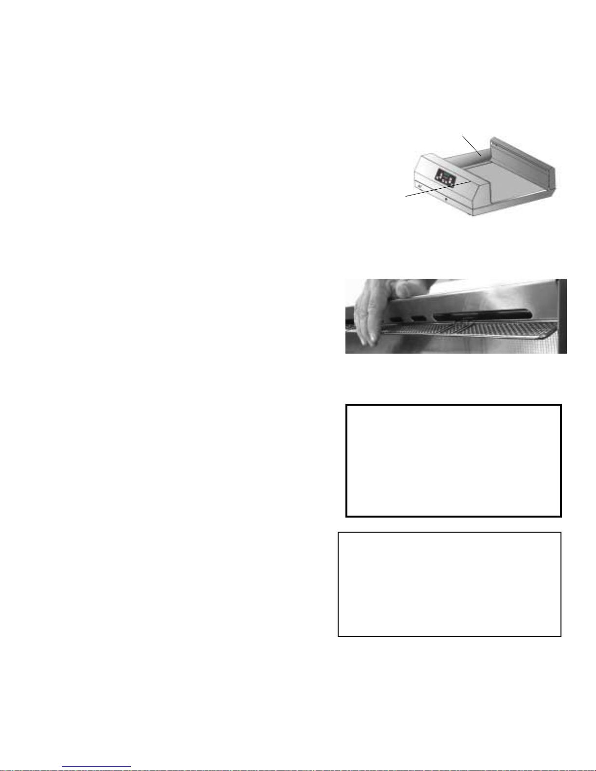
INSTALL OPTIONAL BURGER BUMPER (Units built before 10/98)
The burger bumper may be placed on either side of the
HLZ to prevent pass through of product. Burger bumpers
are provided by the KES. See figure 1.
INSTALL FILTER SCREEN (Units built after 10/98)
The filter screen is design to prevent debris from entering
the Computer Cowl Assembly and clogging the blower
assembly. Simply fit the part on to the vent opening of the
computer cowl assembly. The filter screen will snap into
position. If equipped with an optional holding screw,
tighten screw to pull the filter screen snug into position.
POWER REQUIREMENTS:
•Voltage – Two models are available: 208 VAC and 240 VAC*
•Frequency - 60 Hz
•Single Phase
•20 amp Service
5. OPERATION
1. Plug the unit into the power source.*
2. See “HLZ COMPUTER OPERATION AND
PROGRAMMING, Section 7” for proper setup and
operation of the computer.
3. Place product in the HLZ in accordance with the
restaurant’s established procedures.
4. CLOSING - When closing the store, remove all product from the HLZ and perform daily preventive
maintenance in accordance with the MRC. Turn the computer OFF.
THIS APPLIANCE IS EQUIPPED WITH
A
GROUNDING PLUG FOR YOUR
PROTECTION AGAINST SHOCK
HAZARD AND MUST BE PLUGGED INTO
A PROPERLY GROUNDED
RECEPTACLE. DO NOT CUT OR
REMOVE THE GROUNDING PRONG
FROM THIS PLUG.
Figure 1
Optional Burger Bumper
Installed (unit built before 10/98)
Compute
r
Cowl
* If the 240 VAC model is operated on
208 VAC, the unit will heat slowly an
d
may not reach maximum temperature. I
f
the 208 VAC model is operated on 24
0
VAC, component damage is probable.
To ensure proper operation, the powe
r
source should match the voltage on the
rating plate on the bottom of the HLZ.
The filter screen snaps into place on
rear of the air-intake tower.

Frymaster L.L.C., 8700 Line Avenue 71106, P.O. Box 51000, Shreveport, Louisiana 71135-1000
318-865-1711 FAX 318-862-2394
Printed in the United States Service Hotline Page 4
1-800-24-FRYER
6. HLZ MODEL/COMPONENT IDENTIFICATION
Heated air flows
from the air
heater/blower
and heat rises
from the heater
plate.
Heater Plate
Calibration
Socket
Air Heate
r
Calibration
Socket HLZ Computer
Heater
Plate/Landing
Zone
Power Cord
Blower Assembly
Air Heater
Heater Plate
A look at the flow of
heated air around the HLZ
Heater plate

Frymaster L.L.C., 8700 Line Avenue 71106, P.O. Box 51000, Shreveport, Louisiana 71135-1000
318-865-1711 FAX 318-862-2394
Printed in the United States Service Hotline Page 5
1-800-24-FRYER
7. HLZ COMPUTER OPERATION AND PROGRAMMING
7. 1 Programming Temperature
You are able to program the setpoint temperature of both the air heater and the heater plate
via the computer interface. The heater plate can be set between 140°F to 180°F -- the factory
default is set to the McDonald’s standard of 160°F. The air heater can be set between 170°F
to 240°F -- the factory default is set to the McDonald’s standard of 220°F. If the factory default
temperature settings are acceptable, skip to Section 7.20, Page 6.
Ensure that the HLZ computer is in the OFF position (nothing in the display).
Press the check switch and enter the code (1,2,3,3). The numerals in the upper right-hand
corner represent the key number.
Press , then , , , in order
The display will read SET and the LEDs on both the Heater Plate Switch (1) and the Air Heater
Switch (4) will light. Press the switch that corresponds to the heater you wish to program.
Heater Plate
Temperature
Switch (1)
ON/OFF Switch
Down Switch (2) Up Switch (3)
Check or
Pro
g
ram Switch
A
ir Heater
Temperature
Switch
(
4
)
Displa
y

Frymaster L.L.C., 8700 Line Avenue 71106, P.O. Box 51000, Shreveport, Louisiana 71135-1000
318-865-1711 FAX 318-862-2394
Printed in the United States Service Hotline Page 6
1-800-24-FRYER
Display reads
SET
SETSET
SET
,
and LED’s light.
Press to program the heater plate or to
program the air heater.
Press the Up and Down Arrow Keys to achieve the desired set-point temperature, then press
the Check Switch once. Both heater LEDs will again light.
Press or to get desired setpoint, then press
to lock the temperature in.
If you are finished with programming both heaters, press the Check Switch again to store the
programmed setpoints and exit the programming mode OR to change the setpoint
temperature for the other heater, press the corresponding Heater Switch (1 or 4).
Program as described in Step 4.
When finished, press again to exit programming
mode. To change the other heater, press to
program the heater plate or to program the air
heater, then go to Step 4 for instructions.
7.2 Operation
1. Press the ON/OFF switch to the ON position (the display will light and cycle through an
initialization sequence). The display will read –LO- until the air heater and heater plate are
within 15°F of setpoint. It will take approximately 10 minutes for the HLZ to achieve
operating temperature.

Frymaster L.L.C., 8700 Line Avenue 71106, P.O. Box 51000, Shreveport, Louisiana 71135-1000
318-865-1711 FAX 318-862-2394
Printed in the United States Service Hotline Page 7
1-800-24-FRYER
Press to turn on the computer.
The display will read
— L O —
— L O —— L O —
— L O —
until both heaters are
within 15
°
F of setpoint
NOTE: A small LED will light in a specific location in the display when either the heater plate or
air heater is energized.
When the HLZ is ready for operation, the display reads REdY (ready). Place product in the
HLZ in accordance with the restaurant’s established procedures.
NOTE: To check the actual temperature of a heater, press the corresponding Temperature
Switch once. To check the setpoint temperature of a heater, press the switch twice (an
indicator will light when the setpoint is displayed).
R E y
Heater Plate
Air Heate
r
2 2 0 Setpoint
Temperature
d
¡

Frymaster L.L.C., 8700 Line Avenue 71106, P.O. Box 51000, Shreveport, Louisiana 71135-1000
318-865-1711 FAX 318-862-2394
Printed in the United States Service Hotline Page 8
1-800-24-FRYER
8. HLZ Series Operator Troubleshooting
The HLZ does not
function properly.
Press the ON/OFF
switch.
Does the
computer power
up?
Computer is
functioning.
Does air blow
out of the cowl
assembly?
The blower is
operational.
Run the unit for 20 minutes
before continuing with
troubleshooting.
Observe the
computer display.
Go to next page and
continue at the top of
the flow chart.
The blower, latching
relay, or solid state
relays need service.
Is the power cord
plugged into the proper
voltage outlet?
Check wall circuit
breaker to see if it
has tripped.
If circuit breaker
has tripped, reset
the breaker.
Plug power cord
into proper outlet.
Press ON/OFF
switch once.
Does the
computer come
on?
Low voltage
transformer, fuse, or
computer is faulty.
Call your authorized
Frymaster servicer.
Yes
No
Yes
No
Yes
No
Yes
No

Frymaster L.L.C., 8700 Line Avenue 71106, P.O. Box 51000, Shreveport, Louisiana 71135-1000
318-865-1711 FAX 318-862-2394
Printed in the United States Service Hotline Page 9
1-800-24-FRYER
The HLZ has been
powered up and has
been running for at
least 20 minutes.
The computer
display reads:
PROB
One of the RTD
probes has
failed.
Press the plate heater
temp switch once to
see actual temp.
Is the plate
heater temp within +/-
15°F of programmed
temp?
Heater plate
RTD is good.
Press air heater
temp switch once
to see actual temp.
Is the air
heater temp within +/-
25°F of programmed
temp?
Computer may
be faulty. Air heater RTD
probe is faulty.
Heater plate
RTD is faulty.
Contact your
authorized
Frymaster servicer.
HI
Press the plate heater
temp switch once to
see actual temp.
Is the plate
heater temp within +/-
15°F of programmed
temp?
Plate heater, plate
heater relay, or RTD
are faulty.
LO
Press the air heater
temp switch once to
see actual temp.
Is the air
heater temp within +/-
25°F of programmed
temp?
Air heater, air
heater relay, or
RTD are faulty.
Contact your
authorized
Frymaster servicer.
REdY
Unit has
reached
setpoint.
Do you feel hot
air coming out of the cowl
assembly?
Air heater is
good.
Press the heater plate
temp switch once to
read actual temp.
Press the heater plate
temp switch a second
time to read setpoint.
Is the actual
temp within +/- 15°F of
setpoint?
Heater plate is
good.
Your HLZ is
ready for use.
Yes
No
Yes
No
No
Yes
No
Yes
No
Yes
No
Yes

Frymaster L.L.C., 8700 Line Avenue 71106, P.O. Box 51000, Shreveport, Louisiana 71135-1000
318-865-1711 FAX 318-862-2394
Printed in the United States Service Hotline Page 10
1-800-24-FRYER
9. SERVICE INFORMATION
9.1 PARTS LIST
This parts list is correlated with the HLZ interior view found in section 9-2.
Item
#Description Part
Number
1Transformer, 208V/240V/12V
807-0979
2A Air Heater, 208V only
807-2945
2B Air Heater, 240V only
807-3011
3Shield, HLZ Heater
900-8073
4Air RTD Probe
807-3036
5Bracket, RTD/Thermocouple
900-8086
6Delivery Air Back W/A
823-2741
7Air Thermocouple
807-3043
8A HLZ 22 Plate, Heater with RTD
and Thermocouple, 208V/240V
(22”x15.5”)
806-9238
8B HLZ 18 Plate, Heater with RTD
and Thermocouple, 208/240V
(22”x12”)
806-9239
9Plug Assembly, Computer
806-9146
10 Relay, Solid State Service Kit
826-1508
11 Relay, Latching
807-3021
12 Blower, 208V/240V
807-2953
Item # Description Part
Number
13 Fuse Block
807-2820
14 Fuse, 20A
807-2819
15 Cord Set, Twist Lock, HLZ
807-3020
Not Shown RTV#108 Silicone Rubber
811-0511
Not Shown Gasket, HLZ Plate/Cowl
816-0418
Not Shown Filter Screen
810-1724
Not Shown Acrylic Tape, Double-
Sided
811-0953
Not Shown Computer Assembly, HLZ
806-9247
Not Shown Cowl Assembly
823-2745
Not Shown Cowl Tinnerman Clips
809-0448
Not Shown Front Delivery Air W/A
823-2742
Not Shown Lug, Grounding 14 GA
807-2972
Not Shown Pad, HLZ Leg
816-0410
* Note: Burger Bumpers are not used on units built after
10/98.
9.2 Interior view of an HLZ (Cowl Assembly removed)
Blower assembly
Fuses
Relays
•Air RTD Probe
•Air Thermocouple

Frymaster L.L.C., 8700 Line Avenue 71106, P.O. Box 51000, Shreveport, Louisiana 71135-1000
318-865-1711 FAX 318-862-2394
Printed in the United States Service Hotline Page 11
1-800-24-FRYER
9.3 Procedures
1. Accessing the interior of the HLZ (Set up for
testing):
a. Disconnect power cord from outlet.
b. Turn unit on its side. Remove the five access
screws located on the bottom of the unit.
c. Then set the unit back down on its base. Place
paper towels on the heater plate to protect it from
scratching. Remove the cowl assembly and lay the
cowl on the heater plate while troubleshooting.
2. Replacing Solid State Relays:
a. Avoid miswiring. Examine the terminals carefully and take notes to avoid miswiring.
b. Remove the plate holding the relay assembly. The nuts holding the relays in place are
easier to reach with the assembly out of the unit.
c. Remove the two nuts holding relays to plate.
d. Apply heat sink compound and install new relay.
e. Reverse this procedure to reinstall.
The relays are
best replaced
by removing
the plate that
holds them in
place. Two
5/16 nuts hold
the plate in
place.
12
34
240VAC 12A
12
34
240VAC 12A
Heater plate
relay
Air heater
relay
Heater Plate Front of HLZ
The cowl assembly is held on by
five screws, which are removed
from the bottom of the unit.

Frymaster L.L.C., 8700 Line Avenue 71106, P.O. Box 51000, Shreveport, Louisiana 71135-1000
318-865-1711 FAX 318-862-2394
Printed in the United States Service Hotline Page 12
1-800-24-FRYER
3. Opening the Air Delivery Tower:
a. The air thermocouple and air RTD are
located in the air delivery tower. To
access them, the front air delivery
assembly must be removed.
b. Insert a 5/16” nut driver through the
front air delivery assembly access
holes and turn the nuts
counterclockwise to loosen. Do not
remove the nuts. Grab the bottom
flange of the front air delivery, push
upwards and pull towards you. Be
careful, there are two tabs on the front air delivery
bottom that must clear the heater plate to allow
removal of the front air delivery.
4. Replacing Air Thermocouple and Air
RTD Probe:
a. Follow procedures in section 9.3.2 to
access the Air Delivery tower
components.
b. Cut old lead wires close to the faulty air
thermocouple or Air RTD Probe.
Disconnect lead wires at the test plug.
Leave lead wires in place for now.
c. Remove the faulty Air Thermocouple or Air RTD Probe from the bracket.
d. Install the replacement Air Thermocouple or Air RTD Probe into the bracket.
e. Attach the new lead wires to the old lead wires on the Air Thermocouple or Air RTD
Probe on the bracket-side of unit. Grasp the old leads at the test plug and gently pull the
leads towards you.
f. Once the new lead wires have been pulled through, disconnect the old lead wires, and
attach the new leads to the test plug.
g. Go to step 9.3.2 and reassemble the air delivery tower.
Components in the rear tower are
accessed by loosening two nuts,
one under each end of the
overhang.
A
ir Thermocouple Air RTD Probe

Frymaster L.L.C., 8700 Line Avenue 71106, P.O. Box 51000, Shreveport, Louisiana 71135-1000
318-865-1711 FAX 318-862-2394
Printed in the United States Service Hotline Page 13
1-800-24-FRYER
5. Accessing the Plate and Air Heaters:
a. Use the following method to remove the plate heater
assembly or access the compartment underneath the
plate heater.
b. Remove the cowl assembly per step 9.3.1.
c. Then remove the air delivery assembly following steps 9.3.2a and 9.3.2b.
d. Insert a thin, sharp knife, i.e. Exacto-type, between the heater plate and the HLZ
chassis. Carefully cut the silicon adhesive
between the heater plate and the chassis.
e. Lift the heater plate by prying up one end of
the heater plate away from the HLZ chassis.
The plate is held in place by an acrylic tape.
It will be difficult to break the bond between
the heater plate and chassis.
f. Remove acrylic tape from the heater plate
and frame to prevent rebounding while
servicing.
g. When reinstalling the heater plate,
apply new acrylic tape to the HLZ
chassis first. Then position the
heater plate standing on its side
against the back air delivery
assembly. The heater plate leads
should be coming off the “top” edge of
the heater plate.
h. Once the heater plate is aligned
properly with the HLZ chassis, gently
lower the heater plate until the plate end with the lead wires is approximately 2 inches
from the chassis. Feed the leads through the opening in the chassis wall.
i. Finish lowering the heater plate into place and connect the heater plate lead wires.
A
fter cutting the acrylic adhesive
between the heater plate and the HLZ
chassis, use a screwdriver to gently
lift the heater
p
late.
Gently lift the heater plate, which may still
be stuck to the adhesive. Apply new acrylic
tape to the chassis before reinstalling the
heater plate.
NOTE: A hot platen is
easier to remove. The
heat makes the
adhesive holding the
platen in place more
pliable.

Frymaster L.L.C., 8700 Line Avenue 71106, P.O. Box 51000, Shreveport, Louisiana 71135-1000
318-865-1711 FAX 318-862-2394
Printed in the United States Service Hotline Page 14
1-800-24-FRYER
6. Reinstalling the Cowl Assembly and Air Delivery Assembly/Gasket Installation:
a. Cowl Assembly:
1. Clean surface area thoroughly.
2. Remove any old adhesive.
3. Apply a new gasket to bottom edge of
the cowl assembly.
4. Test fit the cowl assembly to see if a
gap is visible once the cowl
assembly is properly seated. If a
gap remains, apply a second gasket
to create a better seal.
5. Plug in the computer harness and
reinstall the cowl assembly .
b. Air Delivery Tower Assembly:
1. Clean surface area thoroughly.
2. Remove any old adhesive.
3. Apply new gasket along bottom edge of the front air delivery panel.
4. Test fit the air delivery assembly to see if a gap is visible once the assembly is
properly seated. If a gap remains, apply a second gasket to create a better seal.
5. Make sure the brackets on the back-side of the front air delivery assembly slide up
and under the nuts on the back air delivery mounting screws (see figure 9-8). Once
the front air delivery tabs clear the heater plate and the front air delivery is seated,
tighten the mounting screws to pull the front air delivery flush against the back air
delivery assembly. An air seal is created between the lower sections of the front air
delivery and back air delivery assemblies. This seal forces the heated air up the rear
and then down the front-side of the front air delivery assembly. After reinstalling the
air delivery tower, reseal around the heater plate with RTV #108 silicone rubber
compound, PN 811-0511.
Apply gasket or sealant along this edge

Frymaster L.L.C., 8700 Line Avenue 71106, P.O. Box 51000, Shreveport, Louisiana 71135-1000
318-865-1711 FAX 318-862-2394
Printed in the United States Service Hotline Page 15
1-800-24-FRYER
9.4 Troubleshooting Flow Charts:
1. Follow the flowchart on pages 15 - 18 to help locate and troubleshoot the most likely
encountered problems. The flowchart will give possible solutions/corrective actions to be
taken.
2. To use the flowchart, start at the top of the diagram. Follow each step in sequence. If the
answer to a question is “yes”, proceed downward to the next step. If the answer is “no”,
follow the arrow to the right to the possible solutions/corrective action boxes.
3. The left box offers possible solutions. The right box gives the corresponding test procedure
to verify the possible solution or corrective action. Test procedures are found on pages 16
– 18.
WARNING!
INSPECTION, TESTING, AND REPAIR
OF ELECTRICAL EQUIPMENT SHOULD
BE PERFORMED BY QUALIFIED
PERSONNEL.
Notes: * REdY, HI, or PROB may also appear. REdY
indicates the temperature is near set temp. HI
indicates the temperature is above set temp. PROB
indicates a defective probe circuit (air RTD or heate
r
RTD).
** STD = Standard troubleshooting test.
N/A = No a
pp
licable test.
YES
Unit powers up
and display reads
LO
Push ON/OFF
switch.
Plug in to power
source.
Set up for test per
section 9.3.1.
Follow each step
in sequence.
1. Incorrect or no voltage
applied.
2. Tripped wall circuit breaker.
3. Blown 20A fuse.
4. Transformer has failed.
5. Computer is faulty.
6. Wiring connection is faulty.
NO
1. STD **
2. STD
3. STD
4. Test A
5. Test B
6. STD
Go to page 16 and
continue.

Frymaster L.L.C., 8700 Line Avenue 71106, P.O. Box 51000, Shreveport, Louisiana 71135-1000
318-865-1711 FAX 318-862-2394
Printed in the United States Service Hotline Page 16
1-800-24-FRYER
A
llow the heaters to
heat for approximately
3 minutes.
NO 1. Latching relay has failed.
2. Blower is faulty.
3. Computer has failed.
4. Wiring connection is faulty.
5. Foreign object is stalling
the blower.
1. Test E
2. Test F
3. Test B
4. STD
5. N/A
1. Heater Plate (RTD) is faulty.
2. Computer has failed.
3. Wiring connection is faulty.
1. Test C
2. N/A
3. STD
NO
YES
Does LED light come
on indicating unit is
calling for heat from
the plate heater?
1. Air Temp Probe is faulty.
2. Computer has failed.
3. Wiring connection is faulty.
1. Test D
2. N/A **
3. STD
NO
Does LED light
come on indicating unit
is calling for heat from
the air heater?
Continued from
p
a
g
e 15.
Go to page 17.
Does air blow
out of the cowl
assembl
y
?
YES
YES

Frymaster L.L.C., 8700 Line Avenue 71106, P.O. Box 51000, Shreveport, Louisiana 71135-1000
318-865-1711 FAX 318-862-2394
Printed in the United States Service Hotline Page 17
1-800-24-FRYER
After 3 minutes, does the
air heater light change
from being on continuously
to flickering?
YES Is air temp
within 25°F of
set
p
oint?
YES
Computer
is faulty.
NO
1. Air heater has
failed.
2. Air heater relay is
faulty.
3. Air RTD is faulty.
4. Computer has
failed.
5. Wiring connection
is faulty.
1. Test G
2. Test H
3. Test D
4. Test B
5. STD
NO Push button #4 once to
check actual air temp, then
push again to check set
point.
After an additional 7
minutes, does “REdY”
appear in the display
indicating heater is
near set point?
YES
Push button #1 once to check actual plate
temp, then push again to check set point.
Is plate temp
within 15°F of
set point?
YES
Computer
is faulty.
1. Plate heater has
failed.
2. Plate heater relay
is faulty.
3. Computer has
failed.
4. Wiring connection
is faulty.
1. Test C
2. Test H
3. Test B
4. STD
Operation
is normal.
NO
NO
A
ir temp is near set point.
Continued from page 16.

Frymaster L.L.C., 8700 Line Avenue 71106, P.O. Box 51000, Shreveport, Louisiana 71135-1000
318-865-1711 FAX 318-862-2394
Printed in the United States Service Hotline Page 18
1-800-24-FRYER
9.5 Component Test Procedures
TEST A - TRANSFORMER
1. Set up HLZ series for testing per 9.3.1.
a. Remove one wire from each side of transformer.
b. Measure each side for resistance.
Correct readings are:
1. 208VAC HLZ series: line side – 200 (±10) ohms.
2. 240VAC HLZ series: line side – 235 (±10) ohms.
c.
3. 208VAC and 240VAC HLZ series: load side – 1.1 (±0.2) ohms (12VAC side).
d. If resistances are incorrect, replace the transformer.
2.
e. Reconnect wires.
a. Plug HLZ in. Check for 208VAC (or 240VAC) across the input (line) terminals of the
transformer.
b. Test for approximately 14VAC across the output (load) terminals of the transformer.
3.
c. If 208/240VAC is applied and output voltage is less than 10VAC, the transformer is
defective.
TEST B - COMPUTER
Input Power:
1. Set up HLZ series for testing per 9.3.1.
2. Plug HLZ in.
3. With connector unplugged, check for approximately 14 VAC between pins 1 and 3 on the
15-pin computer plug. (See figure 9-10, page 20)
4. If voltage is low or missing, check transformer and wiring.
Output Power:
1. Plug connector into computer.
2. Turn computer on.
3. Check for approximately 10VDC from the “+” terminal (red wire) on the heater plate relay to
ground.
4. No output voltage indicates a faulty computer.
DANGER!
USE EXTREME CARE DURING
ELECTRICAL CIRCUIT TESTS. LIVE
CIRCUITS WILL BE EXPOSED.
This manual suits for next models
1
Table of contents
Other Frymaster Food Warmer manuals

Frymaster
Frymaster Rethermalizer FGP55 User manual

Frymaster
Frymaster UHC-P 2 Service manual

Frymaster
Frymaster UHC-P 2-yuva User manual

Frymaster
Frymaster Gas Rethermalizers FBR18 Series User manual

Frymaster
Frymaster Heated Landing Zone HLZ 18 User manual

Frymaster
Frymaster UHC-HD Guide

Frymaster
Frymaster UHC-P Building instructions

Frymaster
Frymaster FWH-1 User manual

Frymaster
Frymaster Enodis Rod-style Food Warmer Bulb-style Food Warmer Cafeteria-style Dump Pan Scoop-style Dump... User manual

Frymaster
Frymaster Heated Landing Zone HLZ User manual