FSI PT-4000H User manual

PT-4000H
Operating Instructions
MKT-02 1/13

PT-4000H Rivet Capacity
The PT-4000H-1 pulls most all pull style blind rivets including CherryMax® and Cherry “A”
Max® thru 1/4” diameter in all materials and Blind Bolts and Maxibolts® thru 1/4” diameter.
Equipment/Accessories
Wrench: SW 12 (covers nosepiece compartment)
Suspension Loop: Flips open from housing
Battery: Quick Charge/ 12 Volt DC
Technical
Data
Weight: 4.85 lbs (with battery)
Stroke: 0.787”
Drive Unit: 14.4 V direct current motor
Traction Power: 5,000 lbs.
Nosepiece Table
Rivet Diameter Rivet Body Material *Rivets Per Charge Nosepiece Part No.
3/32” Aluminum 1,900 F140
1/8” Aluminum 1,300 F159
1/8” Steel 1,100 F159
1/8” Stainless Steel 1,000 F159
5/32” Aluminum 1,000 F143
5/32” Steel 900 F143
5/32” Stainless Steel 800 F143
3/16” Aluminum 700 F143
3/16” Steel 500 F143
3/16” Stainless Steel 400 F143
1/4” Stainless Steel 90 F142
* Rivets per battery charge based on Mil-R-24243 style blind rivets in maximum grip condition
1.

Attention: Do not cover or stick anything into the vent holes.
Starting Procedure
Install fully charged battery into housing. Select proper nosepiece (see page 2) and screw into
head.
Operating Procedure
Pushing the trigger starts the operation. When releasing the trigger, the jaw mechanism returns to
the start position automatically.
Eject the spent mandrel into the mandrel container by tilting the tool backward, or through the
nosepiece by tilting tool forward.
The riveting tool is equipped with overload protection. In case if an overload, the operation will
be stopped and the red light goes on. If that happens, release the trigger and the mechanism will
return to the start position.
The battery will deliver uniform power for tool operation until depleted to the last 2-3 rivets of
charge capacity. It is designed to have the jaw mechanism return to the starting position when the
trigger has been released.
Maintenance
The maintenance of the riveting tool is limited to the complete jaw mechanism and the included
wearing parts.
Remove the battery (#40) from the tool housing.
Warranty
There is a 12 month warranty from the day of delivery on the PT-4000H-1. Damages caused by
common wearing, overloading or improper usage or handling are excluded from the warranty.
Damages caused by material or manufacturing faults will be covered by this warranty and will be
repaired or replaced at no cost. Claims can only be accepted if the complete riveting tool, fully
assembled, is returned to the distributor or FSI.
2.

Charger Battery
Input Voltage: 110 V/60 Hz Rated Voltage: 12 VDC
Output Voltage: 12 VDC Number of Cells: 10 Pieces
Recharge Time: Approx. 1 hour Cell Construction: Nickel-Metal with
Weights: 2.6 lbs. Overcharge protection
Capacity: 3.2 amp hour
Weight: 1.4 lbs
Recharging Procedure
Take charger out of steel case and connect to power line.
Make sure the voltage is in accordance with the label!
The battery must be installed correctly (positive pole to positive pole) with minimal force into
the charger. The quick recharging procedure is automatically started and indicated by red light.
After approximately 1 hour the charging procedure is finished and the charger switches to
trickle charge, indicate by a green light.
Place only cool batteries into the charger in order to obtain a full battery recharge.
Battery Handling
The battery is rechargeable up to 1000 times and reaches its full power only after several
recharging's. Do not discharge the battery completely. Recharge is not used for an extended
period.
Substantially reduced operating time of battery after a proper recharge indicates the battery
must be replaced. Keep battery in a cool and dry place, with temperature not to exceed (122 F).
Environmental Protection
If batteries have to be replaced, the following instructions should be followed:
Return used batteries to your supplier or FSI for recycling. Under no circumstances should
nickel-metal batteries be discarded as normal waste which might be burned or exposed to
ground water.
3.
Battery / Charger Technical Data

Blind Rivet Cannot be Set
Causes Remedy
Depleted battery charge Recharge, if necessary replace
Jaws dirty or worn Clean and lubricate or replace
Jaw pusher spring weak Tighten
When trigger is pressed, no function Replace
(red indicator light shows)
Troubleshooting
No Spent Mandrel Discharge
Causes Remedy
Wrong nosepiece Exchange according to page 2
Nosepiece worn Replace
Mandrel jammed in jaws Loosen the mandrel, clean and lubricate the
jaws or replace
Head Dirty inside Clean
Spent mandrel container filled Remove and empty
Passage clogged Remove clogged mandrels and check for free
ejection
Red Light Indicated Faults
A) When trigger is pressed
Causes Remedy
Overheating of electronic control Allow too to cool to ambient temperature
B) While pulling the rivet
Causes Remedy
Overloading Check working capacity
Overheating of electronic control Allow tool to cool to ambient temperature
Depleted battery charge Recharge or replace
C) After releasing the trigger
Causes Remedy
Jaw mechanism is not reaching the front Tighten jaw mechanism
position 4.

Maintenance Instructions
General Notes
Warranty repairs are carried out by the manufacturer only. Repairs outside the warranty period
should only be carried out by trained personnel. The following instructions must be strictly
adhered to, as assembly or adjustment errors may cause major damage to the PT-4000H-1.
Repair Tools & Lubricant
For repair of the PT-4000H-1, the following should be available:
Screw Driver Torx T 20
Hexagonal Wrench SW 2.5 mm
Open End Wrenches
Adjustable Wrench
Lubricating Grease
Dismantling the PT-4000H-1
Remove battery (#40) from the tool. Unscrew spent mandrel container (#39). Remove housing
screw (3 pcs. #32 & 5 pcs. of #33) with screw driver Torx T 20.
Take off hand guard (#31). Take off top of tool housing (#1) and pull off the red and blue
connecting wires from the electronic control (#26). Unscrew electronic control (#26) using
screw driver Torx T 20.
Unscrew magnet holder (#27) using the hexagonal wrench SW 2.5mm. Take out electronic
control (#26) and magnet holder (#27). Take out motor (#25).
ATTENTION: Reassembly Tip: Note how connecting wires to the motor are
laid out in the tool housing!
5.

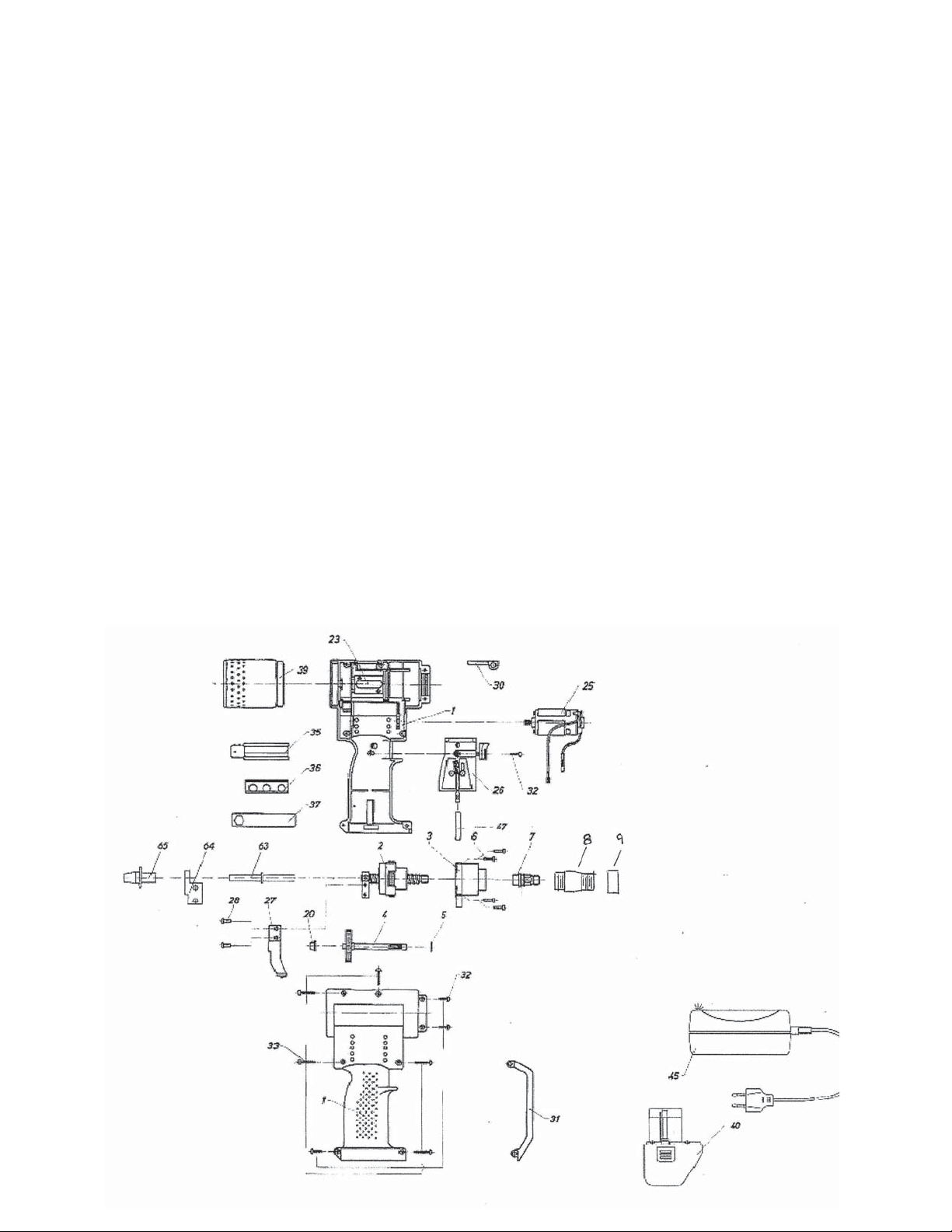
Assembly & Stroke Adjustment
Assembly of Drive System (#42) Slip drive bearing (#3) over ball screw drive (#2) and put
pinion shaft (#4) together with snap ring (#5) in bearing place.
Attention: Before screwing ball screw drive (#2) and drive bearing (#3) together, make sure
the locating marking “B” of the bearing disk inside the ball screw drive (#2) is placed opposite
the pinion shaft (#4). See Parts Drawing.
Assemble this entire unit together with the 4 screws (#6) using hexagonal wrench SW 2.5mm.
Screw jaw housing coupler (#7) with scraper ring (#8) onto ball screw using open end wrench
SW 14mm.
Put jaw pusher spring (#9) and jaw pusher (#10) onto jaw housing coupler (#7). Place the jaws
(#11) in jaw housing (#12) and screw this onto jaw housing coupler (#7) using open end wrench
SW 17mm.
Screw head (#13) on using open end wrench SW 27mm.
Assembly of the PT-4000H-1
The sub-assemblies and other parts should be put into tool housing half (#1) containing the
nosepiece bracket as follows:
To install drive system (#42), slip the bushing (#20) onto the shorter end of the pinion shaft (#4)
while ensuring that the snap ring (#5) in pressed to the gear.
To insert the tube (#22), the longer end of the tube must be inserted into the ball screw, while
the collar of the tube must be inserted into the provided recess of the tool housing.
To place the motor connecting wire, the red wire should be bent downwards at the soldering tag
towards the blue wire, then bent again to be parallel with the blue wire.
To install motor (#25), the two connecting wires are to be places side by aide around the first
guiding stud of the tool housing and behind the middle guiding studs. The wires should then be
brought up in front of the third guiding stud.
The electronic control unit (#26) should be installed by putting it on the stud inside the tool
housing and then fastened with the housing screw (#32). Click magnet holder (#27) in the
guiding slot of the electronic control (#26).
Fasten other end of magnet holder (#27) to ball screw drive (#2) with magnet holder screws
(#28) together with two spring lock washers (#29) using the hexagonal screw drive SW 2.5.
For later stroke adjustment, do not tighten the screws. Plug the two blue connecting wires of
motor (#25) and electronic control until (#26) together.
DO NOT CONNECT RED WIRE YET!!
6.

Stroke Adjustment
Turn gear of pinion shaft until distance “A” measures 0.118” -See Parts Drawing. Then insert
battery (#40) correctly in tool housing.
ATTENTION: Positive pole of battery (#40) must be at top to avoid
damage of electronic control unit (#26).
While trigger is pressed, magnet holder (#27) must be adjusted in slot of electronic control until
red indicator light goes on. After releasing trigger, the two magnet holder screws (#28) must be
tightened. NOW connect red wire to electronic control (#26).
ATTENTION: Both connecting wires must be places around guiding stud on
electronic control (#26) in such a way to keep slot free
for movement of magnet holder (#27).
Preliminary Motor Test: Motor (#25) is be carefully held down at both ends. Make sure to
allow room for magnet holder to move back and forth. Pull trigger to move jaw mechanism
about .200 to .400 inches, and release trigger.
Check distance “A” (See Parts Drawing). It must be 0.039” - 0.051”
If distance “A” gap is below 0.039”, magnet holder (#27) should be moved carefully to
the right after loosening the to screws (#28) in order to obtain .039 to .051 gap.
If distance “A” gap is larger that 0.051”, magnet holder must be moved to the left
accordingly. After tightening the screws (#28), repeat test and recheck distance “A”.
Take battery (#40) out of toll housing.
Finishing
Lubricate gear teeth with lubricating grease. Insert suspension loop (#30). Insert hand guard
(#31). Replace second half of tool housing.
Tighten both halves of tool housing (#1) together with the five housing screws (#33) and the
three housing screws (#32) using screw driver Torx T 20.
7.

Safety Notes
The PT-4000H-1 has been designed and manufactured in accordance with the applicable safe-
ty regulations. If the PT-4000H-1 is being used for the intended purpose in accordance with
instructions and normal safety measures, there is no danger involved during operation.
WARNING!
Never operate the PT-4000H-1 without placing the blind rivet
in proper hole of the work piece or material.
The rivet could be propelled from the tool.
Avoid pointing the tool at anyone during operation.
The spent mandrel container (#39) must always be firmly screwed into place on the tool
during operation. Do not plug or cover vent holes in tool housing an any time.
Repairs should be carried out by trained personnel only. Otherwise, return PT-4000H-1 to
supplier or to FSI.
Do not operate the PT-4000H-1 and the Battery Charger in an environment allowing exposure
to moisture, combustible fluids or gases.
Avoid damage to cord and plug of charger. Inspect regularly for any damage. Ensure that the
battery is properly secured in the tool housing.
Take the charger out of steel case when recharging the battery. Place the battery in the correct
position (+pole to +pole) and do not force it into the charger.
Always remove the battery before servicing / repairing the PT-4000H-1.
Do not discard batteries into water or fire as danger of explosion exists. Any used battery be
disposed of in accordance with environmental regulations.
Do not use the PT-4000H-1 for any function other than riveting, especially not as a hammer.
8.

Item Part No. Description Item Part No. Description
1 F3014 Tool Housing, complete 36 F3091 Nosepiece Holder
2 F3189 Ball screw drive, assembled 37 F3834 Nosepiece Wrench
3 F3185 Drive bearing, complete 39 F3282 Spent Mandrel Canister
4 F3193 Power transfer gear 40 F-3001A 12v Battery Pack
5 F3753 Snap ring 45 F-4000A Battery Charger, 110v
6 F3982 Screw 45A F-4000A/220 Battery Charger, 220v
7 F127672 Draw Bolt 63 F3286 Spent Mandrel Tube
8 F127673 Nose Adapter 64 F3308 Brace
9 F111795 Jam Nut 65 F3316 Pin Tail Guide
20 F3893 Bushing
23 F3737 Guide
25 F3103 Motor, Complete
26 F3850-1 E-Control
27 F3266 Magnet Holder
28 F3990 Magnet Holder Screws
30 F3559-1 Suspension Loop
31 F3540 Handle Guard
32 F3032 Housing Screw
33 F3024 Housing Screw, Short
35 F3030 Nosepiece Bracket
10.
Table of contents