FTS DigiTemp User manual

1.800.548.4264
www.ftshydrology.com
700-DigiTemp –Rev. 1.0, 24 Nov 2011
DigiTemp
SDI-12 Submersible Digital
Temperature Sensor
User Manual

Contact information
FTS
1065 Henry Eng Place
Victoria, B.C., V9B 6B2
CANADA
www.ftshydrology.com
Toll-free
1-800-548-4264
Local
250-478-5561
Technical support
support.ftshydrology.com

Revision History
Date
Person
Description
24 Nov 2011
RG
First released version
28 Nov 2011
RG
Late corrections

Table of contents
Contact information...............................................................................................................................ii
Chapter 1 Operation........................................................................................................................5
1.1 General description ...........................................................................................................................................................6
1.2 Installation.............................................................................................................................................................................6
1.3 Connection............................................................................................................................................................................7
1.4 Operation...............................................................................................................................................................................7
1.5 Configuration .......................................................................................................................................................................7
1.6 Calibration and maintenance ........................................................................................................................................7
Chapter 2 SDI Commands................................................................................................................8
2.1 Notation for SDI commands...........................................................................................................................................9
2.2 Commands recognized by DigiTemp.........................................................................................................................9
2.3 General SDI commands....................................................................................................................................................9
2.4 SDI Data commands .......................................................................................................................................................10
2.5 Description of measured values ................................................................................................................................12
Chapter 3 Technical specifications .............................................................................................. 13

Chapter 1 Operation
Chapter contents
1.1 General description ...........................................................................................................................................................6
1.2 Installation ............................................................................................................................................................................6
1.3 Connection ...........................................................................................................................................................................7
1.4 Operation ..............................................................................................................................................................................7
1.5 Configuration.......................................................................................................................................................................7
1.6 Calibration and maintenance ........................................................................................................................................7

DigiTemp User Manual Chapter 1 Operation
page 6
1.1 General description
The FTS DigiTemp Submersible Temperature Sensor is simple, compact, rugged SDI-12 device that measures
temperature of water or soil. The DigiTemp is extremely simple to use: it needs absolutely no configuration in
most applications, and it returns measured temperatures in both degrees Celsius and degrees Fahrenheit. It is
accurate to 0.2 °C over a temperature range of -5 °C to +45 °C.
The FTS DigiTemp consists of a thermistor sensing element connected to a microcontroller unit that processes
the thermistor resistance into a temperature value and communicates with the data collection platform using
the SDI-12 protocol. The data collection platform requests measurements by sending commands to the
DigiTemp.
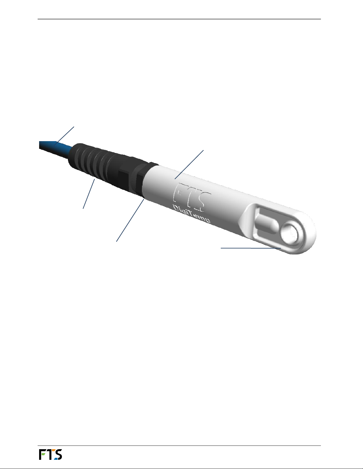
Figure 1-1: FTS DigiTemp sensor
1.2 Installation
The DigiTemp is easy to install. Follow these steps:
1. Place the sensor in a location where it is continuously immersed in a representative sample of the water
to be monitored (usually a well-mixed locale).
2. The sensor may be mounted on an object or armature, or it may be suspended by its cable with an
anchor (do not exceed a cable tension of 5 kg / 11 lb). Sensor and cable dimensions enable it to be
deployed through standard 1-inch PVC conduit with 8-inch factory bends.
3. Secure the sensor cable to the mounting structure to prevent cable chafing.
4. Route the cable safely to the data collection device.
5. If a connector is used, plug the connector into the connector port on the data collection device.
If a terminal block is used, refer to section 1.3 below for wire colour and function.
60’ flexible cable is durable,
watertight, and UV-resistant
Delrin™ housing provides high strength
and stiffness for durability, low friction
for easy deployment through conduits.
Strain relief protects cable.
Strong molded end loop for
attaching weights or helping
fish through conduit. ¼”
diameter hole
Watertight construction.

DigiTemp User Manual Chapter 1 Operation
page 7
1.3 Connection
The DigiTemp can be supplied with or without a connector. Cable wire colour coding and FTS standard
connector1pinouts are shown in the table and diagram below:
Wire colour
Pin1
Function
Red
A
+12 V DC power supply
White
B
Data
Black
C
Ground
If the DigiTemp is supplied without a connector, the user is responsible for connecting the sensor to the data
collection platform. A user can attach their own connector, or connect the cable via a terminal strip, or directly
wire it to device electronics.
1.4 Operation
The FTS DigiTemp is an SDI-12 device and is powered by the +12 V DC power supply on the SDI-12 bus.
For details on the SDI commands used by the sensor, see Chapter 2 SDI Commands.
1.5 Configuration
The DigiTemp is shipped with default address 0 (unless shipped as part of an integrated FTS system). The only
configuration available is to change this address if necessary in systems with more than one SDI-12 sensor on
the same bus. Refer to section 2.3.3 Change Address for instructions on setting the sensor’s address.
1.6 Calibration and maintenance
Calibration is never required. Maintenance consists of periodic checking for cable wear.
Please contact FTS technical support (see manual front pages) if the unit ceases to operate properly.
1Waterproof military-style bayonet connector 851-06JC8-3AP50; FTS part number 520-83AP; compatible with FTS
Axiom dataloggers.

Chapter 2 SDI Commands
Chapter contents
2.1 Notation for SDI commands...........................................................................................................................................9
2.2 Commands recognized by DigiTemp.........................................................................................................................9
2.3 General SDI commands ...................................................................................................................................................9
2.3.1 Address Query
2.3.2 Acknowledge Active
2.3.3 Change Address
2.3.4 Send Identification
2.4 SDI Data commands....................................................................................................................................................... 10
2.4.1 Start Measurement
2.4.2 Start Concurrent Measurement
2.4.3 Send Data
2.4.4 Continuous Measurement
2.4.5 Start Verification
2.5 Description of measured values ................................................................................................................................ 12

DigiTemp User Manual Chapter 2 SDI Commands
page 9
2.1 Notation for SDI commands
In the end, SDI commands are strings of characters sent to the SDI device. The format of those strings is
important, of course, and to specify the format of SDI commands we use different typefaces. All commands
(and the replies from the device) are represented in a monospaced font, thus. Different parts of a command
are represented with variants on this text format.
Item
Meaning
Text representation
Command literal
Part of a command that must be
reproduced literally as it appears;
X
Command
parameter
Part of a command that must be filled in
with an appropriate value
data
2.2 Commands recognized by DigiTemp
The table below provides a quick reference to the commands recognized by the DigiTemp. For details on these
commands, see the following sections.
Command name
Command code
Notes
Address Query
?!
Acknowledge Active
a!
Change Address
aAb!
Send Identification
aI!
Start Measurement
aM!, aMC!
Cfollowing a command requests a CRC code
in the data return (Dcommand)
Start Concurrent Measurement
aC!, aCC!
Cfollowing a command requests a CRC code
in the data return (Dcommand)
Send Data
aDb!
Continuous Measurements (Read)
aR!, aRC!
Cfollowing a command requests a CRC code
in the data return
Start Verification
aV!
2.3 General SDI commands
General SDI commands are used for housekeeping issues such as device address configuration, device
identification and confirmation of device communications. General SDI-12 version 1.3 commands are as
follows.

DigiTemp User Manual Chapter 2 SDI Commands
page 10
2.3.1 Address Query
This command requests the address of the SDI sensor.
String
Note
Cmd
?!
request the (single) device on this bus to report its address
Resp
0
the device is configured for address 0
only one SDI device should be connected to the bus when
using this command; problems arise when several devices
respond on the same bus
2.3.2 Acknowledge Active
This command queries whether a sensor is present on the SDI bus at the specified address.
String
Note
Cmd
0!
request the device at address 0 to confirm it is active
Resp
0
a device is present at address 0
2.3.3 Change Address
This command changes a sensor’s SDI address.
String
Note
Cmd
0A3!
change the address of the device at SDI address 0 to 3
Resp
3
response confirms change
2.3.4 Send Identification
This command requests detailed identification information from the addressed sensor.
String
Note
Cmd
3I!
Resp
313FTS-----DgiTmp-v134567
3device SDI address
13 compatible with SDI-12 version 1.3
FTS manufacturer’s identifier
DgiTmp sensor model
-v1 version 1 of sensor firmware
34567 sensor serial number
2.4 SDI Data commands
SDI data commands request data from the sensor.

DigiTemp User Manual Chapter 2 SDI Commands
page 11
2.4.1 Start Measurement
This command is used trigger a measurement on the addressed sensor. The sensor will not return data, instead
the sensor will return the duration of the measurement as well as the number of data points returned by the
measurement. The data is read using a subsequent Send Data command. Refer to Tables 2 and 3 for the
specifics of the data returned from the sensor.
String
Note
Cmd
3M! or 3MC!
start a measurement on sensor at address 3 (without or
with CRC in data response, respectively)
Resp
30032
3device SDI address
003 measurement delay (until data is ready; seconds)
2number of data points returned
2.4.2 Start Concurrent Measurement
The concurrent measurement command allows a sensor to take a measurement while other SDI sensors are
also taking measurements. The Start Concurrent Measurement Command operates in the same manner and
returns the same information as the Start Measurement command (refer to Table 2).
String
Note
Cmd
3C! or 3CC!
start a concurrent measurement on sensor at address 3
(without or with CRC in data response, respectively)
Resp
300302
3device SDI address
003 measurement delay (until data is ready; seconds)
02 number of data points returned
2.4.3 Send Data
This command requests the data generated by the preceding Measurement (Mor C) command. An aD0!
command is always the first command sent to retrieve the data. If additional data needs to be read, then an
aD1! command is sent, then and aD2! etc. etc., up to aD9!. Since the DigiTemp returns only two values
(temperature in degrees C and F), only an aD0! command is ever required with it.
String
Note
Cmd
3M!
start a measurement on sensor at address 3
Resp
30032
3device SDI address
003 measurement delay (until data is ready; seconds)
2number of data points returned
Cmd
3D0!
request data from previous measurement command
Resp
3+11.4+52.5
3sensor SDI address
+11.4 temperature in degrees Celsius
+52.5 temperature in degrees Fahrenheit
Cmd
3MC!
start a measurement on sensor at address 3, with CRC in
data response
Resp
30032
3device SDI address
003 measurement delay (until data is ready; seconds)
2number of data points returned

DigiTemp User Manual Chapter 2 SDI Commands
page 12
Cmd
3D0!
request data from previous measurement command
Resp
3+11.4+52.5DZF
3sensor SDI address
+11.4 temperature in degrees Celsius
+52.5 temperature in degrees Fahrenheit
DZF CRC code
2.4.4 Continuous Measurement
This command is not supported by the sensor. The response of the sensor to a Continuous Measurement
command is shown below.
String
Note
Cmd
1R!
perform a continuous measurement read on sensor at
address 3
Resp
1
1sensor SDI address
DigiTemp is not a continuous measurement device. No
data is returned.
Cmd
1RC!
perform a continuous measurement read on sensor at
address 3, with CRC code in data response
Resp
1MSA
1sensor SDI address
MSA CRC code
DigiTemp is not a continuous measurement device. No
data is returned.
2.4.5 Start Verification
This command is not supported by the sensor. The response of the sensor to a Start Verification command is
shown below.
String
Note
Cmd
3V!
start verification on sensor at address 3
Resp
30000
3device SDI address
000 measurement delay (until data is ready; seconds)
0no data is returned
2.5 Description of measured values
Measured value
Measurement
resolution
Description
Temperature (C)
2 decimal places
Temperature in degrees Celsius
Temperature (F)
2 decimal places
Temperature in degrees Fahrenheit

Chapter 3 Technical specifications

DigiTemp User Manual Chapter 3 Technical specifications
page 14
Sensor type
Encapsulated thermistor
Interface
SDI-12 v.1.3
Nominal temperature range
-5°C to +45°C
Accuracy
±0.2°C
Resolution
0.01°C
Operating temperature range
-40°C to +60°C
(temperature outside of nominal range may be less accurate)
Responsiveness
Time constant: 0.57 min
(reaches 95% of final value in 1.7 min., 99% in 2.9min)
Measurement time
3 s
Power supply voltage
+12 V DC (nominal range: 9.6 V –18.6 V)
Standby current
0.6 mA
Active current
5 mA
Dimensions
see Figure 3-1 below
Cable length
18.3 m (60 ft)
Weight (sensor without cable)
25 g (0.9 oz)
Weight (with 18.3 m cable)
0.9 kg(2 lb)
Maximum depth
30.5 m (100 ft)
Maximum suspended weight
5 kg (11 lb)
Figure 3-1: FTS DigiTemp sensor dimensions
Table of contents
Other FTS Accessories manuals
Popular Accessories manuals by other brands

Tait
Tait T850 II Series Service manual

Eaton
Eaton CurrentWatch EAC Series Instruction leaflet

Perenio
Perenio Power Link Wi-Fi Installation and operation manual

Multiple Awnings
Multiple Awnings POLARIA Installation procedures

Okolab
Okolab H301-PI-736-ZR1S user manual

Lowrance
Lowrance LMF-200 Installation and operation instructions

Action Sports Equipment Pty Ltd.
Action Sports Equipment Pty Ltd. Netball Stand Set Assemble, instruction manual

Mophie
Mophie power capsule user manual

Omron
Omron F160-2 - 2 manual

Guardian
Guardian GG1000 user manual

Byron
Byron B323 Installation and operation instruction

beevision
beevision 180 user manual