FTS SDI-AWP-200 User manual

EXTREME ENVIRONMENTS. EXTREMELY RELIABLE.
SDI-AWP-200/SDI-AWP-400
All Weather Precipitation Gauges
User’s Manual
1.800.548.4264 | www.ftsinc.com
700-AWP-Man Rev 318 Jul 2018

i
Contents
1.1 GENERAL................................................................................................................................................................................1
1.1.1 KEY FEATURES: .........................................................................................................................................................1
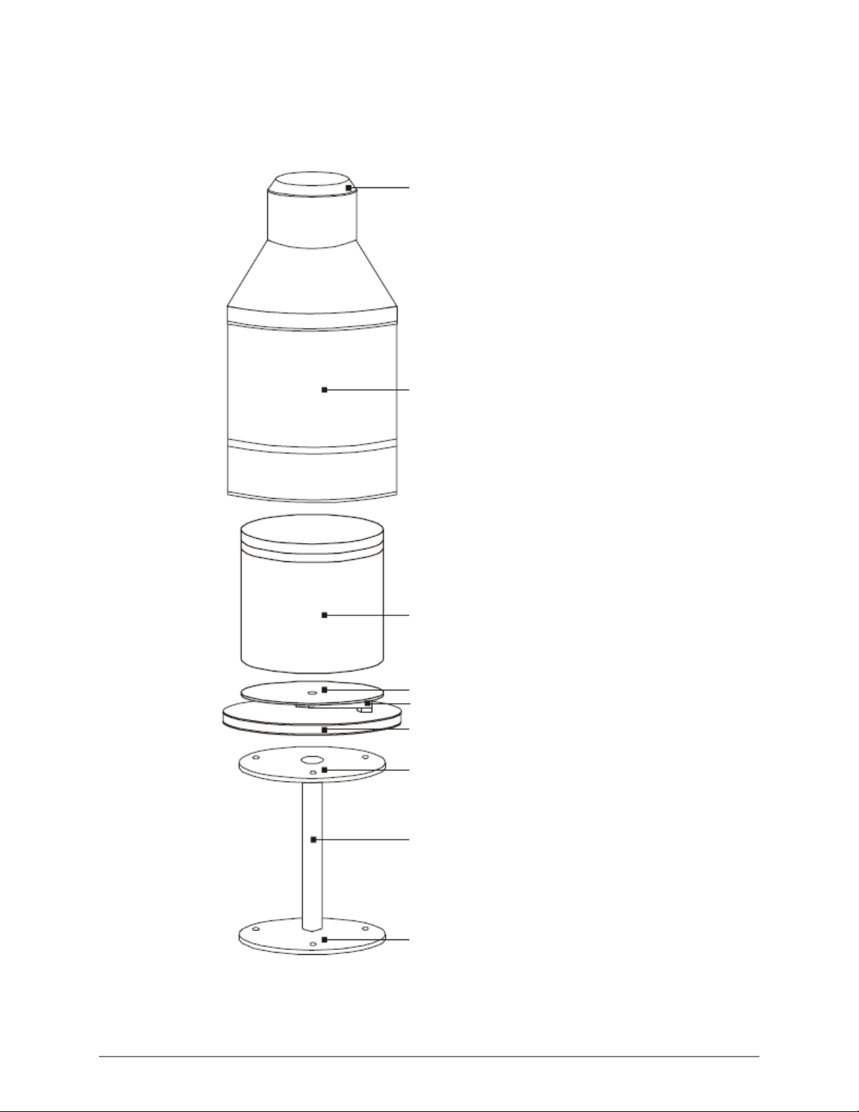
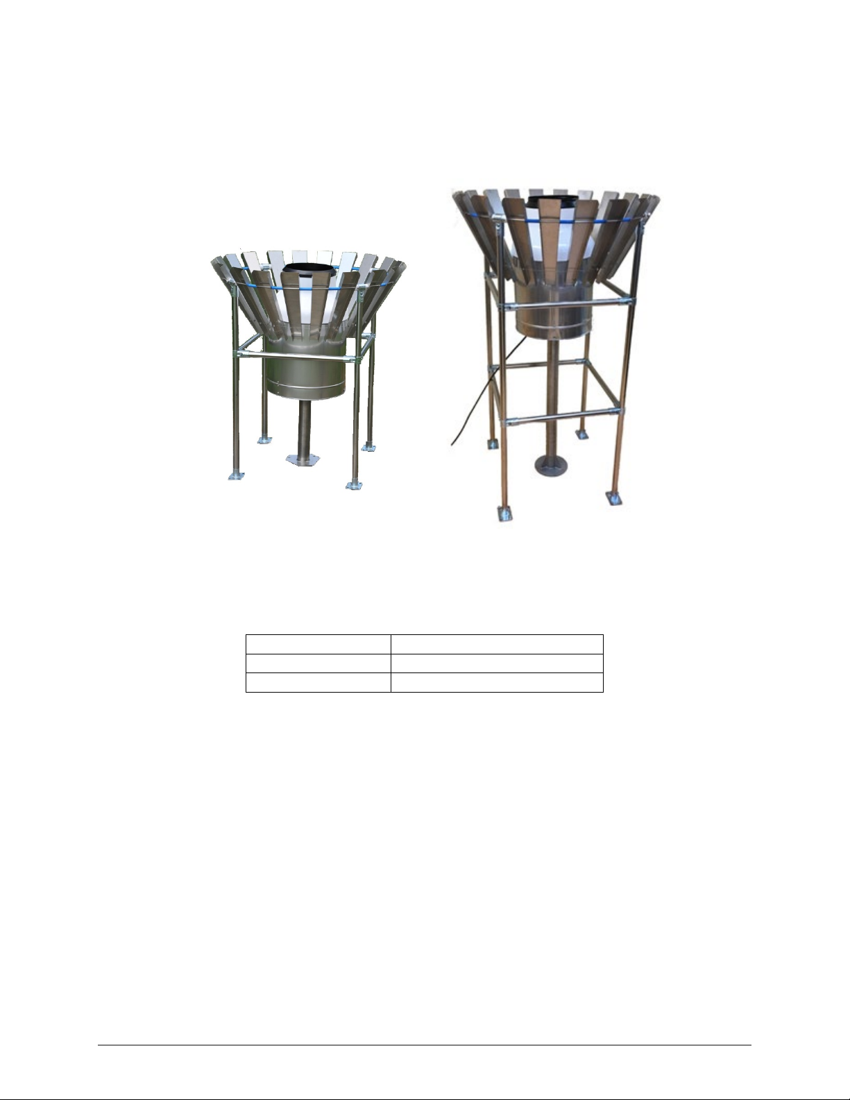
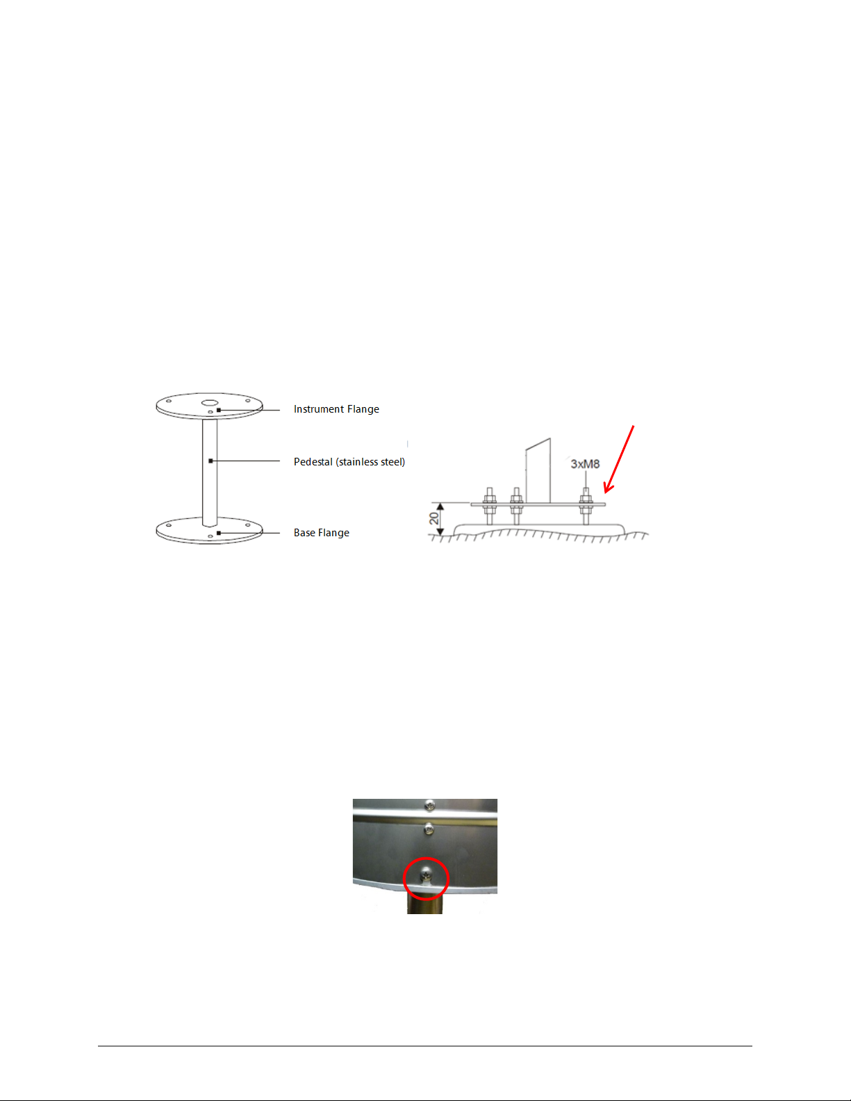
1.2 PARTS......................................................................................................................................................................................2
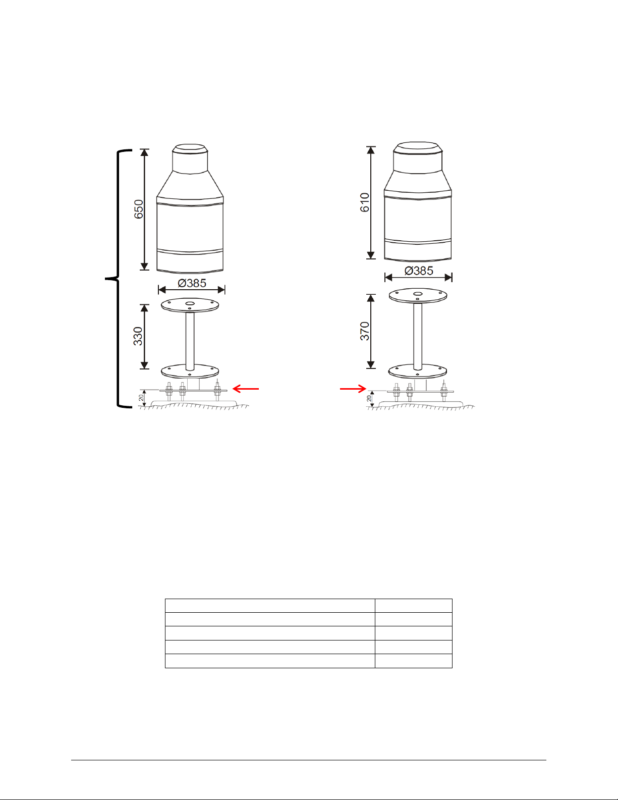
1.3 MOUNTING HEIGHTS ........................................................................................................................................................3
1.4 WIND SHIELD .......................................................................................................................................................................4
2.1 SITE SELECTION...................................................................................................................................................................5
2.2 CONCRETE BASE .................................................................................................................................................................5
2.3 REQUIRED TOOLS...............................................................................................................................................................6
2.4 MOUNTING ...........................................................................................................................................................................6
2.5 CALIBRATION VERIFICATION..........................................................................................................................................9
2.6 MAINTENANCE..................................................................................................................................................................11
2.6.1 EMPTYING THE BUCKET......................................................................................................................................11
2.6.2 VISUAL INSPECTION .............................................................................................................................................11
2.6.3 ANTIFREEZE .............................................................................................................................................................12
2.7 TRANSPORTING THE AWP.............................................................................................................................................12
3.1 NOTATION FOR SDI COMMANDS ..............................................................................................................................13
3.1.1 BASIC COMMANDS...............................................................................................................................................13
3.1.2 MEASUREMENT AND SEND DATA COMMANDS .......................................................................................14
3.1.3 CONTINUOUS MEASUREMENT.........................................................................................................................15
3.2 X COMMANDS ...................................................................................................................................................................15
3.2.1 RAIN COUNTER RESET .........................................................................................................................................15
3.2.2 TIME SYNCHRONIZATION COMMAND..........................................................................................................16

Page 1/18
700-AWP-Man Rev 3 18 Jul 2018
GENERAL
1.1 GENERAL
The FTS All Weather Precipitation (AWP) Gauge is an SDI-12 sensor which measures all types of
precipitation within a wide temperature range. It is designed to withstand harsh wind and snow
conditions without sacrificing sensitivity and accuracy. It boasts a combination of simple mechanical
construction and sophisticated firmware, guaranteeing superior performance.
The AWP Gauge is available in two models which come with a mounting template for the installation
of the pedestal and optional wind shield:
SDI-AWP-200 SDI-AWP-400
Orifice area
200 cm2 400 cm2
Capacity
1500 mm 750 mm
The factory default address is 1. If your AWP will be used with a pre-set configuration, ensure it is set
to the address used in the configuration file.
CAUTION! When the bucket is at capacity it weighs 30 kg (66 lbs).
1.1.1 KEY FEATURES:
•Measurements of solid and liquid precipitation with one-minute rain intensity, total sum of
precipitation and rain duration
•Elimination of wind vibration, particles, false weight changes, evaporation and temperature
fluctuation
•Easy to maintain
•Evaluation and accuracy check “in situ”
•Bucket capacity alert function
•Orifice heating optional
•Output: SDI-12
•Wind Shield and Pedestal (in 1m or 1.5m {3.3 ft or 4.9 ft} sizes) are available as well

700-AWP-Man Rev 3 18 Jul 2018 Page 2/18
1.2 PARTS
The following exploded view shows the major components of an AWP.
Figure 1-1: Major components of an AWP
Orifice – collecting ring with heating
Housing (stainless steel or laminate)
Bucket (UV stabilized plastic)
Support plate (aluminum-base alloy)
Strain gauge bridge
Instrument Flange
Base Flange
Pedestal (stainless steel)
Base plate with internally sealed electronics
housing

700-AWP-Man Rev 3 18 Jul 2018 Page 3/18
1.3 MOUNTING HEIGHTS
Each model of AWP is mounted on a pedestal. There are two heights of pedestals for each model of
AWP so that the resultant height of the orifice will be either 1m or 1.5 m. The pedestal sizes are
identified by the resultant height of the AWP orifice not the pedestal height itself.
AWP 200 AWP 400
Figure 1-2: AWP200/AWP400 showing 1m pedestals
Unless otherwise indicated, all measurements are in mm.
Resultant orifice height is determined by:
The distance from the ground to the lower flange of the pedestal (20 mm) +pedestal height + AWP
height.
Table 1-1: Pedestal Part Numbers
ITEM
PART #
AWP - 200 Gauge, 1m (3.3 ft) pedestal
19632
AWP – 200 Gauge, 1.5m (4.9 ft) pedestal
19633
AWP -400 Gauge, 1m (3.3 ft) pedestal
19071
AWP – 400 Gauge, 1.5m (4.9 ft) pedestal
19072
1m
Detail of mounting
base with lower
pedestal flange
attached

700-AWP-Man Rev 3 18 Jul 2018 Page 4/18
1.4 WIND SHIELD
An optional wind shield can be ordered for the AWP.
1m wind shield 1.5m wind shield
Figure 1-3: AWP with Wind Shield
ITEM
Description
AWP-WS-1M
Wind Shield, 1m (3.3 ft)
AWP-WS-1.5M
Wind Shield, 1.5m (4.9 ft)

700-AWP-Man Rev 3 18 Jul 2018 Page 5/18
INSTALLATION AND MAINTENANCE
2.1 SITE SELECTION
•The installation site should be open but protected from winds.
•The distance from the gauge to any obstruction should be at least twice the height of the
obstruction.
•The orifice should be 1 meter above the surrounding terrain
NOTE: If required by local conditions, the orifice may be positioned at a height of 1.5 meters
above the surrounding terrain using the 1.5m pedestal
Figure 2-1: AWP placement
2.2 CONCRETE BASE
The stand should be bolted to a concrete base.
1) Prepare a level concrete base and attach three M8 or 5/16” bolts corresponding to the holes in
the base flange of the mounting stand. Use the MPS TRWS Gauge template provided with
your shipment (drawing #19634) which also includes the template for wind screen mounts.
IMPORTANT! When preparing the concrete base, ensure mounts for the wind screen
(if being used) are also constructed.
2) Screw a nut onto each of the bolts so that the distance above ground level is 20 mm. Refer to
Figure 2-2.

700-AWP-Man Rev 3 18 Jul 2018 Page 6/18
2.3 REQUIRED TOOLS
In order to install the AWP, the following tools are required:
•Philips #2 screwdriver
•M8 or 5/16” open end or combination wrench (in accordance with bolts in concrete base)
•6 x M8 or 5/16” nuts (to match bolts in concrete base)
•3 x washers for mounting the base flange
•One of a 20g, 25g, 50g or 100g weight (for calibration verification of the sensor)
2.4 MOUNTING
1) Place the lower flange of the pedestal onto the nuts
Figure 2-2: Base and mounting the pedestal
2) Confirm the stand is level by placing a bubble level on the instrument flange. Check the
horizontal plane in two directions perpendicular to each other. Adjust the lower nuts as
necessary to achieve a level horizontal plane.
3) Fix the stand using another 3 nuts and washers. Do not fully tighten the nuts.
4) Detach the stainless steel/laminate cover from the rain gauge base plate by loosening the
three bolts at the bottom edge of the housing.
Base flange

700-AWP-Man Rev 3 18 Jul 2018 Page 7/18
5) Remove the packing supports and packing material from the interior of the housing.
6) Lift the bucket from the support plate.
7) Attach the base plate to the stand using the three bolts with a locking washer.
8) Check the horizontal position of the support plate with a level and adjust the position using
the lower flange nuts if necessary. Once level, tighten all nuts thoroughly.
9) The rain gauge’s support plate is fitted with one of two styles of restraints to prevent damage
during transport.
One has two transport screws and a transport detent to prevent damage during transport.
Loosen both screws so that there is a space of at least 1mm between the tip of the screw and
the body of the gauge and remove the transport detent.Retain the transport detent as it
should be used any time the instrument is transported. See Figure 2-3.
Figure 2-3: Transport restraints - detent
TRANSPORT
DETENT
Remove packing
material
TRANSPORT
DETENT

700-AWP-Man Rev 3 18 Jul 2018 Page 8/18
The other uses three transport bolts and with ½” nuts. Unscrew each nut enough to expose
the top of the bolt.
Figure 2-4: Transport restraints - bolts
10) Replace the bucket ensuring it is correctly centred.
11) Replace the housing, aligning the male part of the heat connector with the female connector
located on the base plate and the outer slots with the bolt holes on the base. Press down
firmly until there is no gap between the outer lip of the housing and the base ridge. Secure
the housing with the bolts.
12) In order for the AWP to function correctly, there can be no contact between the bucket and
the housing.
HINT: Run your finger between the bucket and the housing to ensure there is no
contact between the two.
13) Connect the SDI-12 cable to one of the SDI ports on an Axiom data logger using the military
connector.
14) Wait 4 minutes and check the weight reported by the gauge. A weight of approximately
1530g (the weight of the empty bucket) should be returned.
15) If the expected weight is not returned, review the setup and repeat #14. If the expected
weight is still not returned, do a calibration verification.
16) If operating in an area in which freezing conditions are expected, add 500 ml of
environmentally friendly antifreeze to the bucket. See section 2.6.3 for details of using
antifreeze.
IMPORTANT! DO NOT add antifreeze directly to the bucket when it is on the support
plate as that will be measured as precipitation.See section 2.6.3.
Nuts positioned for transport
Nuts positioned for use
Support plate

700-AWP-Man Rev 3 18 Jul 2018 Page 9/18
2.5 CALIBRATION VERIFICATION
Once the AWP is in place, powered, and configured with the Datalogger, you can conduct an optional
calibration verification to ensure its operation and accurate conversion of weight to amount of
precipitation.
1) Remove the housing and bucket. Empty the bucket and ensure it is dry and clean.
2) Replace the bucket and housing. Wait four minutes for the AWP to stabilize.
IMPORTANT! The housing MUST be in place on the base prior to proceeding.
3) Confirm the weight reading is approximately 1530g.
4) Carefully place the weight in the bottom of the bucket. The housing can be removed in order to
conduct this step, but it must be replaced prior to proceeding.
5) From the transparent mode, send the clear cumulative precipitation command (aXclrCV!)1
6) Wait four minutes for the cumulative precipitation calculations to complete.
7) Enter the continuous measurement command (aR!)1
8) The reply will consist of the following:
a{Pr1m}{Wavg1}{PrTotal}
In which:
a= sensor address
Pr1m = one minute sum of precipitation (mm) (range 0 – 120.000)
Wavg1 = total weight (g) (range ±40000.00)
PrTotal = overall sum of precipitation (mm) (range 0 –999.999
Example Response for an AWP-200 using a 100g weight: 1+0+100.01+4.987
9) If the first value after the sensor address (Pr1m) is not zero, wait another minute and resend the
continuous measurement command (further stabilization and averaging are required).
10) Compare the PrTotal to the reference table to ensure the returned value corresponds to the limits
set out therein
1In which a is the sensor address

700-AWP-Man Rev 3 18 Jul 2018 Page 10/18
TABLE 2-1: REFERENCE TABLE FOR VERIFICATION PROCEDURE. RELATIVE ACCURACY 1%
Weight
(g)
AWP-200
AWP-400
Min
Nom.
Max
Min
Nom
Max
20
0.990
1.000
1. 01
0.495
0.500
0.505
25
1.238
1.250
1.263
0.619
0.625
0.631
50
2.475
1.500
02.525
1.238
1.250
1.263
100
4.950
5.000
5. 050
2.475
2.500
2.525
In the example response in (8), we see the PrTotal of 4.987 for an AWP-200 using a 100g weight
falls within the verification range.
11) Remove the housing, bucket and weight to reset the gauge.
12) If using antifreeze, add it to the bucket before replacing the bucket on the support plate. Replace
the bucket and housing and secure.

700-AWP-Man Rev 3 18 Jul 2018 Page 11/18
2.6 MAINTENANCE
The AWP requires minimal maintenance. Refer to the following table for the recommended
maintenance routine:
Table 2-2: Recommended maintenance schedule
Empty bucket
At every site visit or when bucket nears 80% of its full capacity
Visual Inspection
Annually (minimum); at every site visit
Add Antifreeze
If operating in freezing conditions
2.6.1 EMPTYING THE BUCKET
The bucket contents can be emptied at any time; however, it is prudent to empty it after long periods
of precipitation or when the bucket is at 80% or more capacity. Should the bucket overflow,
measurements will be inaccurate but the weighing mechanism and other electronics will not be
damaged.
The contents of the bucket can be emptied by siphoning, pumping, or pouring. The first two are the
preferred method if the bucket is at near capacity or if it has a wind shield. If pouring, there is a risk of
injury if proper workplace techniques are not used.
CAUTION! When the bucket is at capacity it weighs
30 kg (66 lbs).
•Consider reducing the load by removing some contents by bailing, siphoning, or pumping.
•If necessary, solicit assistance
•Use proper lifting techniques
•Minimize twisting
To pour out the contents of the bucket, remove the cover as described in step 4 of section 2.4.
Carefully lift the bucket from the base plate and pour out the contents. Inspect the interior for any
debris and remove.
Replace the bucket, cover and screws. Ensure the bucket is properly seated by running your finger
between the bucket and the cover to ensure there is no contact between the two.
2.6.2 VISUAL INSPECTION
When at the site, inspect for any signs of visible damage to the components including cable runs.
Check all the fittings to ensure they are still tight.
Remove any dirt and debris which may have accumulated around the instrument and in the bucket.
Ensure the bucket is properly seated by running your finger between the bucket and the cover to
ensure there is no contact between the two.

700-AWP-Man Rev 3 18 Jul 2018 Page 12/18
2.6.3 ANTIFREEZE
The collection bucket is very sturdy and will maintain its shape even if its contents freeze. If the AWP
will be operating in temperatures below freezing, it is recommended to add 500 ml of
environmentally friendly antifreeze to the bucket to prevent the collected precipitation from
solidifying.
Selecting Antifreeze
When selecting an antifreeze product consideration should be given to the following:
•Propylene glycol based (or other environmentally friendly formulation)
•Water soluble
•Low evaporation point
•Compatible with AWP construction materials
IMPORTANT! Follow manufacturer’s directions for the safe handling, storage and
disposal of the antifreeze being used.
Adding Antifreeze
The bucket should be removed from the support plate and its contents emptied before adding anti-
freeze. Add the anti-freeze and then replace the bucket and housing.
NOTE: DO NOT pour antifreeze directly into the bucket when it is sitting on the base
plate as the AWP will register that as precipitation.
Disposal
When disposing of bucket contents treated with antifreeze, ensure all local regulations are observed
and due consideration given to environmental protection.
2.7 TRANSPORTING THE AWP
When transporting the AWP, it should be prepared to prevent movement of the interior elements.
Restrain the support plate using the supplied transport detent/ transport nuts. Refer to Section 2.4
Step 9. Consider using a removable thread locker designed to lock the nuts against vibration
loosening.
Use firm packing material in the narrow portion of the housing to hold the rain bucket in position on
the support plate. See picture in section 2.4 Step 5.

700-AWP-Man Rev 3 18 Jul 2018 Page 13/18
SDI-12 COMMANDS
3.1 NOTATION FOR SDI COMMANDS2
SDI commands are strings of characters sent to the SDI device. The format of the strings is important,
and to specify the format of SDI commands different typefaces are used. All commands (and the
replies from the device) are represented in a mono-spaced font. Different parts of a command are
represented with variants on this text format
Item Explanation Font Text representation
Command literal Part of a command that must be
reproduced literally as it appears
Bold X
Command
parameter
Part of a command that must be
filled in with an appropriate value
Italic data
Address part of
command
First character of command
(except Address Query). Valid
values 0-9, a-z, A-Z.
Italic a
Command
Terminator
Mandatory character Bold !
3.1.1 BASIC COMMANDS
Command Name
Command
Code
Response and Explanation
Address Query
?! a
Acknowledge Active
a! a
Change Address
aAb! bis the new address, a single alphanumeric character in the
range 0-9, a-z, A-Z
Send Identification
aI! a13MPSSYSTMTRWS6_vvvxxxxxxxxxxxxx
a = address
13= SDI-12 compatibility number (SDI-12 version 1.3)
MPSSYSTM = manufacturer identifier
TRWS6 = sensor model number
vvv = firmware version number
xxxx…. :xxx = detailed firmware number: serial #
2A detailed description and explanation of SDI-12 commands can be found in, “SDI-12: A Serial-Digital Interface
Standard for Microprocessor-Based Sensors Version 1.3”, published by the SDI-12 Support Group. http://www.sdi-
12.org/archives/SDI-12%20Specification%201.3%20July%2025%202004.pdf

700-AWP-Man Rev 3 18 Jul 2018 Page 14/18
3.1.2 MEASUREMENT AND SEND DATA COMMANDS
Even though the M and D commands are implemented, it is highly recommended to use the R
command (section 3.1.3) to get data from the AWP.
Command Name
Command
Code
Response and Explanation
Start Measurement
aM!
atttn
a= sensor address
ttt = the time in seconds until the sensor will have the
measurement(s) ready
n= A digit between 1 and 9. The number of measurement
values the sensor will make and return in response to a D
commands.
Send Data
aD!a{Pr1m}{Wavg1}{PrTotal}
a= sensor address
Pr1m1= one minute sum of precipitation (mm) (range – 12.)
Wavg1 = total weight (g) (range ±4.)
PrTotal = overall sum of precipitation (mm) (range –999.999
Note 1 - sum of precipitation is accumulated from the time power is supplied to the AWP or the reset counter to
zero command is entered.
EXAMPLE:
Request: 1M! Sensor at address 1 take a measurement
Response: 10003 Address = 1, Measurement time = 0 sec, 3 measurement values
Request: 1D0! Sensor at address 1, send data
Response: 1+0.134+7995.146+21.246
Address = 1
Pr1m = +0.134 mm
Wavg = +7995.146 g
PrTotal = +21.246 mm

700-AWP-Man Rev 3 18 Jul 2018 Page 15/18
3.1.3 CONTINUOUS MEASUREMENT
Because the AWP is able to continuously measure, a start measurement command is not required. The
R command can be used to read directly and return the data. The response is formatted like the D
command.
Command Name
Command
Code
Response and Explanation
Continuous
Measurement
aR0! a{Pr1m}{Wavg1}{PrTotal}
a= sensor address
Pr1m1= one minute sum of precipitation (mm) (range 0 – 120.000)
Wavg1 = total weight (g) (range ±40000.00)
PrTotal = overall sum of precipitation (mm) (range 0 –999.999
Note 1 - sum of precipitation is accumulated from the time power is supplied to the AWP or the reset counter to
zero command is entered.
EXAMPLE:
Request: 1R0! Sensor at address 1, send data
Response: 1+0.134+7995.15+0.246
Address = 1
Pr1m = +0.134 mm
Wavg1 = +7995.15 g
PrTotal = +0.246 mm
3.2 X COMMANDS
3.2.1 RAIN COUNTER RESET
This command resets the state of the rainfall counter RainSum to zero. There is no need to use this
command to reset the counter after each read as the counter will roll over automatically at the
Rainsummax value of 100mm.
Command Name
Command
Code
Response and Explanation
Reset Rain Sum
Counter
aXclrCV!
aN
a= sensor address
N = count of cleared cumulative values

700-AWP-Man Rev 3 18 Jul 2018 Page 16/18
3.2.2 TIME SYNCHRONIZATION COMMAND
This command synchronizes the internal measurements with the data logger’s time. The time base of
the AWP measurement is one minute. Therefore, the minimum interval between time synchronization
commands must be an integer multiple of this base (60 seconds).
Command Name
Command
Code
Response and Explanation
Synchronize Time
aXSYN!a
Note 1 - When the AWP is used with a data logger, it is recommended to synchronise every minute at least 1
second before sending a request for data.

700-AWP-Man Rev 3 18 Jul 2018 Page 17/18
SPECIFICATIONS
AWP 200
AWP 400
MEASUREMENT
Orifice area
200 cm2
400 cm2
Capacity
1500 mm
750 mm
Accuracy
0.1%
Maximum Rain Intensity
120 mm/min
Resolution
0.001mm
Measuring Element
Strain-gauge bridge
Air Temperature Measurement
Optional, -40 to +70 (± 0.5C)
Wind Correction
Yes
Wind Shield
Optional
ELECTRICAL & INTERFACE
Power supply
5 – 30VDC/ 4mA max
Serial output
SDI-12
MECHANICAL
Dimensions
385 x 650 mm
385 x 610 mm
Weight
9.5 kg
ENVIRONMENTAL
Operating Temperature Range
-40 to +70C
Operating Humidity Range
0 – 100%
Degree of Protection
IP65
This manual suits for next models
4
Table of contents
Other FTS Accessories manuals
Popular Accessories manuals by other brands

Liebert
Liebert UPStation S VCR232CR Installation and instruction manual

Norazza
Norazza Data Destroyer DD7000 Features

ETC
ETC Echoflex UWLDU-3 installation guide

Vega
Vega VEGAKON 61 operating instructions

Smith's Heating First
Smith's Heating First Edge Pro Compact owner's manual

Apogee
Apogee SQ-514 owner's manual