FTS DTS-12 User manual

EXTREME ENVIRONMENTS. EXTREMELY RELIABLE.
DTS-12
SDI Turbidity Sensor
User Manual
1.800.548.4264 | www.ftsinc.com
700-DTS-12 Rev. 28 16 Apr 2020

i
Table of Contents
Chapter 1 OPERATION .................................................................................................... 1
1.1 General description ......................................................................................................... 1
1.2 Unpacking ......................................................................................................................... 2
1.3 Site Selection..................................................................................................................... 2
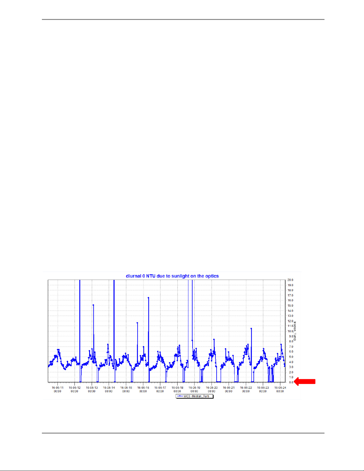
1.3.1 Avoiding Sun Spikes 2
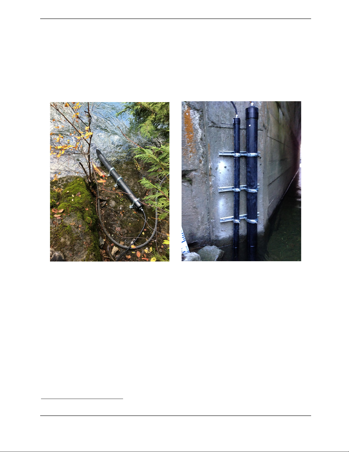
1.4 Installation ........................................................................................................................ 3
1.5 SDI Connection................................................................................................................. 4
1.6 SDI-12 connectorized cable ............................................................................................ 5
1.6.1 Cable Connection and Disconnection (Original model) 5
1.6.2 Cable Connection and Disconnection (V2) 8
1.7 Operation .......................................................................................................................... 9
1.7.1 Turbidity Measurement 9
1.7.2 DTS-12 Calculations 9
1.8 Address Configuration ..................................................................................................10
1.9 Calibration.......................................................................................................................10
1.10 Maintenance ...................................................................................................................10
1.10.1 Routine Cleaning 10
1.10.2 Changing the Wiper Blade 10
1.10.3 Replacing the Wiper Blade Assembly 12
1.11 Replacement Parts.........................................................................................................12
Chapter 2 QUICK START GUIDE ................................................................................... 13
2.1 Detecting the DTS-12.....................................................................................................13
2.2 Mapping the Sensor.......................................................................................................14
2.3 Configuring the DTS-12 .................................................................................................15
2.4 Setting up Logging – In-line Logging Enabled.............................................................16
2.5 Setting Up Logging - Regular Logging..........................................................................17
Chapter 3 SDI-12 COMMANDS..................................................................................... 19
3.1 Notation for SDI-12 Commands...................................................................................19
3.1.1 General SDI-12 Commands 19
3.1.2 SDI-12 Measurement and Request Data Commands 20
3.2 SDI-12 Commands for DTS-12 ver 20 or later............................................................21
3.2.1 Measurement Command Table(ver 20 and later) 22
3.2.2 Request Data Commands 22

ii
3.2.3 Extended (X) Commands 23
3.3 SDI COMMANDS FOR DTS-12 (ver 19 or earlier)........................................................23
3.3.1 SDI-12 Measurement Commands 24
3.3.2 Extended (C) Commands (ver 19 and earlier) 25
Appendix A TECHNICAL SPECIFICATIONS ..................................................................... 26
Appendix B ORDERING AND UPGRADE INFORMATION ............................................. 27
Document Revision History ................................................................................................ 28

700-DTS-12 Rev. 28 -16 Apr 2020 Page 1/28
Chapter 1 OPERATION
1.1 General description
The FTS DTS-12 Turbidity Sensor (DTS-12) measures turbidity and suspended solids concentrations in
liquids. The method used is called optical back scatter and employs a detector at 90 degrees to the
incident light beam. Light is emitted into a liquid medium and any amount of reflection detected from
suspended matter is a measure of the turbidity of the medium. To achieve this result, the latest in
micro power, solid state, and infrared laser technology is used. The laser light output is modulated
and synchronously detected so that any effects from ambient light conditions are minimized. The
measurement range of the DTS-12 is 0 to 1600 NTU, making it ideal for stream and river applications.
The DTS-12 has a built-in wiper that is useful for reducing the effects of silt build up and biological
fouling of the sensor optics. The DTS-12 is factory programmed with turbidity calibration coefficients.
The micro controller applies these coefficients to the raw measurement data and computes mean,
median, maximum, minimum, variance, and BES (Best Easy Systematic estimator). All turbidity data is
returned in NTUs (Nephelometric Turbidity Units).
All control and measurement functions of the DTS-12 are initiated by sending it an SDI-121command.
Figure 1-1: DTS -12
1SDI-12 = Serial Data Interface at 1200 baud. It is a standardized protocol that defines how microprocessor based sensors can
communicate with data loggers

700-DTS-12 Rev. 28 -16 Apr 2020 Page 2/28
1.2 Unpacking
You should have received the following materials with each DTS-12 sensor:
1. DTS-12 Turbidity Sensor complete with 25’ (or user specification) of polyurethane cable.
2. Spare wiper blade.
3. DTS-12 SDI Turbidity Sensor Operating Manual
1.3 Site Selection
The sensor should be located in an area that is representative of the water to be measured,
preferably in a shaded area.
1.3.1 Avoiding Sun Spikes
It is possible for direct or reflected sunlight to affect the DTS-12 measurements. Selecting a shaded
site will eliminate the possibility of sunlight affecting the DTS-12 turbidity readings; however, if a
shaded site is not available, if possible, mount a shade to eliminate sunlight effects on the DTS-12.
The installation directions (Section 1.4) contain further details on how to optimally deploy the DTS-12
to avoid interference from sunlight.
A typical data set from the DTS-12 from a sunlight affected deployment is shown below. Note the
daily pattern of zeroes in the turbidity measurement. In older DTS-12 units, sunlight affected
readings will be large positive spikes. The difference in how the older and newer units respond to
sunlight is due to how the DTS-12 firmware handles the erroneous readings.
Figure 1-2: DTS-12 data showing 0 NTU

700-DTS-12 Rev. 28 -16 Apr 2020 Page 3/28
1.4 Installation
In most cases the best deployment for a turbidity sensor is inside a 4“ inner diameter protective pipe
(typically schedule 40 Aluminum or PVC pipe) that is placed in the river and fastened securely to the
shore by various means (concrete pillars, metal stakes etc.) as shown in the examples in Figure 1-3.
Figure 1-3: Example Installations
When deploying the DTS-12 sensor NEVER use the DTS-12 cable to position or remove the sensor.
Ensure its optic face is pointed away from direct sunlight. Generally, it is best to point the sensor face
downward. The exception to this is when deploying the sensor into shallow water where the bottom
or sides of the stream bed are highly reflective. For these applications, be sure to mount the sensor
so that the optic face avoids not only direct sunlight but reflected sunlight as well.
The DTS-12 must be oriented such that the optical window has at least 4 inches axial end clearance
and 2 inches radial side clearance from any physical objects (e.g. the river bottom or protective pipe).
The sensor should be located in an area that is representative of the water to be measured.
See Figure 1-4. If in doubt as to the how to deploy your DTS-12, consult FTS regarding deployment
options for your site. To aid in installation, FTS can supply a DTS-12 sensor deployment guide2.
2Part Number DTS-12-DG (Turbidity Sensor Deployment Guide Assembly)

700-DTS-12 Rev. 28 -16 Apr 2020 Page 4/28
Figure 1-4: Typical DTS-12 Installation using FTS DTS-12 Deployment Guide
1.5 SDI Connection
The SDI cable (nominally 25 feet long) may be connected to the DTS-12 by waterproof gland or
underwater connector. Normally the free end of the cable is shipped with a length of the
polyurethane jacket removed to expose the three 20 AWG conductors. This allows maximum
flexibility when connecting to a data logger that uses a terminal strip.
The SDI cable may be optionally terminated with a 3-pin military connector for connection to a similar
connector on the Axiom Datalogger. Cable wire colour coding and FTS standard connector pinouts3
are shown in the table and diagram below:
Wire colour Pin Function
Red A +12 V DC power supply
White B Data
Black C Ground
3Waterproof military-style bayonet connector 851-06JC8-3AP50; FTS part number 520-83AP; compatible with FTS
Axiom Dataloggers.
Axial and radial
clearances
FTS DTS-12
Deployment Guide
(two sections)
Protective pipe
Push Rod attached to
deployment guide (to
prevent pulling on
the DTS-12 cable
when positioning or
removing the sensor)

700-DTS-12 Rev. 28 -16 Apr 2020 Page 5/28
1.6 SDI-12 connectorized cable
The DTS-12 can be ordered with fixed length connectorized cables (60 and 100 ft.) that allow for quick
disconnect and re-connection. This watertight connection is submersible and permits sensor
removal from a field installation without removing the cable. In complex installations or on
installations with long cable runs this is a very desirable attribute.
There are two styles of connectorized cables and DTS-12 end caps: the original (with a black sleeve)
and the updated version (V2) with a stainless-steel sleeve which will be replacing the original cables.
Note that cables and DTS-12s are not interchangeable between the original and V2 models.
However, original DTS-12s can be returned to FTS to be fitted with the V2 end caps. Details of parts
numbers and ordering details can be found in Annex B. Note that the process for connecting the
original cable is different than the V2 (refer to sections 1.6.1 and 1.6.2).
Original V2
1.6.1 Cable Connection and Disconnection (Original model)
IMPORTANT: The FTS video “How to Connect and Disconnect the Waterproof Connectorized
Cable” should be viewed prior to attempting to disconnect or connect the cable. It can be
viewed at https://www.youtube.com/watch?v=mGD3ECbYVpw&feature=player_embedded
CAUTION: The female receptacles inside the cable connection are susceptible to
damage if the connection is bent or twisted. These actions can splay the female
connections to the point that electrical contact with the male prongs becomes
intermittent.
When working with the cable be aware that it is a tight fit and requires extremely firm handling
without twisting or bending the cable or the connector.
A thin film of dielectric grease is placed on the End Cap Flange during connection at the factory. This
facilitates the operation of the connection and should be reapplied as needed to ensure the

700-DTS-12 Rev. 28 -16 Apr 2020 Page 6/28
connection can be unplugged. If applying dielectric grease, ensure that it is kept out of contact with
the electrical prongs and receptacles to avoid a poor electrical connection.
One of the male prongs on the DTS-12 end cap has a larger diameter than the other two. This larger
diameter prong must be aligned with the two reference nipples on the cable connector (as shown in
the connection photos) to ensure that the prongs are inserted into the correct receptacles. Forcing
insertion into the wrong position will permanently damage the connection. Aggressive twisting can
also result in bending and breaking prongs.
DO:
•Use clean dielectric grease to lubricate the
DTS-12 End Cap
•Keep prongs and receptacles free from
grease
•Keep the End Cap Prongs and Cable
Connection Receptacles dry
DO NOT:
•Disconnect the cable under water
•Leave an unconnected cable connection
underwater
•Bend or twist the cable connection during
connection or disconnection
CONNECTION
The following sequence of photos outlines the connection process.
Figure 1-5: Applying dielectric grease and aligning the prongs
NOTE: Ensure dielectric grease does not come in contact with electric prongs and receptacles.
DTS-12 End
Cap Flange
Cable
Connection
Dielectric
Grease
Dielectric Grease
on End Cap Flange
Large prong aligned
with reference nipples

700-DTS-12 Rev. 28 -16 Apr 2020 Page 7/28
Figure 1-6: Making the Connection
Figure 1-7: Completing the Connection
DISCONNECTION
After unscrewing the locking sleeve, slide it up the cable out of the way. Firmly grip the probe and
cable connection as shown in Figure 1-8 and pull the connection apart. This step can be difficult as
the watertight seal, consisting of a raised collar in the End Cap, must be released from its mating
groove on the Cable Connector.
Figure 1-8: Disconnecting the cable
WARNING:
DO NOT twist and bend the connection
when connecting or disconnecting the cable.
This inappropriate handling WILL damage the
female receptacles inside the Cable
Connection.
For proper technique, see the FTS video at
https://www.youtube.com/watch?v=mG
D3ECbYVpw&feature=player embedded
Firmly push cable connector onto End Cap.
DO NOT bend or twist connection.
Note hand position when pushing
Cable Connector.
Tighten the locking sleeve to
complete the connection.

700-DTS-12 Rev. 28 -16 Apr 2020 Page 8/28
1.6.2 Cable Connection and Disconnection (V2)
When connecting/disconnecting the V2 cable, care must be taken not to damage the DTS-12’s pins.
Always pull/push the cable straight on/off and avoid bending and twisting the cable during
connection and disconnection.
The DTS-12 will be shipped with a protective cap and the
pins will be coated with di-electric grease.
1) Unscrew the orange sleeve and slide it off.
2) Pull the protective cap off to expose the DTS-12 pins.
Note the silver alignment pin which is smaller.
3) Spread di-electric grease on the pins (if necessary)
ensuring none gets on the threads of the end-cap.
NOTE: The pins will be coated with di-electric
grease for shipping but if conducting a maintenance
visit or swapping sensors, additional grease may be
required for established sites.
4) Using the alignment pin as a guide, align the cable
with the DTS-12 pins and push on. Ensure the cap is
firmly seated
5) Slide the stainless-steel sleeve onto the cap and firmly tighten.

700-DTS-12 Rev. 28 -16 Apr 2020 Page 9/28
1.7 Operation
When power is first applied to the DTS-12 a wipe cycle will occur. This is a normal part of the sensor
initialization. When the wiper returns to its normal parked position the DTS-12 is ready to accept SDI
commands.
1.7.1 Turbidity Measurement
A measurement is initiated when the data logger sends an appropriate SDI command to the DTS-12.
When this happens, the DTS-12 will execute a measurement cycle consisting of the following steps:
1. Powering up the sensor head;
2. Calibrating the analog to digital converter circuitry;
3. Reading the water temperature;
4. Wiping (if the command calls for a wipe) if the water temperature is not too low;
5. Acquiring 100 samples at 20 samples per second; and
6. Performing statistical calculations as required.
After about 10 or 20 seconds (this time is dependent on the type of measurement requested) the
sensor will respond with a service request and the data logger will retrieve the measurement by
issuing a SDI “D0” command. The wiper may be activated explicitly as a single operation or implicitly
as the first part of a measurement command. See the section on SDI commands for the individual
command descriptions.
Note: A wipe operation will add an additional 5 seconds to the measurement operation.
1.7.2 DTS-12 Calculations
The statistical calculations performed by the DTS-12 on the 100 samples are shown below:
mean(average) =sum of all measurements/100 =
=1
100
variance = 1
99 ()
median = +
2
BES = + + +
4
minimum =minimum of all 100 readings = min
=
maximum =maximum of all readings = max
=
Where is measurement ‘I’ in the sorted list

700-DTS-12 Rev. 28 -16 Apr 2020 Page 10/28
1.8 Address Configuration
The DTS-12 is shipped with default address 0 (unless shipped as part of an integrated FTS system).
1.9 Calibration
The DTS-12 should be returned to FTS for calibration on an annual basis.
1.10 Maintenance
The only field maintenance required by the DTS-12 is a periodic check of the wiper for deterioration
or fouling with biological or other material. When proceeding to the field, the following items should
be carried in order to conduct routine maintenance:
FOR ROUTINE CLEANING
FOR CHANGING WIPER BLADE
•
Soft, lint-free cloth or wipes
•Methyl or ethyl alcohol, or mild
soap/detergent
•Soft toothbrush
•Replacement wiper blade
4
•Pliers
•Isopropyl alcohol
•Clean toothbrush (ie: different toothbrush
than the one used to clean the DTS-12)
•Loctite 242
•Activator 7649 (to reduce cure time prior to
returning DTS-12 to the water)
1.10.1 Routine Cleaning
If fouling is detected and the wiper blade is in otherwise good condition it may be cleaned and re-
used. Use a soft lint free cloth or wipe with Methyl or Ethyl alcohol, soaps or detergents to clean the
wiper, optic surface and body of the probe. You may also use a soft toothbrush to help remove the
material. Care must be taken not to scratch the optic face as this may affect the sensor calibration.
DO NOT use harsh or abrasive cleansers or petroleum products.
1.10.2 Changing the Wiper Blade
If the wiper blade edge appears ragged or uneven then it should be replaced. Ensure you are
working in a clean, dry area.
4Each DTS-12 is shipped with a spare piece of wiper material packaged in a small zip-lock bag attached to the
cable. If additional replacement parts are needed, refer to Section 1.10

700-DTS-12 Rev. 28 -16 Apr 2020 Page 11/28
IMPORTANT! Do not change the wiper blade in the field without using Activator 7649.
The cure time for Loctite 242 without Activator 7649 is 24 hours. Replacing the wiper
blade without using Loctite or allowing sufficient cure time can result in the wiper
blade loosening and losing contact with the optic face, or even detaching in .
Figure 1-9: Loctite 242 cure time with Activator 7649
1. Remove the wiper assembly consisting of the wiper arm and wiper blade by undoing the
wiper arm thumbscrew with your fingers or pliers. To reduce unnecessary stress on the
wiper drive system hold the wiper arm while turning the thumbscrew counter clockwise.
Wiper arm in “parked” position
Figure 1-10: Wiper Arm Assembly
2. The wiper armature incorporates a slot with a circular opening at the distal end that allows
the wiper material to be maneuvered out of, or into the slot. Slide the old blade off the wiper
arm by sliding it towards the distal end and pulling it through the slot. Pliers may be needed
to achieve this. Feed the new wiper blade onto the wiper arm through the distal slot.
Figure 1-11: Replacing the wiper blade
3. Clean the thumbscrew threads of residual Loctite using the isopropyl alcohol and toothbrush.
M3 x 8
Thumbscrew
Nylon Washer
Wiper Armature
Wiper Blade
Disassembled wiper assembly

700-DTS-12 Rev. 28 -16 Apr 2020 Page 12/28
NOTE: If alcohol and brush are not available, clean the threads as much as possible
by hand.
4. Place the nylon washer onto the thumbscrew and apply Loctite 242 and Activator 7649 in
accordance with the manufacturer’s directions to the threads of the thumbscrew.
5. Re-assemble following the previous steps in reverse order. The wiper armature and blade
should be in the “parked” position just off the optic lens. Refer to Figure 1-11.
6. Wait the recommended cure time (30-60 minutes for Loctite with Activator 7649; 24 hours for
Loctite only) before returning the DTS-12 to the water.
1.10.3 Replacing the Wiper Blade Assembly
Complete replacement wiper arm assemblies may also be purchased from FTS. The complete
assembly can be changed by loosening the thumbscrew to remove the old wiper assembly and
replacing it with the new wiper assembly.
1.11 Replacement Parts
If replacement parts are required, the entire wiper can be ordered from FTS by specifying part
number DTS12-WIPER. If individual components are required, specify the part number according to
the table below.
FTS Part Number Description
DTS12-WIPER Wiper and Armature assembly
993-WIPER-ARM Wiper Armature
698-DTS12-WIPER Wiper Blade
610-M3X8-TMB M3 x 8 Thumbscrew

700-DTS-12 Rev. 28 -16 Apr 2020 Page 13/28
Chapter 2 QUICK START GUIDE
This chapter will take you through the steps to set up the DTS-12 to an Axiom Datalogger. It is meant
as a quick reference. Detailed instructions can be found in the Axiom Operator’s Manual.
Connect the DTS-12 sensor cable to the Datalogger on one of the orange SDI ports. In order for the
sensor to start providing data to the Datalogger it must be:
1. Detected;
2. Mapped;
3. Configured; and
4. Assigned logging.
2.1 Detecting the DTS-12
1) Select the SDI 12 icon. The Datalogger will look for sensors and display the SDI Sensor
Mapping screen. To detect the DTS 12, select the detect icon (magnifying glass)
Figure 2-1: Sensor Mapping Screen
2) When Detect is pressed, the SDI Detect dialog box appears. Leave the checkbox blank.
Select OK.
Figure 2-2: Detecting the DTS-12
Leave Blank

700-DTS-12 Rev. 28 -16 Apr 2020 Page 14/28
3) The DTS12 will appear in the Detected column. If it is matched with the defined sensor and
all fields appear beige, it is properly mapped.
Figure 2-3: Mapped Sensor
4) If any of the defined or detected fields remain red, then mapping must be conducted.
2.2 Mapping the Sensor
1) Scroll down the Detected column to view the detected DTS-12 (which will be defined as NEW).
Figure 2-4: DTS-12 defined as NEW
2) Press on the red Vendor/Serial field of the detected sensor. The Sensor Mapping dialogue
box will appear.
Figure 2-5: Mapping the DTS-12 to the defined sensor

700-DTS-12 Rev. 28 -16 Apr 2020 Page 15/28
3) Use the drop down menu to select DTS12. Select OK. The DTS-12 is mapped.
Figure 2-6 DTS-12 Mapped
2.3 Configuring the DTS-12
1) From the Datalogger’s home page, select the Sensors icon.
Figure 2-7: Home page
2) The next screen will display the icons of the sensors which have been defined. Note that if
the Datalogger has already been configured for the DTS-12 (by loading a Configuration file, or
replacing a DTS-12 for example) the SDI DTS-12 icon will be displayed
Figure 2-8: Sensor page showing defined sensors

700-DTS-12 Rev. 28 -16 Apr 2020 Page 16/28
3) If the SDI DTS-12 icon does not appear, it must be added. To add the DTS-12, select the Add
icon, then press on the SDI Generic icon.
Figure 2-9: Adding the DTS-12
4) The DTS-12 Setup screen will be displayed. Select Edit then press on the blue M2 bar (M
Command).
Figure 2-10: Rain Sensor Setup Screen
5) Input the desired Interval and Offset times. If there is a Configuration File loaded, these will
be automatically populated. Ensure they are correct. Select OK.
i. If In-line Logging has been enabled (from Station<Advanced<Edit<In-line Logging) the
In Line Logging screen will be displayed. Note that if working from a Configuration
file, Logging Intervals have probably already been established.
ii. If In-line Logging is not enabled, you will be returned to the SDI Sensor Setup screen.
2.4 Setting up Logging – In-line Logging Enabled
In order to view and collect data on a variable, it must be logged. In-line Logging provides the user an
option to set up simplified Logging and add variables to Current Conditions from the Sensor Setup
screen . However, In-line Logging does not have the full functionality of regular logging using the
functions in the Data screens. Logging of the variables will be in accordance with the sensor read
Other manuals for DTS-12
1
Table of contents
Other FTS Accessories manuals
Popular Accessories manuals by other brands

Pilz
Pilz PSEN op4B/1 Series operating manual

SICK
SICK WTF26 operating instructions

Applied Physics Systems
Applied Physics Systems 1540 user manual

National Instruments
National Instruments UMI-7764 user guide

PC Treasures
PC Treasures PowerNOW! 5600 user guide

Advantech
Advantech TREK-120 Series user manual