FTS 700-RSS-Man User manual

1/4
EXTREME ENVIRONMENTS | EXTREMELY RELIABLE
CANADA 1065 Henry Eng Place | Victoria, BC | V9B 6B2
USA 1124 Fir Avenue, Suite C | Blaine, WA | 98230
FTS Service and Support: support.ftsinc.com | Toll Free: 1-800-548-4264
700-RSS-QS Rev 14 Feb 2019 |Part # 18465
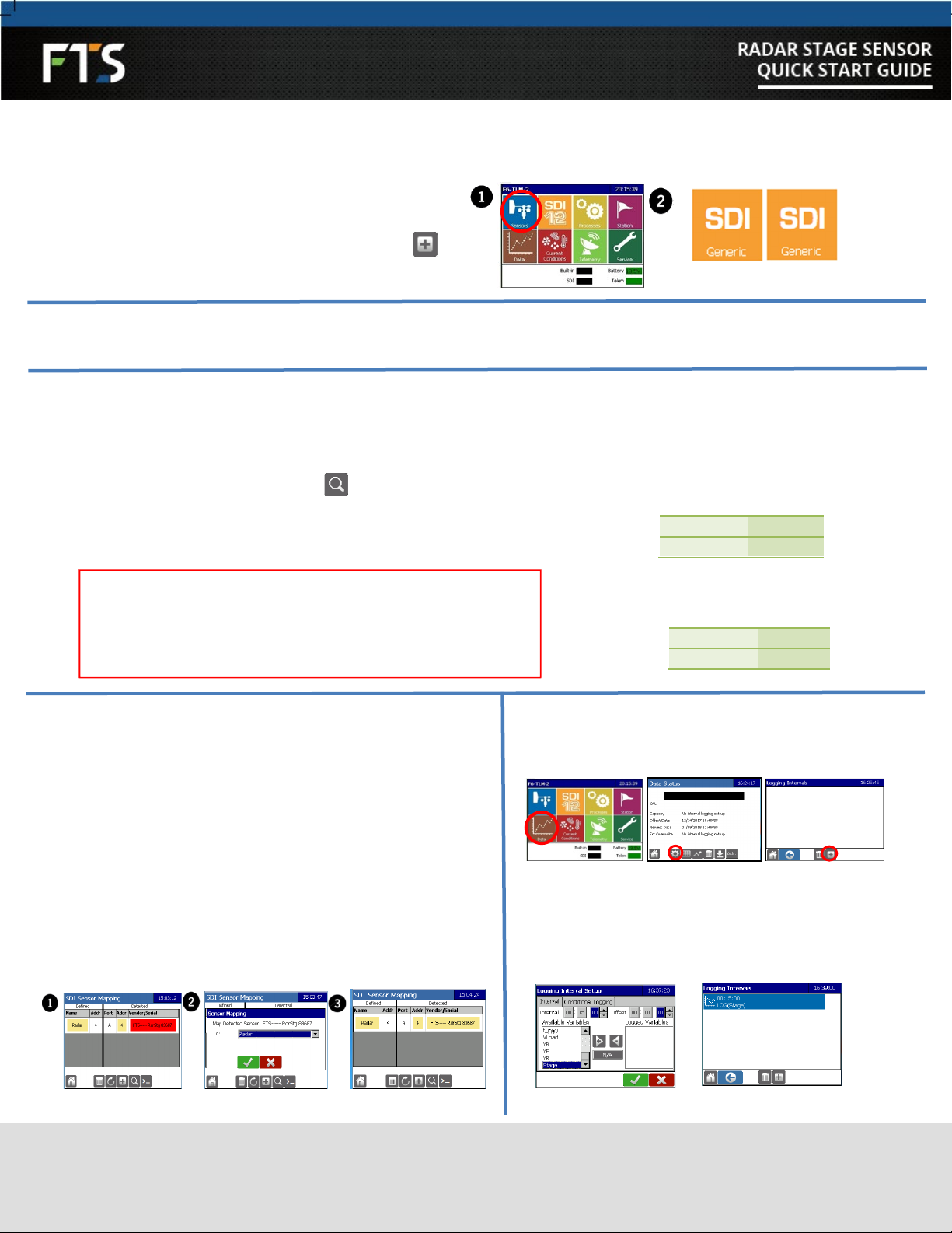
For ease of use the Axiom Datalogger has two sensor extensions which can be used with the Radar.
PACKING LIST
DEFAULT SETTINGS
SECTION 1: Mounting the Radar
SECTION 2: Setting Up with FTS Axiom
Dataloggers
SECTION 3: Setting Up with Other Data Loggers
SECTION 4: Useful SDI-12 Commands
Use the table to determine which
sensor extension to use. If you wish to
measure parameters using more than
one measurement command, you must
use the SDI Generic extension.
1) Keep a minimum horizontal distance of 200mm (7.87”) to
the nearest solid surface and distance to water surface
should not be less than 0.5 m (1.6 ft).
2) Polarization indicators should be turned to the nearest
vertical surfaces to minimize the effects of false echoes.
3) Orient the radar cone perpendicular to the water’s
surface.
Use the supplied bubble level to confirm.
Polarization indicators
The Radar Stage Sensor is shipped
with the following default settings:
SDI-12 Address 0
Units of measurement
Feet
Number of samples to
average
20
Power Mode
High
Radar Stage Sensor with
cable 1
Mounting Bracket
1
Bubble level
1
Quick Start Guide
1
OPTIONAL PARTS:
LCD Display, Military Connector
S *For detailed instructions, refer to the Axiom Operator’s
Manual (700-Axiom-Man) found on the FTS Support site
This Quick Start Guide is meant as a fast reference when setting up your FTS Radar Stage Sensor. For detailed instructions and
explanations, refer to the Radar Stage Sensor Operating Manual (700-RSS-Man) and your data logger’s operating instructions.
M COMMAND
RESULTS
EXTENSION
aM!
Average stage, quality metric.
Averaged over 1-720 samples. Default = 20 samples.
Radar or
SDI Generic
aM1!
Instantaneous stage, distance, quality metric, and internal
temperature (in C)
SDI Generic
aM2!
4-20 mA output current (in mA)
SDI Generic
aM3!
aM4!
aM5!
Supports NOAA distance calculation.
Stage, mean distance, standard deviation, number of
discarded outliers, good sample count and voltage (in
V). Averaged over 1-720 samples.
Sample # Defaults: aM3! = 360 aM4! = 60 aM5! = 15
SDI Generic
QUICK START GUIDE SECTIONS PACKING LIST DEFAULT SETTINGS
1MOUNTING THE RADAR
2SETTING UP WITH AXIOM DATALOGGERS *

2/4
EXTREME ENVIRONMENTS | EXTREMELY RELIABLE
CANADA 1065 Henry Eng Place | Victoria, BC | V9B 6B2
USA 1124 Fir Avenue, Suite C | Blaine, WA | 98230
FTS Service and Support: support.ftsinc.com | Toll Free: 1-800-548-4264
700-RSS-QS Rev 14 Jan 2019 |Part # 18465
IMPORTANT NOTES WHEN USING THE RADAR EXTENSION:
1) Using units of measurement other than feet:
The Radar sensor extension is designed to change the units of measurement through the Datalogger screen. The
Datalogger automatically applies the conversion from the received measurement in feet to the measurement selected on
the sensor extension screen. Changing the sensor’s units of measurement using SDI-12 commands will result in errors as
the Datalogger automatically applies a conversion to the received measurement value which is expected to be in feet.
2) Sensor Mapping:
When the radar sensor is configured using the Radar sensor extension, when mapped, the Datalogger sends SDI-12
commands to revert the sensor to the default settings. If settings other than the defaults are desired, after mapping, any
changes made to the sensor’s slope (units of measurement), sample average, or power mode using SDI-12 commands will
no longer be valid. Map the sensor using the default settings, and once mapped, make the desired changes. Mapping
does not affect settings if the sensor is configured using the SDI Generic extension.
3 Set stage (for Radar extension only)
Once configuration has been confirmed/edited as desired, select the Set Stage button
and enter the stage reading.
PRE-CONFIGURED AXIOM DATALOGGERS – 3 Steps
For efficient set up of the station, it is recommended to use a pre- configured Datalogger or load a Configuration file from a USB stick.
Step 1 Load Configuration File:
1a) Insert the USB stick into one of the USB HOST ports on the Datalogger and select Station> About > Load Configuration.
1b) Connect the radar to
an SDI port on the
Datalogger and select the
SDI12 icon to display the
SDI Sensor Mapping
1c)Press on the red
Vendor/Serial box. Use
the drop down menu to
select sensor type
“Radar” then OK.
Step 2 Confirm Configuration
.
2a) Select Sensors, Radar or SDI
Generic icon (the icon for the
extension which was used to
configure the Datalogger will be
displayed) and then the set up
cog
IMPORTANT! If using the Radar Sensor extension,
use the tab inputs to make any changes to Stage (ie:
units) and Schedule. DO NOT make configuration
changes using transparent mode and SDI-12
commands.
IMPORTANT! Input the current stage reading in the configured measurement units.
2b) Select the Sensor, Stage and Schedule
tabs to review settings.

3/4
EXTREME ENVIRONMENTS | EXTREMELY RELIABLE
CANADA 1065 Henry Eng Place | Victoria, BC | V9B 6B2
USA 1124 Fir Avenue, Suite C | Blaine, WA | 98230
FTS Service and Support: support.ftsinc.com | Toll Free: 1-800-548-4264
700-RSS-QS Rev 11 4 Feb 2019 |Part # 18465
UNCONFIGURED AXIOM DATA LOGGERS - 5 Steps
Step 1 Add Sensor Extension
1a) Connect the radar to one of the Datalogger’s SDI ports
1b) Select the blue Sensors icon and then the Add icon :
1c) Select the desired sensor extension (Radar or SDI Generic)
IMPORTANT! STAGE: The radar’s default units are feet. If units
other than feet are desired, the stage units MUST be set to match
the input units using SDI-12 commands. Go into transparent mode
(Step A #3). Refer to section 3A for SDI-12 commands
Step 4 Map Sensor
From the Home page, select the SDI 12 icon to display the
SDI Sensor Mapping screen.
Step 5 Set up Logging
2) Tap on the red field and use the drop down menu to map
the sensor: Select Radar if using the Radar Extension and
SDI if using the SDI extension.
3) Select OK and the SDI Sensor Mapping screen will indicate
the sensor is mapped.
2) Select the Edit pencil, input the desired Logging
interval and offset. Move all the desired variables to
the Logged Variables column and then press OK.
Repeat as required for additional logging.
Set Stage Example (SDI-12 address 9,
stage height 8.4):
Command
9XSH8.4!
Response
9
3a) Enter Transparent Mode (Select SDI > . Set current stage using the
aXSHn!Command in which the a is replaced with the SDI-12 address of the radar
and n is replaced with the stage height.
Set Stage Units Example (SDI-address 0):
To change stage units to metres
Command
0XSUM!
Response
0
Step 2 Configure
2a) Review the tabs and input desired parameters. Once done, select the OK checkmark.
Step 3 Set Stage
If using the Radar Sensor Extension, refer to Step 3 (above) in Pre-configured Dataloggers. If using the Stage Sensor
Extension, follow these steps:

4/4
EXTREME ENVIRONMENTS | EXTREMELY RELIABLE
CANADA 1065 Henry Eng Place | Victoria, BC | V9B 6B2
USA 1124 Fir Avenue, Suite C | Blaine, WA | 98230
FTS Service and Support: support.ftsinc.com | Toll Free: 1-800-548-4264
700-RSS-QS Rev 14 Feb 2019 |Part # 18465
1) Connect the Radar to the data logger using the
wiring guide.
2) Confirm communication with the sensor, by entering the Send
Identification command: aI! in which a is replaced with the SDI-12
address of the sensor (the example uses address 0, the default
address of the radar)
Command 0I!
Response
0I!013FTS-----RdrStg10198765
3A. SET RADAR PARAMETERS
PIN WIRE DESCRIPTION
GND
Black
Ground
12VDC
Red
10.6 to 16 VDC Input
DATA
White
SDI-12 Data
Bare
Shield Ground
SET STAGE UNITS:
The default stage units are feet. To change use:
aXSUcc!in which the ais replaced with the SDI-12 address of
the radar and cc is replaced with the abbreviated form of stage
units:
STAGE
UNITS ABBREV SLOPE VALUE
Feet
FT
1.0
Inches
IN
12.0
Metres
M
0.3048
Centimetres
CM
30.48
Millimetres
MM
304.8
Custom
CU
As Input by user
Example (radar at SDI-address 0):
To change stage units to metres
Command
0XSUM!
Response
0
Adjusting stage units
will automatically
change the slope
TAKE MEASUREMENT: aM!
GET MEASUREMENT: aD0!
in which the ais replaced with the SDI-12 address of the
radar. Use the desired measurement (M, M1, M2, or M3).
Example (radar at SDI-address 3):
Command
3M!
Command
3D0!
Response
30022
Response
3+3.899+1.000000
SET CURRENT STAGE:
aXSHn!
in which the a is replaced with the SDI-12 address of the radar
and nis the stage reading.
Example (radar at SDI-address 3, stage reading = 12.4):
Command
3XSH12.4!
Response
3
IMPORTANT! Input the current stage reading in the same measurement
units which were previously set. Default units are feet. If unsure which units
of measurement are set, use the Get Stage Unit command (see Section 4)
In addition to the standard set of SDI-12 commands, the FTS Radar Range Sensor has custom SDI-12 commands (X commands) that
access specific features of the sensor. Refer to the Radar Stage Sensor Operating Manual (700-RSS-Man) for a full list and
explanation of the commands. In all commands, the a must be replaced with the SDI-12 address of the radar.
?! Address query Response will be SDI-12
address
aAb! Change address b=the address to change to
aXPMc!
aXPM!
Set power mode
Get power mode c= H or L (H = high, L = low
aXSU! Get stage units
Refer to Stage Units table in
Section 3A
aXAOn!
aXAO!
Set analog offset
Get analog offset n = desired output offset
Range of offset = 0.0 to 20.0
aXASn!
aXAS!
Set analog scale
Get analog scale
n=4-20 mA output scaling
value
3SETTING UP WITH NON-AXIOM DATALOGGERS
4USEFUL SDI-12 COMMANDS
Other FTS Accessories manuals