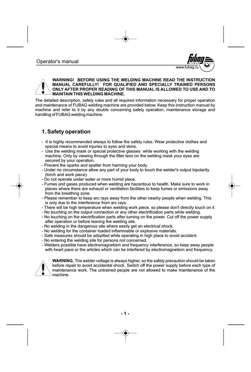
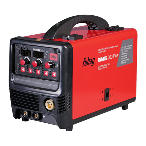
Fubag TS-MIG 250T Pro User manual


Omperator's anual
WARNING! BEFORE USING THE WELDING MACHINE READ THE INSTRUCTION
MANUAL CAREFULLY! FOR QUALIFIED AND SPECIALLY TRAINED PERSONS
ONLY AFTER PROPER READING OF THIS MANUAL IS ALLOWED TO USE AND TO
MAINTAIN THIS WELDING MACHINE.
The detailed description, safety rules and all required information necessary for proper operation
and maintenance of FUBAG welding machine are provided below. Keep this instruction manual by
machine and refer to it by any doubts concerning safety operation, maintenance storage and
handling of FUBAG welding machine.
1. Safety perationo
-
-
-
-
-
-
-
-
-
-
-
-
-
-
-
It is highly recommended always to follow the safety rules. Wear protective clothes and
special means to avoid injuries to eyes and skins.
Use the welding mask or special protective glasses while working with the welding
machine. Only by viewing through the filter lens on the welding mask your eyes are
secured by your operation.
Prevent the sparks and spatter from harming your body.
Under no circumstance allow any part of your body to touch the welder's output bipolarity
(torch and work piece).
Do not operate under water or more humid place.
Fumes and gases produced when welding are hazardous to health. Make sure to work in
places where there are exhaust or ventilation facilities to keep fumes or emissions away
from the breathing zone.
Please remember to keep arc rays away from the other nearby people when welding. This
is only due to the interference from arc rays.
There will be high temperature when welding work piece, so please don't directly touch on it
No touching on the output connection or any other electrification parts while welding.
No touching on the electrification parts after turning on the power. Cut off the power supply
after operation or before leaving the welding site.
No welding in the dangerous site where easily get an electrical shock.
No welding for the container loaded inflammable or explosive materials.
Safe measures should be adoptted while operating in high place to avoid accident.
No entering the welding site for persons not concerned.
Welders possible have electromagnetism and frequency interference, so keep away people
with heart pace or the articles which can be interfered by electromagnetism and frequency.
WARNING. The welder voltage is always higher, so the safety precaution should be taken
before repair to avoid accidental shock. Switch off the power supply before each type of
maintenance work. The untrained people are not allowed to make maintenance of the
machine.
www.fubag.ru
- 1 -

-
Check the connection of input and output cables and the earth (ground) connection, etc.
Maintenance should be conducted by the trained personnel.
The newly installed machine or the welder not in use for some time needs to be checked by
multimeter have the right insulation resistance between each winding and the case.
When the welder is used outdoors, it should be kept from rain or long exposure to the sun.
Check is needed from time to time to make sure the welding cable is in good condition if the
welding machine is in frequent use. Check at least once each month if the welder is in
regular use. It is necessary to check when the welder is in mobile use.
If the welder is not in use either for a long time or temporarily, it should be kept dry and have
good ventilation to free it from moisture, erodible or toxic gas.
- The welder must be installed in the place where it can not be exposed to sun and rain. Also it
must be stored in less humid place with the temperature range at -10 +40 .
Dust removal is needed every year. Check the machine's fasteners, moving-iron, current
regulation screws, etc to make sure there are no loose connection problems.
The dust, acid and erodible dirt in the air at the job site can not exceed the amount required
by the norm (excluding the emission from the welder).
The welder must be installed in the place where it can not be exposed to sun and rain. Also it
must be stored in less humid place with the temperature.
There should be 50 cm space about for the welding machine to have good ventilation.
Make sure that there is no metal-like foreign body to enter the welding machine.
Electrode must be taken down from holder when no welding.
No violent vibration in the welder's surrounding area.
Make sure that there is no interference with the surrounding area at the installation site.
The purity of CO can not less than 99.5%, its water contain not over 0,005%. For gas in the
bottle, it should be stopping using when its air pressure less than 1MPa.
Take measures to prevent wind while operating in the strong wind since the welder is gas
shielded. The wind speed is limited below 1 0 m/s, or the wind shield device must be loaded.
Each item listed below must be carefully checked before operation:
Make sure that there is no short circuit connection with welder's both outputs.
Make sure that there is always sound output and input wire connection instead of exposing it
outside.
Regular check needs to be conducted by the qualified personnel after the welding machine has
been installed over a long period or re-operation, which involves as follows:
Check the welding cable to see if it can continue to be used before it is worn out.
Replace the welder's input cable as soon as it is found to be broken or damaged.
Make sure whether there is enough power supply to make the welding machine work properly.
Any power source required to access the welding machine must be installed with some
protective equipments.
Please do not hesitate to contact us for technical assistance whenever you come across the
problems you can not work out or you may deem difficult to fix.
No switching when welding.
-
-
-
-
-
-
C
-
-
-
-
-
-
-
-
-
-
,
-
-
-
-
-
O
2
Safety Check:
Omperator's anual
www.fubag.ru
--2
2. Technical Specification
The manufacturer reserves himself the right to make the manual's content or welder's function
change without any preliminary notification of the users.
3. Description
Th semi-automatic gas shielded welder Th series welder uses CO as
shielded gas and wire as electrode, is an automatic gas shielded arc welder. The main transformer
and control PCB etc. are installed on the right part of machines.
If welding with large current for a long time and exceed the duty cycle, the overload lamp will be on,
the machine will stop working until looking to the stated temperature. When the overload lamp light
you must stop welding and wait about 15 minutes, you can continue.
is welding machine is . is 2
www.fubag.ru
Omperator's anual
--3
TS-MIG 250T PRO TS-MIG 300T PRO
Input power V
Frequency Hz
Rated input current А 14 17,2
Rated input capacitance kVA 9,2 11,5
No-load voltage V 18~35 19~38
Welding current А 40~250 56~300
Rated duty cycle (at 25°С) % 35 35
Wire diameter mm 0,8-1,2 0,8-1,2
Cooling type
Dimension LхWхH cm 80х37,5х63 83х39,5х71
Weight kg 75 91
Моdel
Fan cooled
3х380
50
11
2
3
44
66
1. Welding Indicator Light
2.
3. Work Piece Interface
4.
5. Long/Spot Welding
Selection Switch
6.
7. /
8.
9.
MIG/MAG Torch
and O
Time Welding
Interface
Power
O light verload light
Сurrent Adjusted Knob
Wire Speed Adjusted Knob
Adjusted Knob
Voltage Adjusted Knob
ON/OFF
N
2
3
7
7
55
9
98
89

Environment to Which the Product Is Subject:
Requirement for Main Supply:
- The surrounding temperature range: when welding: + 40 С;
During transport or in storage: -25 +55 С
- Relative humidity: when at 40 С: ≤50%, 20 С: ≤ 90%
- The dust, acid and erodible materials in the air can not exceed the amount required by the norm
(apart from the emissions from the welding process). No violent vibration at the job site.
-Altitude no more than 1,000m.
The wind speed should no more than 1m/s around the operation places
The voltage oscillogram should display actual sine wave, the oscillation of the frequency should
not exceed ±1% of the rated value.
The oscillation of the supplied voltage should not exceed ±10 of the rated value.
The three phase power supply unbalance rate 5 .
+5
-.
-
-
-
О
О
ОО
when at
%
%≤
4. Environment
www.fubag.ru
Omperator's anual
--4
5. Sign & Pictures Illustration
H
0
IP21
Ground
Frequency
Power
Current
Insulation grade
XDuty cycle
1
2
I
I
Rated pen ircuit oltageoc v
Rated nput urrentic
Rated elding urrentwc
1
URated nput oltageiv
2
URated oadl voltage
SIGN NAME
Protection class
Power source
Welder’s tructures

www.fubag.ru
Omperator's anual
- 5 -
6. Connection Power Source
-
-
Connect “Input Power Cable” on the rear board to three phase power net installed breaker.
Reliably connect “Ground Bolt” on the lower part of welder rear board to power net earth line with
cable which sectional area is not less than that of input power. Please notice power net connect
earth is not means connecting zero.
7. Installation
WARNING! The welder must be well grounded before using. No disassembling of earth cable if
welding is not end, otherwise, it will do harm to human body. When several welders or some other
electrical appliances are using a common grounding device, they must be parallel connection,
series connection is forbidden. The welder's ground cable sectional area should not be less than
that of input power cable.
The welder must be loaded in the place where are less dust, no chemical, erodible, inflammable or
explosive gas and like items around the welding site.
The welder should be installed in the place where it can not be exposed to sun and rain. Also it
must be stored in less humid place with the temperature range: -10~40
There should be at least 50 cm space for the welding machine.
Apparatus to exclude wind and smoke should be equipped if the inside aeration is not sound.
-
-
-
-
℃.

www.fubag.ru
Omperator's anual
- 6 -
8. Installation and Connection Wire Feeder System
-
-
-
-
Select suitable wire according to welding technology. The wire diameter must be matched with
drive roll, wire guide pipe liner and contact tip.
Install the wire spool to the wire spool axle, and then fix.
Open the left side board, you can see the wire feeding system.
Open the wire feed compaction equipment, let the terminal of wire through the wire guide tube,
drive roller and import the wire guide tube of welding torch, and close the impaction equipment,
adjust the compaction nut of drive roller.
9.Connection Torch
The torch is composed by torch stand, connecting cable and handle.
Torch stand is the interface of torch and wire feeding device.
Connecting cable: covered by nylon pipe the liner is loaded in the center of coreless cable. The inner
part of liner is the passage for wire feeding. The space between liner and coreless cable is the
passage for shielded gas. Coreless cable is the passage for current.
Set with a sensitive switch on the handle to control the welding current.
1 - Wire spool axle
2 - Compaction equipment
3 - Compaction nut
1
2
3

www.fubag.ru
Omperator's anual
- 7 -
10. Connection Gas System
-
-
-
Gas regulator in the attached accessories is installed and screwed firmly on the bottle to prevent
air leak.
Connect and firmly screw the two core plug of heater cable on the gas regulator to “Heater Socket”
on the rear board of welder.
Connect the one end of gas pipe in the attached accessories with the outlet of gas regulator and
firmly hold with hoop also in the attached accessories, the other end to “Gas Inlet” (gas valve joint)
on the back of wire feeder device.
Notice:
-
-
-
Must cut off the power before assemble/disassemble torch or replace the components.
The nozzle must be replaced in time on the condition that welding quality was influenced when it
burned to some extent. The distributor of torch must be replaced when it ruined.
The cable of torch must be replaced when it worn out.
SWITCH HANDLE
STAND
GOOSENECK
SHUNT
CONTACT
TIP
CABLE
RUBBER LAYER
CONTROL CABLE
CORELESS CABLE
NYLON PIPE
WIRE
SPRING PIPE
NOZZLE

11. Operation
-
-
-
-
-
-
.
-.
- “OFF”
-
- Power ON.
-)
.
-
.
-
.
- .
-
.
- °
-
.
Cut off power and close valve when finish welding or leave the job site temporary.
The welding worker should wear canvas suit and mask to prevent arc light and heat radiation.
There should be set with an arc-shielded screen to prevent the arc light to interfere human body.
Inflammable or explosive materials are prohibited to access the job site.
Each interface must be connected correctly and reliably.
Use ground clamp to connect the grounding cable and work piece or connect the metal carriages
(as work table) make sure the clamp has been contacted fully with work piece and clear the rust and
paint
According the metal specification, adjust the position of switch
Check the position of power switch, position must be on , then connect the power supply via
power cord.
Discharge the nozzle cover and contact tip at the head of welding torch, pull the soft pipe
Press (and hold the torch button until distance between wire and welding torch is 30 mm loosen
torch button
Close the power, fix the contact tip and nozzle cover onto the welding torch.(wire must through the
contact tip and nozzle cover)
Open the power, press the switch spasmodically, adjust the speed by turning the adjusting wire
feed speed knob
Orient yourself on the area to be welded ,and then place the face shield over your eyes
Press (and hold) the torch button and stroke the area to be welded with the electrode wire to ignite
the arc
Once the arc is ignited, tilt the electrode wire forward at an angle of approximately 35
When the weld is complete, lift the electrode wire clearly away from any grounded object, set the
face shield down and turn off the power switch
www.fubag.ru
Omperator's anual
- 8 -

Attention:
Warning!
Continuous Welding
Spot Welding
If welding with large current for a long time and exceed the duty cycle, the overload lamp
will light. The machine will stop working until locking to the stated temperature. When the overload
lamp lights you must stop welding and wait about 15 minutes , you can continue.
If the equipment can not work normally, you should stop working at once and check
trouble reason. You must use career man to maintenance ; forbid repairing, you had better to use
commendatory spare parts.
Before any maintenance, make sure the main switch has been cut or remove the fuse
It can carry stepless change to wire feeding motor speed by means of speed potentiometer. The
feeding speed directly influences the size of welding current. Under matched voltage, the wire
feeding is faster, the current is larger.
The welder process is as follows:
Start Pre-send Gas 0 3-0 6 s ) Turn On Power Source Feed Wire Start Welding Stop Wire
Feeding Cut off Power Stop Gas (2-3 s )
Welding will continue when press torch switch and it will stop when loose the switch. It is suitable for
long welding seam weld.
Its adjustment mode is as bellow:
a) Turn select switch to position and preset voltage.
b) You should observe the data shown on whether conform to the technical norm when test.
Welding will begin when press torch switch. It will not stop until spot welding end and arc extinguish.
The spot welding time may be adjusted by means of adjust knob.
Its adjustment mode is as bellow:
a) Turn select switch to position and preset voltage.
b) Preset adjust knob. djust and adjust knob to meet the technical
requirements of welding.
.
-(,,ec- ---
- - ec .
and
Continuous Welding
Spot Welding
Spot Welding
Spot Welding Time
VA
AVA
Notice: No switching when welding and stop welding before adjust .switch
www.fubag.ru
Omperator's anual
- 9 -

www.fubag.ru
Omperator's anual
- 10 -
Material
Thickness,
mm
Wire
Diameter,
mm
Liner Inner
Diameter,
mm
Liner Specifications,
mm
Current,
A
Voltage,
V
Gas Flow,
l/min
0,8~1,5 Ø0,8 Ø1,4 1,2×1,6 (blue)50~90 17~18 6
1,0~2,5 Ø0,8 Ø1,4 1,2×1,6 (blue)60~100 18~19 7
2,5~4,0 Ø0,8 Ø1,4 1,2×1,6 (blue)100~140 21~24 8
2,0~5,0 Ø1,0 Ø1,6 1,2×1,8 (black)70~120 19~21 9
5,0~10 Ø1,0 Ø1,6 1,2×1,8 (black)120~170 23~26 10
5,0~8,0 Ø1,2 Ø1,6 1,2×1,8 (black)110~180 22~24 10
8,0~12 Ø1,2 Ø1,6 1,2×1,8 (black)160~300 25~38 12
10~16 Ø1,6 Ø2,0 1,2×2,2 (grey)140~180 22~24 15
>16 Ø1,6 Ø2,0 1,2×2,2 (grey)180~400 34~40 18
9. Maintenance
-
-
-
-
-
-
-
-
-
-.
-
Keep from the rain, snow and long term exposing to sunlight when welder is used outdoor.
The professional maintenance personnel should use dry compressed air (use air compressor or
bellows) to remove the dust inside the machine. The part adhering to grease must be cleaned with
cloth while make sure there are no loosing parts existed in the tightened places and connected
cable. Usually the machine should be cleaned once a year if the dust accumulation problem is not
very serious, while it needs cleaning once or even twice every quarter if the dust accumulation
problem is serious.
Regularly check the input & output cables of welder to guarantee them right and firmly connected
and avoid them being exposed. Check should be taken once every month when fixed using and
every check taken when removing.
Regularly check the seal performance of gas system, whether the fan and feeder motor having
abnormal sound and whether every joint being loose.
Keep torch cable direct when welding.
Regularly clean the splash of nozzle (cannot use the way similar to knocking the torch head) and
stick to using splash ointment. Don’t remove the feeder device by means of pulling he torch cable.
Use qualified wire, no using inferior or rusty wire.
Clean the dust of liner with compressed air after the welder using some time (the dust is
accumulated by friction between wire and liner roll if find it wear and tear to prevent wire uneven
feeding.
The pressed roll can not be pressed too firm to guarantee smooth wire feeding. It will lead to wire
deformation, adding the feeding resistance and accelerating the friction of gear if pressed over
firmly.
Power source needs to be cut off before dust removal
Never tamper with wire or damage the component parts when cleaning.
Welding Standard For Reference()

www.fubag.ru
Omperator's anual
- 11 -
1 . Troubleshooting3
BREAKDOWN ANALYSIS SOLUTIONS
Input fuse break down Change fuse
Power isn’t connected Check and turn on power
No wire feeding
function when
press torch switch Torch switch break down Change torch switch
Current adjust potentiometer on wire feeding
device break down Change potentiometer
Wire feeder cable break down Close wire feeder power
Have open circuit
and gas but no
wire feeding
function PCB break down Change PCB
Welding/testing switch in opposite direction Converter to weld gear
Have wire feeding
and gas sending
function but no
open circuit voltage Controlling coil of AC contactor has not power Close winding power cable
Current adjust potentiometer break down Change potentiometer
Welding current
maladjustment PCB has problem Change PCB
Voltage is too low, less than 350V Increase power supply
Power lack phase Connect 3 phase power
Low open circuit
voltage Main circuit diode break down lead to lacking
phase Change main circuit diode
Welding norm select incorrectly, current doesn’t
match with voltage Adjust welding standard
Contact tip or wire feeding roller doesn’t match
with wire mode Change contact tip or roller
Wire feeding resistance is too large Clean or replace the liner and the torch
cable had better in the line direction.
Power lack phase Connect 3 phase power
Arc is not stable
and splash is large
Main circuit diode break down lead to lacking
phase Change main circuit diode
Earth cable break Connect earth cable
Open circuit
voltage and wire
feeding are normal
but can not pilot
arc
Work piece has much greasy dirty or rusty stain Clean greasy dirty or rusty stain
Gas system rubber pipe break Connect gas system and bind firmly
Gas pipe is pressed or blocked up Check gas system
No shielded gas
Electromagnetic valve break down Repair or change electromagnetic valve
Contact tip stick with wire Change the nozzle
Nozzle inner diameter is too small,Wire feeding
resistance is large Change nozzle
The inlet of liner is far away from roller of wire
feeding, guide is not good. Short the distance
The roller’s level part and wire guide pipe core are
not in a straight line. Adjust and make them on one direct line
Liner inner diameter is too little or too large, the
resistance of wire feeding is too large. Replace liner
Wire is bent or
even buckling at
thepartofroller
and inlet of wire
guide pipe
Liner block up Clean rubbish in the liner
Others Please connect with service

www.fubag.ru
Omperator's anual
- 12 -
1 . Common Welding Seam Defect
1 . Transport & Storage
1 . Warranty
4
5
6
- The machines should be free from rain and snow during transportation and storage. Keep notice of
the warning sign on the packing box when load and unload. The warehouse should keep dry &
ventilation and free from corrosive gas or dust. The tolerable temperature ranges from -25 + 55 and
the relative humidity can not be more than 90%.
- After the package has been opened, it is suggested to repack the product as per prior requirement
for future storage and transport. (Cleaning job is required before storage and you must seal the plastic
bag in the box for storage.)
- Users should keep the packing materials with the machine to keep well storage during the long
transportation. If the machine need transfer, the wooden case is required. The sign such as ‘Lift’ and
‘Free of rain’ should be labeled on the case.
Warranty refer to defects of materials and components and do not refer to components subject to
natural wear and maintenance work.
Only machines cleaned from dust and dirt in original factory packing fully completed, provided with
instruction manual, warranty card with fixed sales date with a shop stamp factory serial number and
originals of sales and ware receipt issued by salesman are subjects of warranty. Within the warranty
period the service center eliminate free of charge all detected production defects. The manufacturer
disclaims warranty and legal responsibilities if nonobservance of the instruction manual by user,
unqualified disassembling repair or maintenance of the machine as well does not bear responsibility
for caused injury to persons or damages.
OC
SEAM DEFECT ANALYSIS AND SOLUTIONS
Wire and work piece have excessive oil, rust and water.
Have gas hole CO2is not well shielded (low flow), Silicon & Manganese content are insufficient, gas is not pure
and nozzle is block up.
Wire and work piece have excessive oil, rust and water.
Current and voltage are not matched well.
Melting depth over large, the carbon content of master material’s welding seam is excessive.
Crackle
The first welding seam is too little when multi-layer welding, the welding sequence is wrong
and the water content of gas is excessive.
Arc length is too short and welding speed is too fast.
Bite side Welding position is not fit, welding current is too little and the impression of pad is too deep.
Melting slag of welding seam in front layer is not well cleaned.
Slag inclusion Melting capacity is excessive when low current& speed, welding has over movement.
Welding current and voltage are not matched well.
Wire and work piece are not well cleaned.
Large splash
Contact tip diameter is too little or large, wire stretch too long.
Melting depth is too
small
Welding current is too little, wire stretch too long.
Groove is not fit; angle and gap are too little.
Others Please connect with our company.

www.fubag.ru
Инструкция по эксплуатации
ВНИМАНИЕ! ПЕРЕД ИСПОЛЬЗОВАНИЕМ СВАРОЧНОГО АППАРАТА
ВНИМАТЕЛЬНО ОЗНАКОМЬТЕСЬ С ДАННОЙ ИНСТРУКЦИЕЙ.
К использованию и обслуживанию сварочного аппарата допускается только
квалифицированный и специально обученный персонал, ознакомленный с данной
инструкцией.
этой инструкции содержится описание, правила безопасности и вся необходимая
информация для правильной эксплуатации сварочного аппарата FUBAG. Сохраняйте
данную инструкцию и обращайтесь к ней при возникновении вопросов по безопасной
эксплуатации, обслуживанию, хранению и транспортировке сварочного аппарата FUBAG.
1. Правила безо асности
- сегда соблюдайте правила безопасности. Носите защитную одежду и специальные
средства защиты, чтобы избежать повреждения глаз и кожных покровов.
- сегда надевайте сварочную маску во время работы сварочным аппаратом.
- Старайтесь, чтобы искры и брызги не попали на тело.
- Избегайте контактов с открытыми токоведущими кабелями сварочного аппарата, не
прикасайтесь к электрододержателю/горелке и свариваемой поверхности.
- Не работайте под водой или в месте с повышенной влажностью.
- Дым и газ, которые попадают в воздух при сварке, опасны для здоровья. Перед
началом работ убедитесь, что вытяжка и вентиляция исправно работают.
- Убедитесь, что излучение дуги не попадет на других людей, находящихся поблизости
от места сварки.
- Помните, что при сварке температура обрабатываемой поверхности повышается,
поэтому старайтесь не прикасаться к обрабатываемым деталям во избежание ожогов.
- Не прикасайтесь к месту подключения питания или к другим частям сварочного
аппарата, которые находятся под током. Отключайте питание сразу после окончания
работы или перед тем, как оставить место работы.
- Никогда не работайте там, где существует опасность получения электрошока.
- Никогда не производите сварку емкостей, в которых могут содержаться
легковоспламеняющиеся или взрывоопасные материалы.
- При высотных работах во избежание несчастного случая соблюдайте правила техники
безопасности работы на высоте.
- Следите за тем, чтобы на рабочей площадке не было посторонних людей.
- Сварочные аппараты излучают электромагнитные волны и создают радиопомехи,
поэтому следите за тем, чтобы в непосредственной близости от аппарата не было
людей, которые используют стимулятор сердца или другие принадлежности, для
которых электромагнитные волны и радиочастоты создают помехи.
- Не перемещайте аппарат за провод горелки.
ВНИМАНИЕ. Сварочный аппарат находится под напряжением, поэтому прежде, чем
приступить к его обслуживанию, следует обесточить его во избежание электрошока.
Перед проведением любых работ всегда необходимо отключать источник питания. К
работам со сварочным аппаратом допускаются только специалисты.
--13

www.fubag.ru
Инструкция по эксплуатации
--14
-
- ремя от времени следует проверять состояние сварочного кабеля. Если аппарат
используется регулярно, его следует проверять не менее одного раза в месяц.
- Если сварочный аппарат не используется
продолжительное время, его следует хранить в сухом, хорошо проветриваемом
помещении, не допуская попадания на него влаги, коррозионно-опасных или
токсичных газов.
- Раз в год следует очищать сварочный аппарат от пыли. Проверьте, не ослаблены ли
детали крепления аппарата, ручки настройки тока и т.д.
- Наличие в воздухе пыли, а также едких и коррозионных веществ не должно
превышать допустимых норм.
- Сварочный аппарат должен быть установлен в таком месте, где на него не будет
попадать дождь и солнечные лучи. Его можно хранить в наименее влажном месте с
температурой от -10 до 40 С.
- Необходимо обеспечить доступ воздуха к сварочному аппарату, для этого вокруг него
должно быть свободное пространство не менее 50 см.
- Убедитесь, что на месте работы сварочного аппарата нет металлических или
инородных предметов во избежание их попадания в аппарат.
- Не устанавливайте сварочный аппарат на вибрирующую поверхность.
- Сварочный аппарат должен быть установлен на горизонтальной поверхности.
Примите меры по защите от ветра, так как сварочный аппарат работает с защитным
газом. Скорость ветра должна быть не больше 1,0 м/сек в противном случае
необходимо использовать устройство для защиты от ветра.
- Убедитесь, что в месте установки сварочного аппарата отсутствуют посторонние
помехи.
- Чистота CO должна быть не ниже 99,5%, содержание воды не должно превышать
0,005%. При использовании газа из баллона сварку необходимо прекратить, когда
давление в баллоне упадет ниже 1 МПа.
- Нельзя зажимать кабель сварочной горелки Сгиб окружности кабеля не должен быть
меньше 250 мм, в противном случае можно повредить внутреннюю направляющую.
- Сварочный аппарат следует использовать только в рамках рабочего цикла.
Перегрузка может привести к выходу из строя компонентов сварочного аппарата.
- Газовый баллон следует зафиксировать во избежание опрокидывания.
- чтобы не было короткого замыкания между кабелями сварочного аппарата;
- прочность соединения разъемов и кабелей.
Квалифицированный персонал должен регулярно проводить проверку сварочного аппарата
в том случае, если он используется после длительного хранения или ремонта. Эти проверки
включают следующие процедуры:
- проверку сварочного кабеля. Кабель должен быть заменен прежде, чем будет
полностью изношен. ходной кабель должен быть заменен в случае повреждения;
- проверку мощности источника питания. Любой источник питания, использующийся
для сварочного аппарата, должен быть оснащен защитными системами.
Если вы столкнулись с проблемами, с которыми не можете справиться, обращайтесь в
Сервисный центр.
Не вы олняйте никаких ереключений во время сварки.
временно не используется или
Необходимо избегать
попадания металосодержащего образива в сварочный аппарат.
- Проверьте подключение входных и выходных кабелей, заземление и т.д.
- Техническое обслуживание должны выполнять только квалифицированные
специалисты.
О
2
.
Перед началом работы следует тщательно роверить:

2. Технические характеристики
Производитель имеет право вносить изменения как в содержание данной инструкции, так и в конструкцию
сварочного аппарата без предварительного уведомления пользователей.
3. О исание
Данный сварочный аппарат предназначен для MIG/MAG
. Сварочный аппарат имеет горелку, кабель
заземления и кабель электропитания. левой части аппарата находится механизм подачи
сварочной проволоки, а в правой преобразователь и блок управления.
Если сварка длительное время производится при высоком токе и превышается цикл работы,
то сварочный аппарат может перегреваться. этом случае
срабатывает термозащита и аппарат отключается. Если индикатор перегрева загорается,
следует прекратить сварочные работы и не выключая аппарат сделать перерыв в работе на
15 минут.
сварки проволокой с
использованием защитного газа (СО , смесь)
загорается индикатор перегрева,
2
www.fubag.ru
Инструкция по эксплуатации
--15
1. Индикаторы выходного
тока и напряжения
2. Евроразъем подключения
сварочной горелки
3. Разъем подключения
кабеля массы
4. Тумблер включения
сварочного аппарата
5. Переключатель режимов
работы
6. Индикаторы включения и
перегрева
7. сварочного
тока/скорости подачи
проволоки
8. времени
сварки
9. Ступенчатый переключа-
тель напряжения сварки
Потенциометр
Потенциометр
1
2
3
4
6
7
5
98
1
4
6
2
3
75
9
89

4. Условия работы
Необходимые условия окружающей среды:
Требования к электро итанию:
- температура окружающей среды: при сварке от +5 до + 40 С;
при транспортировке/хранении: от -25 до +55 С
- относительная влажность: при 40 С: ≤50%, при 20 С: ≤ 90%
- количество пыли, кислоты и грязи в воздухе в рабочей зоне не может превышать значение,
указанное в нормативах (за исключением сварочных газов, возникающих в процессе сварки)
- отсутствие сильной вибрации на рабочем месте
- высота над уровнем моря не больше 1000 м
- Скорость ветра вокруг мест работы не должна превышать 1 м/с.
- отклонение напряжения электропитания не должно превышать ±10%
- отклонения частоты не должны превышать ±1% номинального значения
- перекос фаз питания не должен превышать 5
О
О
ОО
%
www.fubag.ru
Инструкция по эксплуатации
--16
5. Расшифровка иктограмм
H
0
IP21
Заземление
Частота (Гц)
Напряжение ( )
Ток (А)
Изоляция
XРабочий цикл (П )
1
2
I
I
Напряжение холостого хода
Ток потребеления от электросети
Сварочный ток
1
UСетевое напряжение
2
UСварочное напряжение

www.fubag.ru
Инструкция по эксплуатации
--17
6. Подключение электро итания
- Подключите входной кабель питания на задней панели сварочного аппарата к 3-фазной
сети.
- Надежно подсоедините винт заземления сварочного аппарата к линии заземления сети
электропитания кабелем, площадь сечения которого должны быть не меньше сечения
кабеля входного питания. Обратите внимание, что подключение заземления — это не
подключение "нулевого" провода.
7. Установка
ВНИМАНИЕ! Перед использованием сварочный аппарат должен быть заземлен. Не
отсоединяйте кабель заземления во время сварки, это может стать причиной выхода из
строя сварочного аппарата и травмы сварщика. Если несколько сварочных аппаратов или
еще какие-либо электрические устройства подсоединены к одному устройству заземления,
соединение должно быть параллельным, последовательное соединение запрещено.
Площадь поперечного сечения кабеля заземления должна быть не меньше площади
поперечного сечения входного кабеля питания.
- Количество пыли, кислоты и грязи в воздухе в рабочей зоне не должно превышать
значение, указанное в нормативах (за исключением сварочных газов)
- Сварочный аппарат должен быть установлен в таком месте, где он не подвергается
воздействию солнечного света и дождя. Также его следует хранить в наименее влажном
месте при температуре от -10 до +40 С.
- Для обеспечения достаточной вентиляции свободное пространство над сварочным
аппаратом должно быть не менее 50 см
- Если внутренней вентиляции не достаточно, следует установить оборудование для
удаления дыма и дополнительной вентиляции.
О

www.fubag.ru
Инструкция по эксплуатации
--18
1
2
31 - Ось катушки с проволокой
2 - Подающее устройство
3 - Фиксатор
8. Установка сварочной роволоки
- ыберите проволоку, соответствующую технологии сварки. Диаметр проволоки должен
совпадать с установленными роликами, направляющей горелки и контактным
наконечником.
- Откройте левую боковую панель, где находится механизм подачи проволоки и
установите катушку с проволокой на ось и закрепите ее.
- Освободите фиксатор прижимного ролика, пропустите конец проволоки через
направляющую трубку и ведущий ролик и введите ее в направляющий канал. Переместите
фиксатор прижимного ролика в вертикальное положение и отрегулируйте его натяжение.
9. Горелка
Горелка состоит из евроразъема, соединительного кабеля и рукоятки. Евроразъем
представляет собой устройство сопряжения горелки и устройства для подачи проволоки.
Соединительный кабель: покрытый нейлоном направляющий канал помещен во
внутреннюю полость электрического кабеля. нутренняя часть канала предназначена для
подачи проволоки. Свободное пространство между направляющим каналом и полым
кабелем предназначено для подачи защитного газа. Сам кабель предназначен для подачи
тока.
ключение процесса сварки осуществляется с помощью быстродействующего выключателя
на рукоятке.

www.fubag.ru
Инструкция по эксплуатации
--19
Внимание:
- Перед сборкой и разборкой горелки или перед заменой компонентов необходимо отключить
подачу электропитания
- Следует вовремя заменять сопло и контактный наконечник, так как их изношенность влияет
на качество сварки. Распределитель горелки также следует менять в случае его поломки.
- И еобходимо своевременно заменить.зношенный кабель горелки н
СОПЛО ЫКЛ-ЛЬ РУКОЯТКА
Е РОРАЗЪЕМ
ГУСАК
АДАПТЕР
КОНТАКТНЫЙ
НАКОНЕЧНИК
КАБЕЛЬ
ОБОЛОЧКА
КАБЕЛЬ УПРА ЛЕНИЯ
ПОЛЫЙ КАБЕЛЬ
ИЗОЛЯЦИЯ
ПРО ОЛОКА
ШЛАНГ
10. Подключения газа
-
-
-
Газовый баллон фиксируется на подставке железной цепочкой.
о избежание утечки установите и надежно привинтите к газовому баллону регулятор
давления.
- Подключите двухпроводную вилку для подогрева регулятора давления газа к задней
панели сварочного аппарата (если подогрев есть в данной модели).
Подключите один конец газовой трубки к выходу регулятора давления газа и надежно
зафиксируйте ее хомутом, а другой конец к газовпускному патрубку находящемуся около
устройства подачи проволоки.
This manual suits for next models
1
Table of contents
Languages:
Other Fubag Welding System manuals

Fubag
Fubag IRMIG 160 User manual

Fubag
Fubag INMIG 200 Plus User manual

Fubag
Fubag FB TIG 17 User manual

Fubag
Fubag WHS 200AC User manual

Fubag
Fubag PLASMA 20 AIR User manual

Fubag
Fubag IQ 160 User manual

Fubag
Fubag TR 180 User manual

Fubag
Fubag IN 176 User manual

Fubag
Fubag IR 140 User manual

Fubag
Fubag FB 150 User manual
Popular Welding System manuals by other brands

gala gar
gala gar GAR T Technical instruction manual

Truweld
Truweld TWE-SC900 Operation manual

FRONIUS
FRONIUS Ignis 180 quick start guide

Alfain
Alfain aXe 200 IN PFC operating manual

FRONIUS
FRONIUS Robacta MTG 2500 operating instructions

FRONIUS
FRONIUS Robacta Reamer V 70 Han12P operating instructions